ERC TimSav - Cheap DIY CNC Foamboard Cutter

Flying Farm Kid

Active member
No, the folder is in a different location. I believe these files go directly into the extension folder, no sub folder. That’s on Windows though, I haven’t done this on Mac. It might be different.
In this folder
 

Attachments

  • IMG_0823 (1).jpg
    IMG_0823 (1).jpg
    63.4 KB · Views: 0

Mr NCT

Site Moderator
I've updated the Inkscape extension to work with Inkscape 1.3. I started with the updates that @CapnBry made in this post, which added the ability to create the full cuts, score cuts, and all other types of cuts in a single file. After that, I made the following changes:
  • Fixed scaling issues.
    • Explanation: Up until Inkscape .91, the internal resolution of Inkscape SVG files was 90dpi. Version .92 changed the internal resolution to 96dpi, which is what caused the scaling issues we saw. 90dpi was hard-coded into the plugin so I switched that to using an Inkscape API that performs the appropriate conversion using either 90 or 96.
  • Fixed an issue with missing cuts in SVGs made in new versions of Inkscape.
    • Explanation: Older versions of Inkscape appear to have always put the path's stroke color in the style attribute of the path and that's where the plugin expected to find it. At some point a newer version of Inkscape switched to putting the stroke color in a discrete attribute. I changed it to look for style attribute first and then check for the discrete attribute next.
  • Fixed a warning about a deprecated function called simpletransform.composeTransform().
I only did light testing on this. I tested with older files created in Inkscape .91 and with newer files created in Inkscape 1.3. That said, there are certainly going to be bugs and crashes when more people try it.

Could somebody give it a shot and let me know if it works? Please only try with the latest version of Inkscape (1.3).

Update 10/27/23: No sooner than I processed my next file, I found a couple bugs. I've updated the attachment with the fixes.
Thanks for the mods! I'm slowly getting my cutter up and running.
 

Flying Farm Kid

Active member
First test run without cutting. Had to reverse both steppers - like wiring a 3 phase motor it should be a 50/50 chance but it never is. No calibration needed, runs smooth. Test cut for another day. Video was sped up.

Looks great
Just got my erc cutting great to good luck
 
  • Like
Reactions: HMS

HMS

New member
First test run without cutting. Had to reverse both steppers - like wiring a 3 phase motor it should be a 50/50 chance but it never is. No calibration needed, runs smooth. Test cut for another day. Video was sped up.

Hi;
It is a very nice work, congratulations. I hope not, but if the cutting wire breaks during long runs, removing the top ones from the guide bearings is the definitive solution.
I wish you nice cuts.
 

Mr NCT

Site Moderator
I know I've seen the answer to this question here somewhere but I can't find it. So sorry in advance for re-plowing this ground.
Is there a way to arrange the cutting path so it's not jumping all over the place? Some way to combine lines or paths in inkscape?
 

AIRFORGE

Make It Fly!
Moderator
I know I've seen the answer to this question here somewhere but I can't find it. So sorry in advance for re-plowing this ground.
Is there a way to arrange the cutting path so it's not jumping all over the place? Some way to combine lines or paths in inkscape?
Yes.
Sellect your Node Tool.
Click on the paths you want to combine into a single path while holding Shift.
Click Path > Combine.

This is only one of a few different ways to combine paths.
 

HMS

New member
I know I've seen the answer to this question here somewhere but I can't find it. So sorry in advance for re-plowing this ground.
Is there a way to arrange the cutting path so it's not jumping all over the place? Some way to combine lines or paths in inkscape?
Hi;
The way I use this is as follows: First of all, I use Laserweb as a program. In cutting drawings, I use files with dxf extension. When you open the dxf file in Laserweb, it comes as a whole, or if you want, you can create gcode piece by piece by selecting the drawings in groups. It is a very simple and practical way for me. In this regard, it is of course very important that you examine the Laserweb program first. You can use pdf to dxf enabled utilities to create DXF files.
 

Mr NCT

Site Moderator
Yes.
Sellect your Node Tool.
Click on the paths you want to combine into a single path while holding Shift.
Click Path > Combine.

This is only one of a few different ways to combine paths.
I'm obviously missing something. Found these instructions on ERC FB:

1) Temporarily remove score lines (group them, and move them off to the side, remembering where they are supposed to go)
2) Ungroup all parts of the full cut lines in the svg drawing.
3) Using the select tool, drag a box around the piece you want to be one single cut (for example, a horizontal stabilizer).
- Be sure that no other lines have been accidentally selected along with the desired lines. If they have, simply shift-click on the unwanted selected lines to de-select them.
4) Combine the line segments using the CTRL-k command (k for "kombine," I suppose).
- This will group the line segments as one set
5) Switch to the Node Edit tool (second icon down on the left-hand side of the Inkscape window, below the select tool)
- Nodes are connectors between individual line segments -- as the plans are drawn, something that looks line one single line may actually be several line segments, each with nodes at the ends.
- We need to tell Inkscape to join these nearby nodes to make one continuous line.
6) Once in the node-edit mode, drag a box around the part you are working on to select all nodes in that object.
7) Join the nodes using the shift-J command.
- This will join all nodes in the object so that they make one continuous line.
- Be careful to observe if this command inadvertently joins two nodes that should not be joined -- this should be fairly obvious when you make the change.
Switch back to the select mode (top icon on the left side of the Inkscape window), and repeat for the next part.
When you're done, move the score lines back to where they're supposed to be. It's generally not worth the effort to do this process for score lines, because they are typically unconnected and fewer in numbers.
Now, generate your gcode as before, and cut away!


Using inkscape 1.3 and the appropriate extension I get the sportster fuselage down to the outline cut, follow the above instructions and I get one path but with arrows pointing different directions on the drawing once its done.
Screenshot 2024-03-29 173914.png Screenshot 2024-03-29 174720.png

I ran the g code through NCViewer and sure enough it's still jumping all around.

1711748532492.png

I'm stumped. Any help is appreciated. I know it will still eventually cut the part this way (I've done one) but the inefficiency and wasted moves offends me!
 

Foamforce

Elite member
I'm obviously missing something. Found these instructions on ERC FB:

1) Temporarily remove score lines (group them, and move them off to the side, remembering where they are supposed to go)
2) Ungroup all parts of the full cut lines in the svg drawing.
3) Using the select tool, drag a box around the piece you want to be one single cut (for example, a horizontal stabilizer).
- Be sure that no other lines have been accidentally selected along with the desired lines. If they have, simply shift-click on the unwanted selected lines to de-select them.
4) Combine the line segments using the CTRL-k command (k for "kombine," I suppose).
- This will group the line segments as one set
5) Switch to the Node Edit tool (second icon down on the left-hand side of the Inkscape window, below the select tool)
- Nodes are connectors between individual line segments -- as the plans are drawn, something that looks line one single line may actually be several line segments, each with nodes at the ends.
- We need to tell Inkscape to join these nearby nodes to make one continuous line.
6) Once in the node-edit mode, drag a box around the part you are working on to select all nodes in that object.
7) Join the nodes using the shift-J command.
- This will join all nodes in the object so that they make one continuous line.
- Be careful to observe if this command inadvertently joins two nodes that should not be joined -- this should be fairly obvious when you make the change.
Switch back to the select mode (top icon on the left side of the Inkscape window), and repeat for the next part.
When you're done, move the score lines back to where they're supposed to be. It's generally not worth the effort to do this process for score lines, because they are typically unconnected and fewer in numbers.
Now, generate your gcode as before, and cut away!


Using inkscape 1.3 and the appropriate extension I get the sportster fuselage down to the outline cut, follow the above instructions and I get one path but with arrows pointing different directions on the drawing once its done.
View attachment 243215 View attachment 243216

I ran the g code through NCViewer and sure enough it's still jumping all around.

View attachment 243214

I'm stumped. Any help is appreciated. I know it will still eventually cut the part this way (I've done one) but the inefficiency and wasted moves offends me!
It looks like you may have joined a couple at the top that shouldn’t have been joined. You’ve got some wiggle lines by the nose.

The rest isn’t bad. You might have a couple extra segments in the outside, but not bad. Probably a few missed segments to join.

Past that, if you’re just concerned about the order that things are cut in, then group all the segments by part. So in this case, the fuse would be one group. The gcode generator will cut everything in a group together, so it will finish one part before moving to the next. You can then arrange the groups on the later windows, and it will cut those in order.

If you want to go even further (we’re getting into medication territory here), you can arrange the individual segments within the group. You can even reverse individual segments so that it starts at the closest point to your last cut.
 

AIRFORGE

Make It Fly!
Moderator
I'm obviously missing something. Found these instructions on ERC FB:

1) Temporarily remove score lines (group them, and move them off to the side, remembering where they are supposed to go)
2) Ungroup all parts of the full cut lines in the svg drawing.
3) Using the select tool, drag a box around the piece you want to be one single cut (for example, a horizontal stabilizer).
- Be sure that no other lines have been accidentally selected along with the desired lines. If they have, simply shift-click on the unwanted selected lines to de-select them.
4) Combine the line segments using the CTRL-k command (k for "kombine," I suppose).
- This will group the line segments as one set
5) Switch to the Node Edit tool (second icon down on the left-hand side of the Inkscape window, below the select tool)
- Nodes are connectors between individual line segments -- as the plans are drawn, something that looks line one single line may actually be several line segments, each with nodes at the ends.
- We need to tell Inkscape to join these nearby nodes to make one continuous line.
6) Once in the node-edit mode, drag a box around the part you are working on to select all nodes in that object.
7) Join the nodes using the shift-J command.
- This will join all nodes in the object so that they make one continuous line.
- Be careful to observe if this command inadvertently joins two nodes that should not be joined -- this should be fairly obvious when you make the change.
Switch back to the select mode (top icon on the left side of the Inkscape window), and repeat for the next part.
When you're done, move the score lines back to where they're supposed to be. It's generally not worth the effort to do this process for score lines, because they are typically unconnected and fewer in numbers.
Now, generate your gcode as before, and cut away!


Using inkscape 1.3 and the appropriate extension I get the sportster fuselage down to the outline cut, follow the above instructions and I get one path but with arrows pointing different directions on the drawing once its done.
View attachment 243215 View attachment 243216

I ran the g code through NCViewer and sure enough it's still jumping all around.

View attachment 243214

I'm stumped. Any help is appreciated. I know it will still eventually cut the part this way (I've done one) but the inefficiency and wasted moves offends me!

First, yes, Ctrl-K is the short-cut for Combine. But don't confuse that with Group.
Combine is used to connect paths together for the cuts.
Group is used to group lines/objects together.
You can group all the parts of the fuse together for easy movement/placement on the page after combining the paths.

You will see the cut path jump a bit, but it should not be as much as your example.


For a test cut, combine the paths for one of the wing slots, then group those paths together. Then do the other wing slot and group those paths together, then select both of the wing slots and group them together. Now, delete everything but the wing slots and save as "WingSlotTEST" or whatever is easy to remember/find. Try that, see how the paths turn out.
 

Mr NCT

Site Moderator
Thanks @Foamforce and @AIRFORGE !! @HMS suggested LaserWeb so I looked it up on the ERC FB page. David Corscadden uploaded a simple explanation of how to use it and in 2 minutes I processed the cleaned up svg file - that had NO grouping, etc. done to it - into gcode that ran without jumping around, just followed a reasonable path. Here's the video:


Here's my result in LaserWeb and NC Viewer:

Screenshot 2024-03-29 200202.png Screenshot 2024-03-29 200833.png

I ain't goin' back to using the extension.
 
Last edited:

AIRFORGE

Make It Fly!
Moderator
Thanks @Foamforce and @AIRFORGE !! @HMS suggested LaserWeb so I looked it up on the ERC FB page. David Corscadden uploaded a simple explanation of how to use it and in 2 minutes I processed the cleaned up svg file - that had NO grouping, etc. done to it - into gcode that ran without jumping around, just followed a reasonable path. Here's the video:


Here's my result:

View attachment 243219

I ain't goin' back to using the extension.
Much better! Glad you got it.
 

HMS

New member
Thanks @Foamforce and @AIRFORGE !! @HMS suggested LaserWeb so I looked it up on the ERC FB page. David Corscadden uploaded a simple explanation of how to use it and in 2 minutes I processed the cleaned up svg file - that had NO grouping, etc. done to it - into gcode that ran without jumping around, just followed a reasonable path. Here's the video:


Here's my result in LaserWeb and NC Viewer:

View attachment 243219 View attachment 243220

I ain't goin' back to using the extension.
Congratulations...
The more you use it, the more simple and understandable it will become.
Enjoy your work...
 

Mr NCT

Site Moderator
@HMS LaserWeb rocks!!
Cut my first real sheet and it was ok. The second sheet was horrible. Long story short - when you're getting bad cuts it's a good idea to go back to basics. It's amazing what tightening the drive pulley on the Y stepper motor will do for the quality of the parts. :ROFLMAO::ROFLMAO::ROFLMAO:
 

Mr NCT

Site Moderator
Learn from my mistakes-
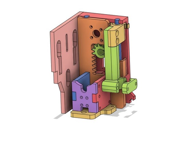
I substituted this cutting head

I printed the cutting head out of Inland petg and saw considerable flex as the head was moving in the +X direction. Tried adding stiffeners, no joy. Reprinted the components out of Prusament pla and the flex disappeared. Filament matters!
 

luvmy40

Elite member
PLA+ or ABS(if your printer is capable) would be even better. I have the same cutter assembly printed from Inland PLA. I see no flex.