Update #5.)
Finally able to start working again on the plane after graduation ceremonies this weekend; finally have a shiny new BS in electrical engineering!!
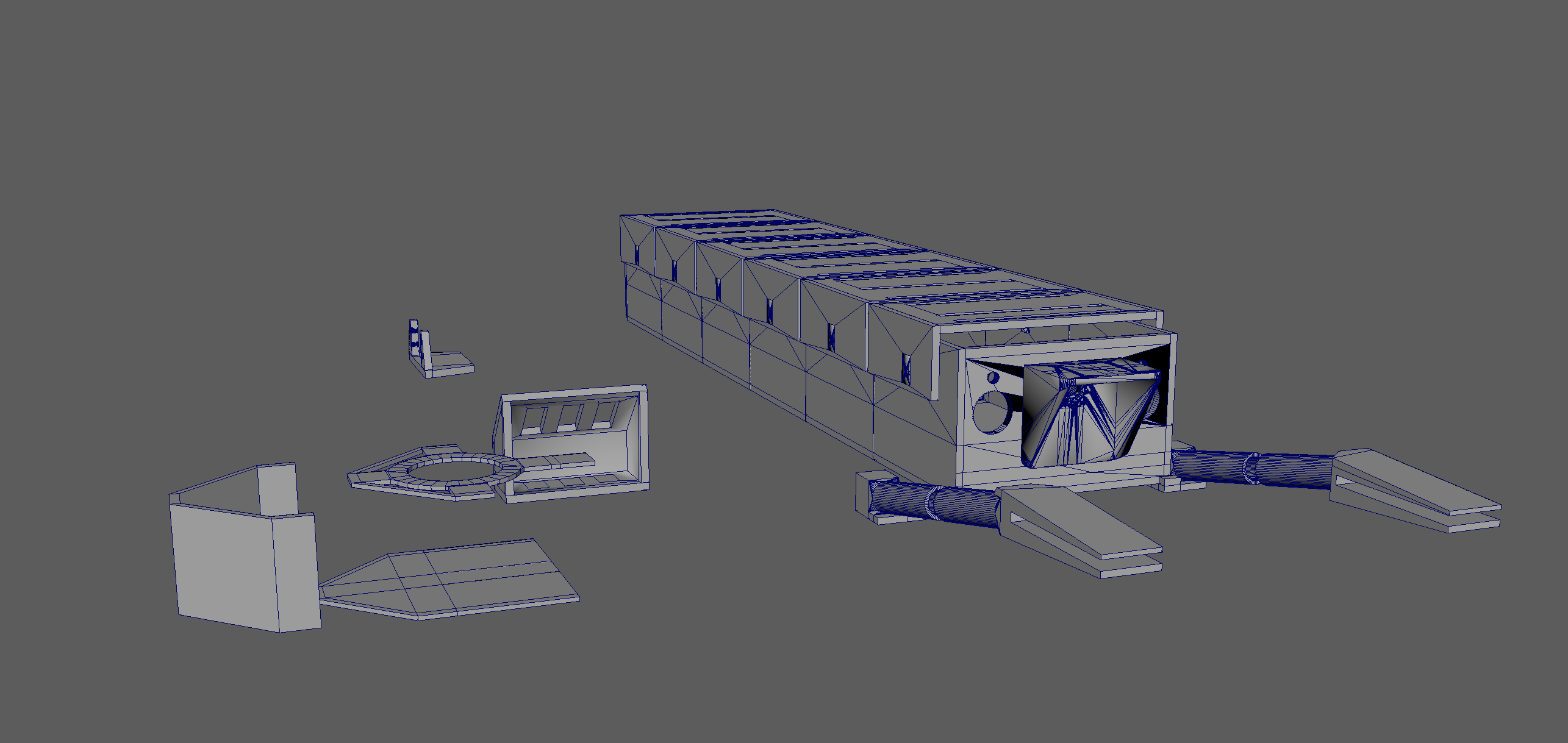
I've been busy printing the plane's body pieces (starting with the nose and motor mount). All of the pieces except for the motor mount are glued together with CA glue and Zip Kicker spray. The motor mount is fastened with M3 screws and hex nuts. This is so that I can swap out new motors and their respective mounts easily without completely dismantling the frame. Having an easily replaceable motor mount is good for maintenance since the motor mount is the most likely piece to break in the event of a crash.
Here is a pic of the motor mount, nose, and two body sections:

Notice how the plane also has a nose wheel (steerable). Also, the landing gear is tricycle styled. You can also see in the above pic a big hole in the side of the fuselage. This is for the "on/off" switch I will be installing later in the build.
Here are some close up pics of the nose landing gear, nose, and motor mount so far:


I have also been putting in a lot of work developing a 3D printed case for the Integrated Controller Board. It comes in 3 pieces:
- A bottom piece with M3 mounting holes for the PCB
- A wall piece that includes flange tabs with M3 hex nut inserts for fastening the cover piece
- A cover piece with M3 mounting holes and a center hole for wiring to run through
The bottom and wall pieces are glued together with CA glue and Zip Kicker. The cover and wall pieces are fastened using M3 screws and hex nuts.
The files for printing this box is attached.
Here are some pics:


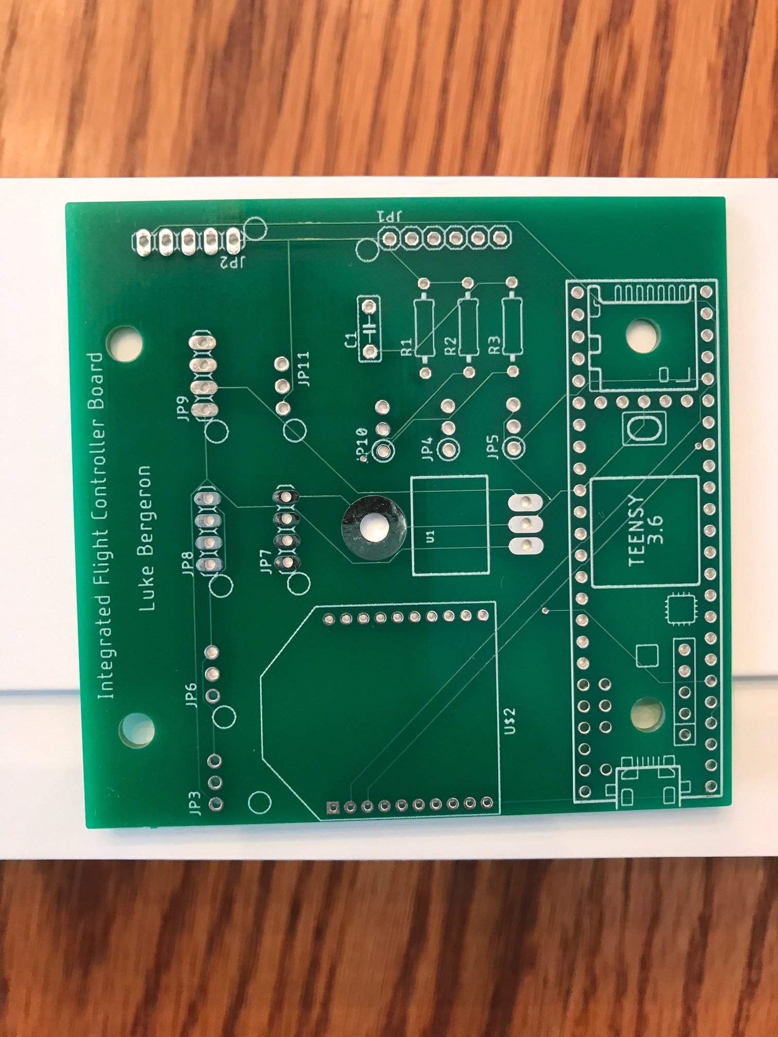
Lastly, I've been making leaps and bounds with the actual PCB and soldering everything together (but not quite finished).
The first thing to keep in mind is that printing the board layout from Eagle will help a lot when plugging things into the board (especially since I made a mistake and the DuPont connector footprints are NOT labeled on the silkscreen - oops).

It is also a good idea to have both the schematic and the board layout on a computer for more detailed reference:

Also, note that the XBee does not use normally spaced female connectors:

I also use several of these JST-XH 3S connectors on the PCB itself:

I generally prefer these to DuPont connectors since these actually "lock" in place and can only mate one way - no way to accidentally plug them in wrong.
Here are some close up pics of the smaller pieces I'm using for the PCB:
Full sized female connectors (cut to size):

Passive components (caps and resistors):

5V Linear Regulator (bent at 90 degrees):

Teensy "on/off" switch:

Male DuPont connector:

Here's how I solder the JST-XH 3S connectors:

Note how you always want to solder connectors while mated. This is especially important when the connectors are plastic - if the solder heat deforms one of the pieces, you want to deform the other one in a like fashion so that they still mate even when slightly deformed.
Here's how I soldered the XBee:

Here is the finished board (minus the DuPont male connectors):

Lastly, I've been testing the PCB one piece at a time. This board has a decent amount of stuff going on, so trying to test everything at once is not only dangerous, but overwhelming - especially when trying to debug.
First, I tested the Teensy by itself on a breadboard and NOT on the PCB. I uploaded a sketch to the Teensy that flashed the LED on pin 13. It worked!
Next, I tested the same Teensy sketch, but on the PCB with power from the BEC. It worked!

Next, I tested the ability for the XBee to communicate not only with another XBee, but also with the Teensy. It worked!

For this XBee test, I used a second XBee that was connected to my laptop via an "explorer dongle" and controlled through Digi's software: XCTU. As I sent data (ASCII characters) to the Teensy via the XBee network, the Teensy was able to report the same data correctly in the Arduino serial monitor.
The code for both these tests are attached.
I plan on testing the rest of the PCB functionality over the next week.


