Power_Broker

Active member
Welcome to my build log for my next Arduino controlled RC scratch built airplane!

Much of this project is going to be based off of work (especially in terms of software) found in my previous build log here. After my *very* successful test flight with my last Arduino plane, I've decided to change airframes and do an extensive electronics hardware update. Hence the new build log.

Also, if you are not familiar with what Arduinos are, check out this website. It explains all the basics on what they are and a little on how to use one (they are basically really small computers). I'm using a couple of Arduinos to make a custom hand controller and custom flight controller in an attempt to make a fully functional RC airplane.

My new plane will be called "Screamin' Seagull II".


Plan for this build:
1.) Design, fabricate, and implement a new Arduino based controller board that is flexible enough to be used for the hand controller and flight controller. This means that I can order one set of PCBs of the same design instead of having to make two separate designs (one for the hand controller and one for the flight controller). This makes the hardware setup easier and more affordable.

2.) Further develop and use the ArdUAV flight software library for control of the plane.

3.) Implement and test various autopilot features in a simulated environment (Processor-In-Loop Simulation) using an Arduino with the popular computer game War Thunder. This will allow me to test, debug, and develop autopilot logic before implementing it on my plane. I'd rather catch the bugs in a simulation before it crashes my real RC plane.

4.) Migrate validated autopilot features from my War Thunder/Arduino Processor-In-Loop Simulation (PIL Sim) to the ArdUAV library for use on my plane.

5.) Conduct live tests of the autopilot features and further mature the plane's performance.

Long-Term Goals:
1.) Achieve autonomous straight and level flight

2.) Achieve autonomous coordinated turns

3.) Achieve autonomous GPS waypoint flying

4.) Achieve autonomous takeoffs

5.) Achieve autonomous landings


Please...if you have any questions or suggestions, I would love to hear them!
 

Power_Broker

Active member
Update #1.)

I completed a new PCB design and ordered a set of 10 boards from SeeedStudio.com. The boards should arrive sometime during the week after next.

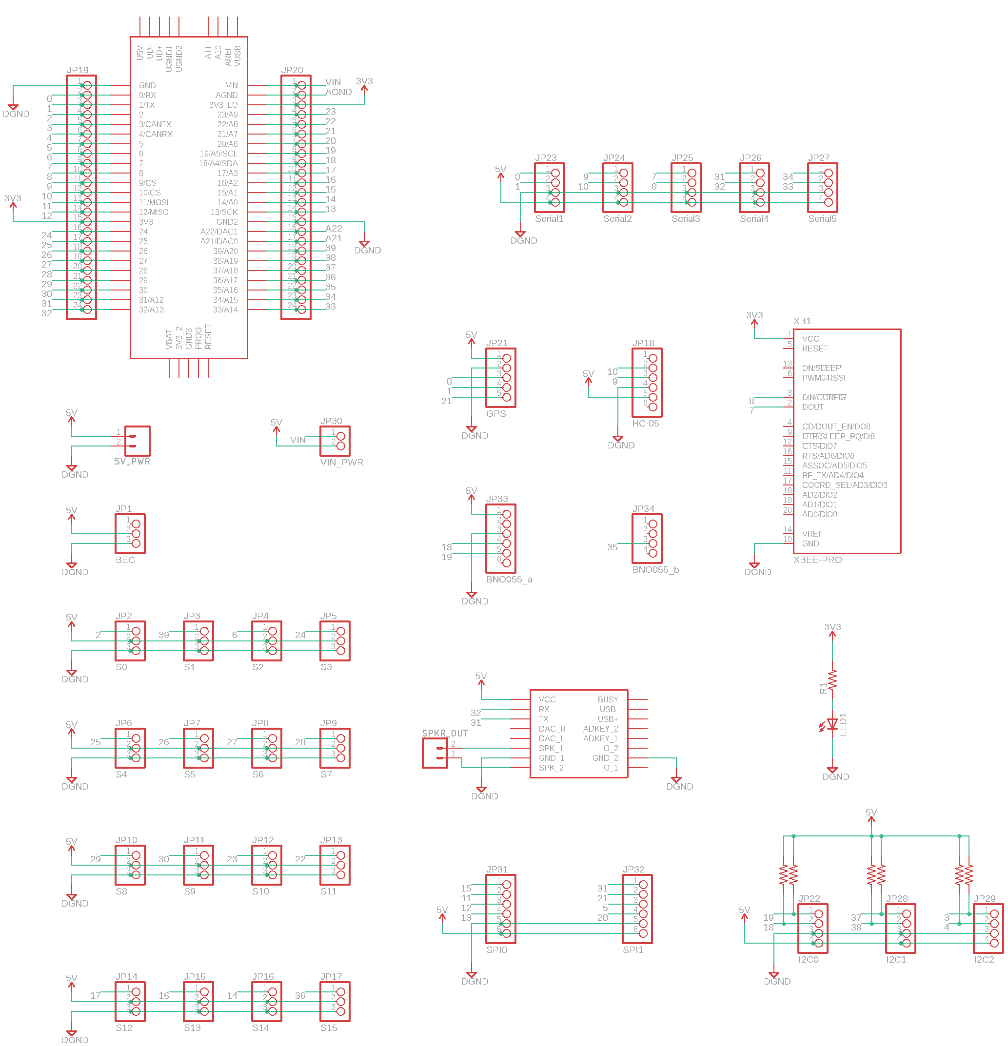
The new PCB design accepts a Teensy 3.5 microcontroller (the "Arduino) and breaks out its pins to different headers/devices. As it stands the PCB allows the Teensy to interface with 5 UART serial ports, 3 I2C ports, 2 SPI ports, 1 GPS, 1 Bluetooth, 1 XBee, 1 BNO055 IMU, 1 MP3 player, and 16 servos.

I will also design and make a 3D printed enclosure for the PCB.

Here are some pics of the PCB schematic and board layout and the Gerber files are also attached (if you want to order your own):

multipurposeboard_board.png


multipurposeboard_schematic.png
 

Attachments

  • multipurposeboardteensy.zip
    255.9 KB · Views: 0

clolsonus

Well-known member
Hi Power Broker, hope you don't mind if a throw several comments your way. I know there are a million good ways to do everything so if any of this helps, great. If not, no worries!

I didn't spot an IMU on your board, are you planning to integrate something externally? Bolderflight makes a series of Teensy "backpacks". One includes an MPU9250 which is close to end of life, but still a pretty nice and very commonly used IMU: https://bolderflight.com/products/teensy/
For one of my projects I integrated an mpu9250 breakout board from goodluckbuy: https://www.goodluckbuy.com/cjmcu-10dof-mpu9250bmp280-9-axis-accelerator-altitude-sensor-module.html
I like having the IMU rigidly attached to my main board.

Power: if I read the schematic right, you are just planning to take 5v in from your BEC. For some future version you might consider on board power regulation. I really like this little guy: https://www.adafruit.com/product/1065 (Higher amp versions are also available from other sources like mouser.)
Advantages of on-board power regulation: Some BEC's output voltage sags a lot under load and can vary somewhat when you run the servos. The above linked regulator will give you rock solid 5v no matter what (but you need to feed in 6.5 volts minimum.) On board power regulations lets you power your avionics directly from your main battery ... then even if you fry a motor or esc, you can still keep some flight control (don't ask me how I came to think that is useful.) :) You can add a simple voltage divider circuit and measure your main battery voltage right at the teensy. If you send that value down to the ground station via the xbee, it can be a pretty handy bit of data to have in flight.

I always struggle with what's best to put on the main board and what's best to keep external. I've worked on some projects where we've tried to pile everything on a single board (gps, radio modem, imu, rc receiver, literally everything.) That can work ok for a very specific application but isn't very flexible. I think I prefer more flexibility with mounting my radio modem, gps, and rc receiver externally. On the other hand the fewer external connectors you have and the fewer external wires ... that's fewer crimps to break or wires to fray or pull out in transport.

This may be a ways down the road, but we have a real EKF (extended kalman filter) that runs on the teensy 3.6 at pretty fast rates. If you feed in gps and fast rate IMU, the EKF will compute your roll, pitch, and heading angles right on board. This can be useful for navigation and autonomous flight control. There are simpler algorithms (like madgwick and mahoney) that take fewer resources, but the UMN 15-state EKF performs well even in turns and acceleration: https://github.com/bolderflight/RAPTRS/blob/master/software/src/soc/common/uNavINS.cpp
px4 and ardupilot also have EKF's, but I think they are pretty tightly wound up into their code bases. Ours should be pretty easy to drop in. There are a few prerequisite libraries, but at run time, you just pass in the GPS and IMU data as you get it and read the orientation and position out. Our EKF converges to "true" heading and doesn't need magnetometers (and isn't subject to magnetometer calibration errors) but it takes some motion to get converged to the correct heading (usually a few 10's of seconds of flying or moving around is all you need.)

The teensy does inverted 100,000 baud serial directly, so you can plug an frsky sbus receiver into it directly. I think you are doing pilot commands though your xbee, but if you ever wanted to support a more traditional RC system for manual flight, that's pretty easy to do. Here is my SBUS parsing code (for an example): https://github.com/AuraUAS/aura-sensors/blob/master/sbus.ino It's not that hard to write your own, but there were a couple edge cases that caught me off guard on my first try.

I can also share ublox8 parsing code if that helps: https://github.com/AuraUAS/aura-sensors/tree/master/src/UBLOX8 We have a specific way we configure the ublox8 and then we only output the NAVPVT message. I can share our setup files with you too if you like. (I think you can load them into ucenter and update your gps settings, but I have a different way I usually do it so I can avoid booting up windows.) https://github.com/AuraUAS/aura-core/blob/master/src/sensors/ublox8-config.txt

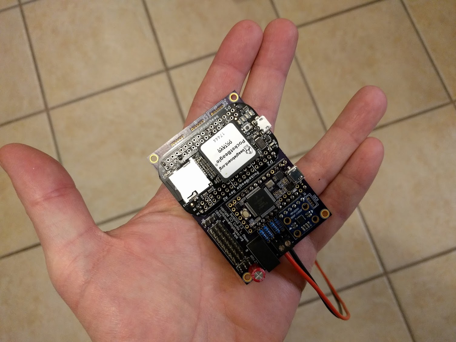
Here's the little guy I built around a teensy-3.2 and a pocketbeagle (I actually haven't flown this yet, but I have flown similar earlier versions):
board-v2.2.jpg


Ideally you won't like or use any of these options, but maybe some of them will give you ideas for how to do things better than I did. :)
 
Last edited:

Power_Broker

Active member
I didn't spot an IMU on your board, are you planning to integrate something externally?

I have a breakout for a BNO055 IMU directly on the PCB for sturdy mounting and minimal offset angles.

Power: if I read the schematic right, you are just planning to take 5v in from your BEC. For some future version you might consider on board power regulation. I really like this little guy: https://www.adafruit.com/product/1065 (Higher amp versions are also available from other sources like mouser.)
Advantages of on-board power regulation: Some BEC's output voltage sags a lot under load and can vary somewhat when you run the servos.

I'm running a standalone 10A Castle BEC for external power - there is very little chance I'll get close to demanding 10A so voltage sag shouldn't be a big issue.

You can add a simple voltage divider circuit and measure your main battery voltage right at the teensy. If you send that value down to the ground station via the xbee, it can be a pretty handy bit of data to have in flight.

That is a really good point, I'll see if I can implement that! ;)

I always struggle with what's best to put on the main board and what's best to keep external. I've worked on some projects where we've tried to pile everything on a single board (gps, radio modem, imu, rc receiver, literally everything.) That can work ok for a very specific application but isn't very flexible. I think I prefer more flexibility with mounting my radio modem, gps, and rc receiver externally. On the other hand the fewer external connectors you have and the fewer external wires ... that's fewer crimps to break or wires to fray or pull out in transport.

The really cool part about this PCB is that it gives you options as to what you want to mount on the PCB vs externally (except for the GPS - that has to be externally mounted). The flexibility comes from having hard PCB mounts (i.e. for the XBee and MP3 player) that have their signals broken out with connectors that can interface with externally mounted devices. For instance, if I am currently using the XBee mounted to the PCB and hardwired to the Serial1 port, I can take out the XBee, mount it externally, and then (without having to change the software AT ALL) I can connect the XBee to the Serial1 port breakout pins.

This may be a ways down the road, but we have a real EKF (extended kalman filter) that runs on the teensy 3.6 at pretty fast rates. If you feed in gps and fast rate IMU, the EKF will compute your roll, pitch, and heading angles right on board. This can be useful for navigation and autonomous flight control. There are simpler algorithms (like madgwick and mahoney) that take fewer resources, but the UMN 15-state EKF performs well even in turns and acceleration: https://github.com/bolderflight/RAPTRS/blob/master/software/src/soc/common/uNavINS.cpp
px4 and ardupilot also have EKF's, but I think they are pretty tightly wound up into their code bases. Ours should be pretty easy to drop in. There are a few prerequisite libraries, but at run time, you just pass in the GPS and IMU data as you get it and read the orientation and position out. Our EKF converges to "true" heading and doesn't need magnetometers (and isn't subject to magnetometer calibration errors) but it takes some motion to get converged to the correct heading (usually a few 10's of seconds of flying or moving around is all you need.)

That's pretty cool, I'll have to check it out.

I think you are doing pilot commands though your xbee

I'm actually using 3DR 915MHz 500mW radios for commands; XBee Pro S1 for telemetry.

Here is my SBUS parsing code (for an example): https://github.com/AuraUAS/aura-sensors/blob/master/sbus.ino It's not that hard to write your own, but there were a couple edge cases that caught me off guard on my first try.

If you take a look at the ArdUAV library, I have a scratch built communication standard/library called AirComms. You should take a look at it - I'm curious to know your thoughts on it. Also, what were the edge cases that caught you off guard?

I can also share ublox8 parsing code if that helps: https://github.com/AuraUAS/aura-sensors/tree/master/src/UBLOX8 We have a specific way we configure the ublox8 and then we only output the NAVPVT message. I can share our setup files with you too if you like. (I think you can load them into ucenter and update your gps settings, but I have a different way I usually do it so I can avoid booting up windows.) https://github.com/AuraUAS/aura-core/blob/master/src/sensors/ublox8-config.txt

I'm using a NEO-6M GPS unit configured to output only GPRMC sentences at 10Hz, 115200 baud. The GPS configuration and parsing code (much like the AirComms library) used was scratch designed and already included in the ArdUAV library. Your parsing code looks quite impressive, though!


Thanks for your feedback! :cool:
 

clolsonus

Well-known member
I have a breakout for a BNO055 IMU directly on the PCB for sturdy mounting and minimal offset angles.

Ahh, got it. I didn't recognize the part number.

I'm running a standalone 10A Castle BEC for external power - there is very little chance I'll get close to demanding 10A so voltage sag shouldn't be a big issue.

That should work, but you may want to measure your output under load. It will be well under the voltage you programmed the thing to put out. And pay attention to what running servos hard does to the voltage. I flew for a few years with one of these without any trouble, but I had to pump up the target voltage to several tenths of a volt higher than what I wanted so that under load, it ended up being around 5v. The nice thing about the more modern voltage regulators is that they can nail 5v exactly to within a few hundredths of a volt even as the load changes ... and you never have to worry or think about it. But anything from CC should be solid.

The really cool part about this PCB is that it gives you options as to what you want to mount on the PCB vs externally (except for the GPS - that has to be externally mounted). The flexibility comes from having hard PCB mounts (i.e. for the XBee and MP3 player) that have their signals broken out with connectors that can interface with externally mounted devices. For instance, if I am currently using the XBee mounted to the PCB and hardwired to the Serial1 port, I can take out the XBee, mount it externally, and then (without having to change the software AT ALL) I can connect the XBee to the Serial1 port breakout pins.

It's always a trick to juggle enough flexibility without too much flexibility ...

I'm actually using 3DR 915MHz 500mW radios for commands; XBee Pro S1 for telemetry.

On my systems I've always used stock RC gear for manual control and the 3DR modems for telemetry down and commands up.

If you take a look at the ArdUAV library, I have a scratch built communication standard/library called AirComms. You should take a look at it - I'm curious to know your thoughts on it. Also, what were the edge cases that caught you off guard?

For my first attempt at sbus parsing I found my parser could get out of sync if there was any byte corruption on the uart line (and there always will be at some point somewhere it seems like.) Wasn't a big deal once I figured out what was happening.

I don't have any specific comments on your aircomms code. If it works well and serves your purposes it should do great. I like that you've added a checksum ... the real world will figure out every possible way to subtly or not-so-subtly corrupt your messages. Error handling is imporantant ... even if the low level protocol checks and corrects, you can still fill up the input bucket and drop bytes that way if you transfer too much too fast.

I could say a few things about the protocol I've implemented if you want, but this should be more about your project. There is also Mavlink. My system is a lot like mavlink, I have several different packet (message) types that are sent down from the airplane. As you go forward you may find more and more things that are useful to send to the ground station. I have found it's useful to define several packet types. But I wouldn't stress too much about it ... I like to say: "It's only software". You can add, change, delete, refactor any time you decide it's time to jump up a level of complexity.

I'm using a NEO-6M GPS unit configured to output only GPRMC sentences at 10Hz, 115200 baud. The GPS configuration and parsing code (much like the AirComms library) used was scratch designed and already included in the ArdUAV library. Your parsing code looks quite impressive, though!

The ublox6 is solid. We had some weird problems with the ublox7 (in fact it crashed one of our planes.) The ublox8 was back to being solid. I like the NAVPVT message the ublox8 added which gives position and velocity and everything else we need in a single message.

I like your overall approach ... you are keeping things moving forward which is super important. It's easy to get distracted with trying to build the mother of all systems and then after a while you realize you've designed something that can't be built in a human lifespan. A lot of projects get as far as a cool web site, and then run aground. Great that you've got some test flights in all ready. Getting to the point where you have something working is the hardest part for any project. From here on out it's just a matter of tweaks here and there, additions once in a while, improve this, improve that (which goes on forever.) But you are flying already which is awesome.
 
Last edited:

Power_Broker

Active member
Update #2.)

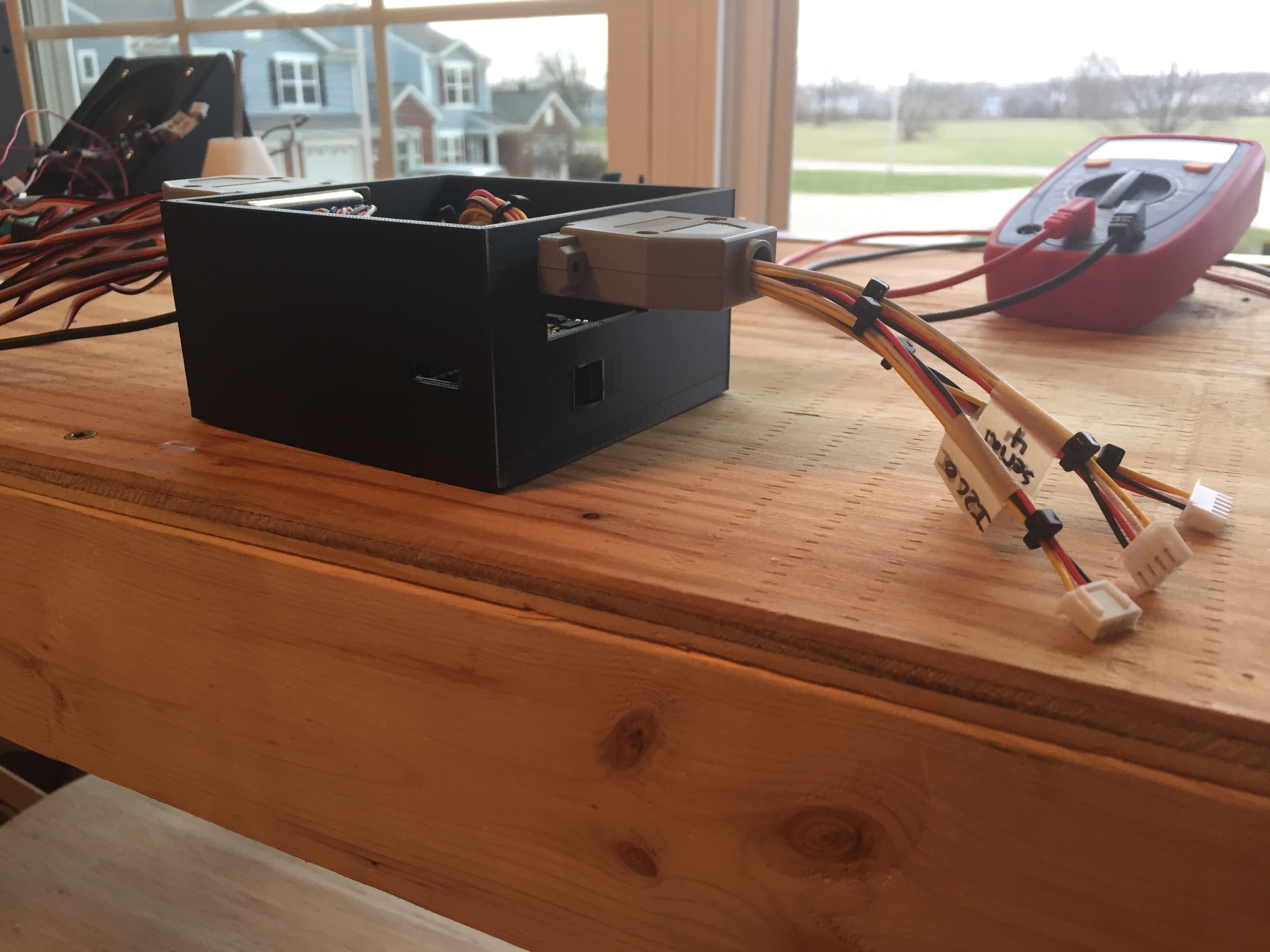
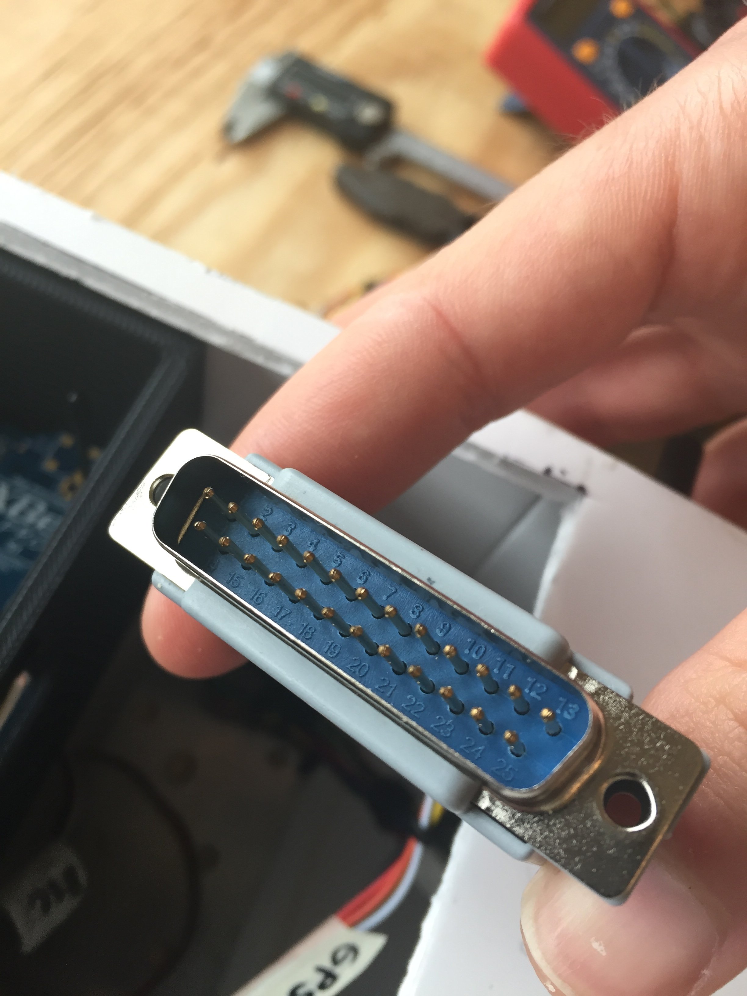
While waiting for the PCBs to arrive (currently in production), I've decided to work on some wiring for the new plane. Mainly I've been doing a pinouts and soldering D-Sub 25 connectors that will be used to interface with the new electronics box/PCBs. The on board electronics box will have 3 D-Sub 25 connectors and will have the following pinout:

Pin mapping picture for reference:

25Pin.png


DB25_1:
DB Pin: - PCB Pin: - Outside Pin:
-----------------------------------------------------
1 - BEC GND - BEC GND
2 - Servo 1 GND - Right Aileron Servo GND
3 - Servo 1 +5V - Right Aileron Servo +5V
4 - Servo 1 Signal - Right Aileron Servo Signal
5 - Servo 2 GND - Left Aileron Servo GND
6 - Servo 2 +5V - Left Aileron Servo +5V
7 - Servo 2 Signal - Left Aileron Servo Signal
8 - Servo 3 GND - Pitot Tube GND
9 - Servo 3 +5V - Pitot Tube +5V
10 - Servo 3 Signal - Pitot Tube Signal
11 - Servo 0 GND - Nosewheel Servo GND
12 - Servo 0 +5V - Nosewheel Servo +5V
13 - Servo 0 Signal - Nosewheel Servo Signal
14 - BEC +5V - BEC +5V
15 - Servo 4 GND - Rudder Servo GND
16 - Servo 4 +5V - Rudder Servo +5V
17 - Servo 4 Signal - Rudder Servo Signal
18 - Servo 5 GND - FPV Pan Servo GND
19 - Servo 5 +5V - FPV Pan Servo +5V
20 - Servo 5 Signal - FPV Pan Servo Signal
21 - Servo 6 GND - FPV Tilt Servo GND
22 - Servo 6 +5V - FPV Tilt Servo +5V
23 - Servo 6 Signal - FPV Tilt Servo Signal
24 - GND - Camera GND
25 - +5V - Camera +5V

DB25_2:
DB Pin: - PCB Pin: - - Outside Pin:
-----------------------------------------------------
1 - Servo 7 GND - Bomb Bay Servo GND
2 - Servo 7 +5V - Bomb Bay Servo +5V
3 - Servo 7 Signal - Bomb Bay Servo Signal
4 - Servo 8 GND - NC
5 - Servo 8 +5V - NC
6 - Servo 8 Signal - NC
7 - Servo 9 GND - NC
8 - Servo 9 +5V - NC
9 - Servo 9 Signal - NC
10 - Servo 10 GND - NC
11 - Servo 10 +5V - NC
12 - Servo 10 Signal - NC
13 - Servo 11 GND - NC
14 - Servo 11 +5V - NC
15 - Servo 11 Signal - NC
16 - Servo 12 GND - NC
17 - Servo 12 +5V - NC
18 - Servo 12 Signal - NC
19 - Servo 13 GND - NC
20 - Servo 13 +5V - NC
21 - Servo 13 Signal - NC
22 - Servo 14 GND - Elevator Servo +5V
23 - Servo 14 +5V - Elevator Servo GND
24 - Servo 14 Signal - Elevator Servo Signal
25 - NC - NC

DB25_3:
DB Pin: - PCB Pin: - Outside Pin:
-----------------------------------------------------
1 - Serial5 +5V - 3DR/XBee +5V
2 - Serial5 GND - 3DR/XBee GND
3 - Serial5 TX - XBee RXD
4 - Serial5 RX - 3DR TXD
5 - GPS +5V - NEO-6M +5V
6 - GPS GND - NEO-6M GND
7 - GPS TXD - NEO-6M TXD
8 - GPS RXD - NEO-6M RXD
9 - GPS PPS - NEO-6M PPS
10 - I2C0 +5V - LiDAR +5V
11 - I2C0 GND - LiDAR GND
12 - I2C0 SDA - LiDAR SDA
13 - I2C0 SCL - LiDAR SCL
14 - NC - NC
15 - NC - NC
16 - NC - NC
17 - NC - NC
18 - NC - NC
19 - NC - NC
20 - NC - NC
21 - NC - NC
22 - NC - NC
23 - NC - NC
24 - NC - NC
25 - NC - NC


Here are some pictures of me working on soldering some of the connections:
IMG_4697.JPG IMG_4698.jpg
 

Power_Broker

Active member
Update #3.)

Got the PCBs, tested them, and they work perfectly!!

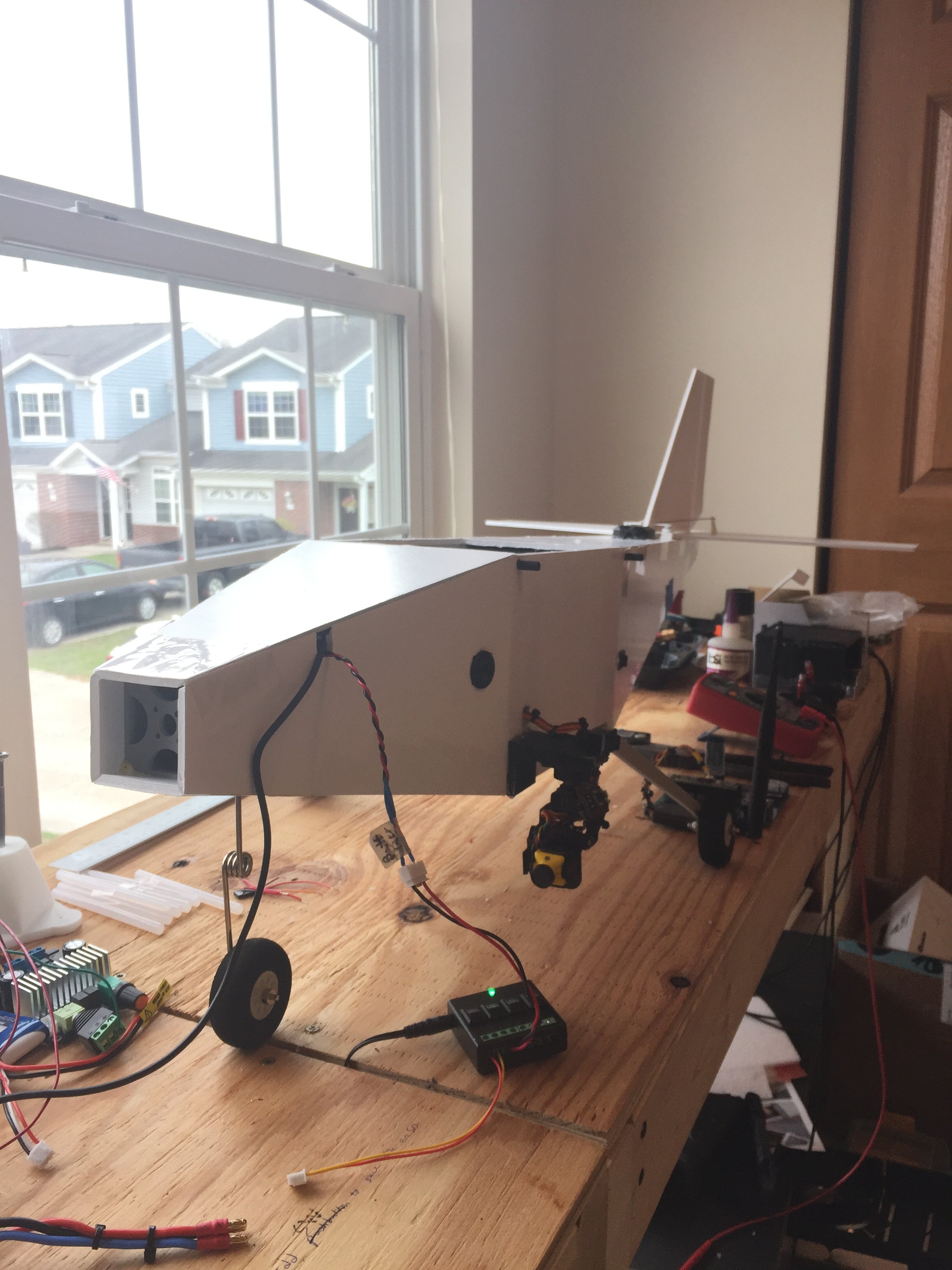
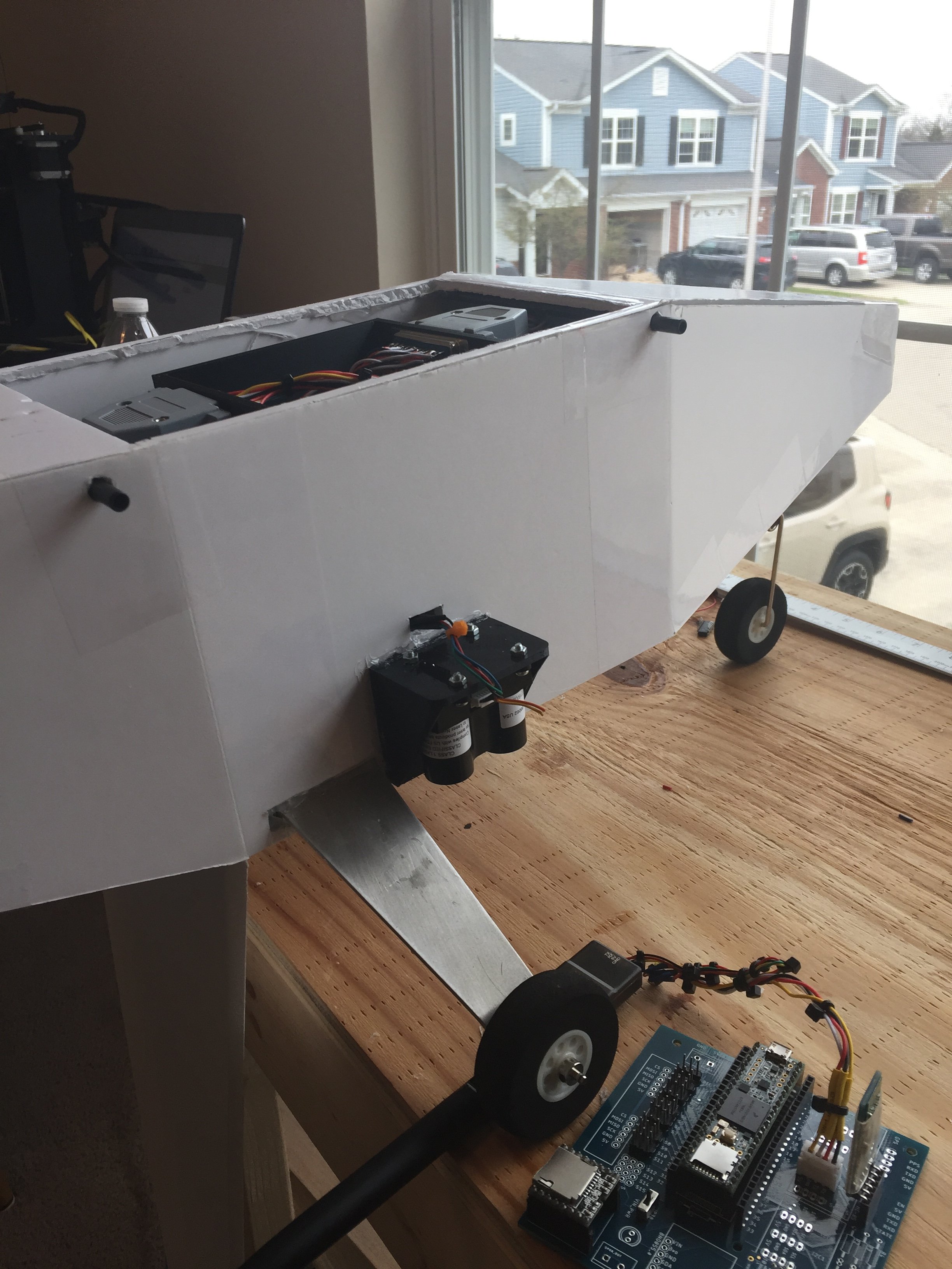
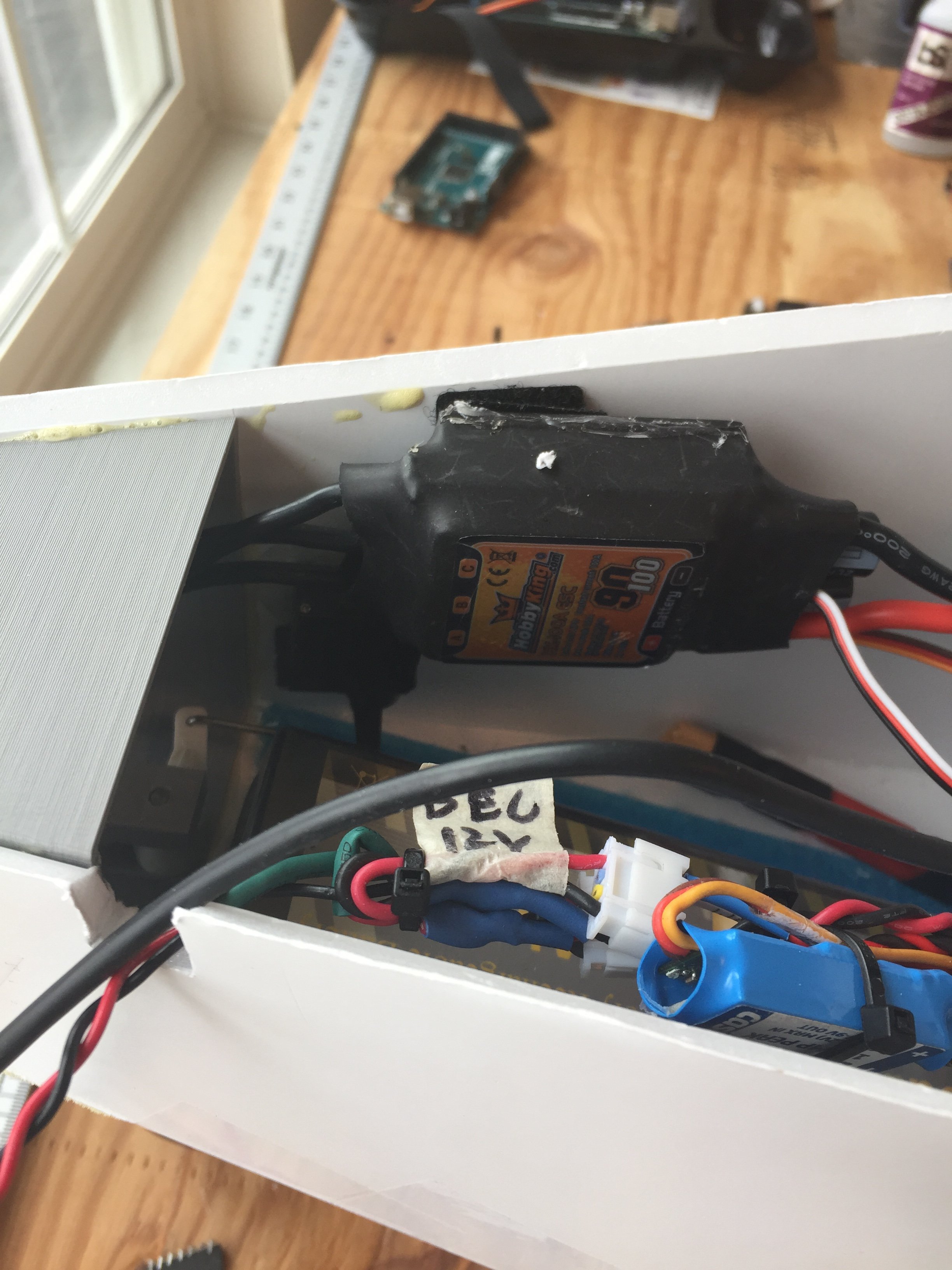
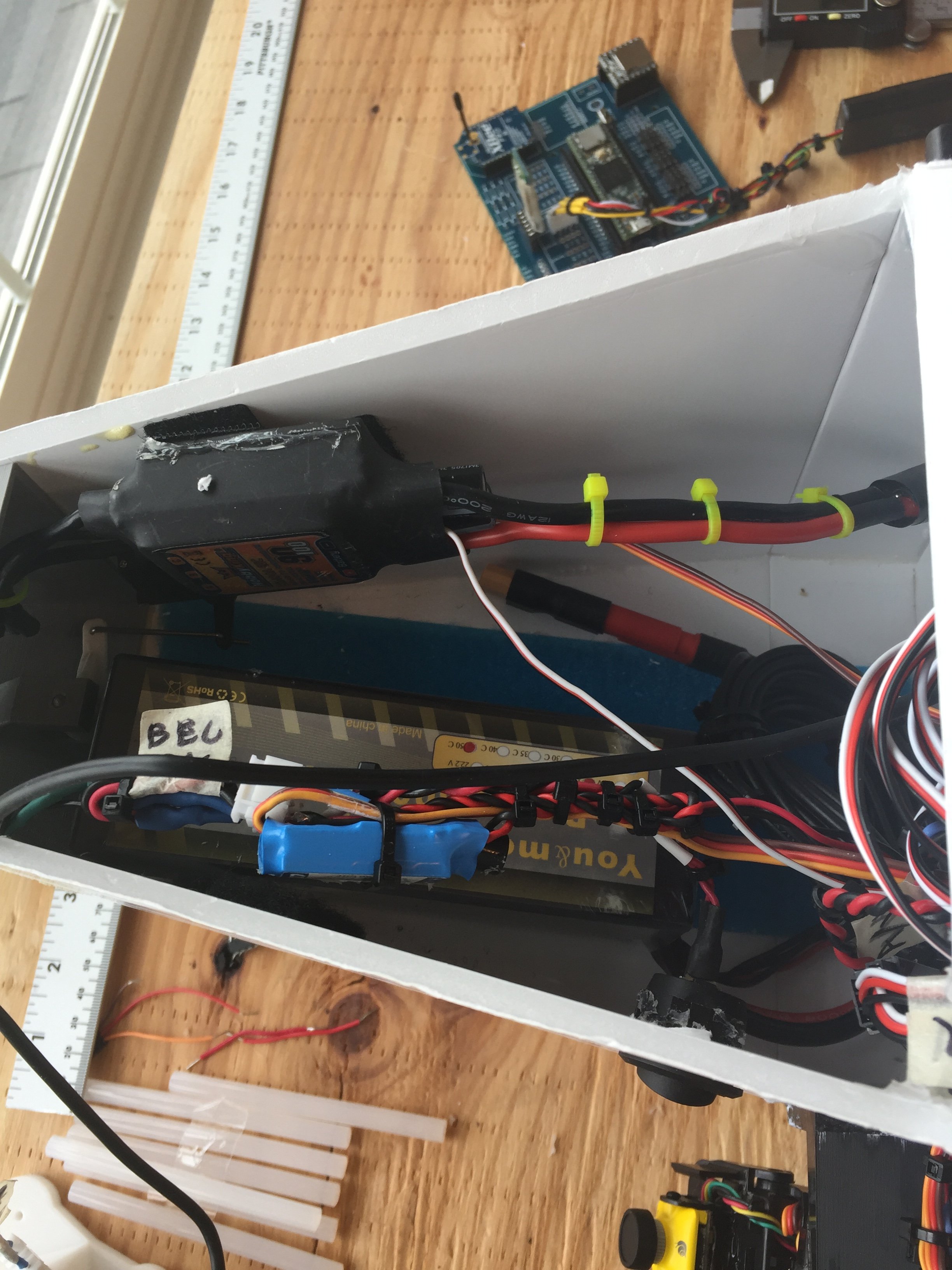
Since my last post I've been doing a ton of work soldering up two of the new PCBs - one for the flight controller and one for the hand controller. I've also been busy mounting all the electronics over to a custom made airframe. This airframe is unique in that it is large, has steerable landing gear, and has a bomb bay made for dropping soda cans!


Here are all the juicy pics:


Plane body:
IMG_4753.JPG

IMG_4754.JPG

IMG_4759.JPG

IMG_4760.JPG


Flight controller PCB all soldered up:

MDNE8981.JPG


Flight controller PCB in the 3D printed avionics box (.obj file attached):

IMG_4743.JPG

IMG_4745.JPG

IMG_4744.JPG

IMG_4742.JPG

IMG_E4746.JPG


Avionics box mounted inside the plane:

IMG_4761.JPG

IMG_4762.JPG

IMG_4763.JPG

IMG_4764.JPG


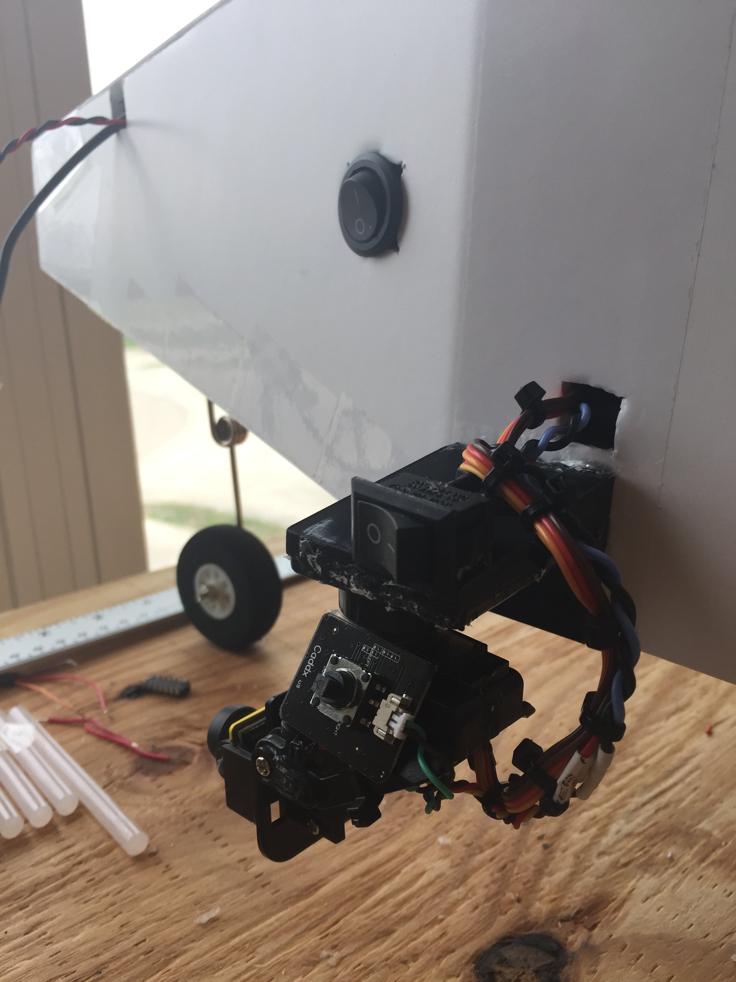
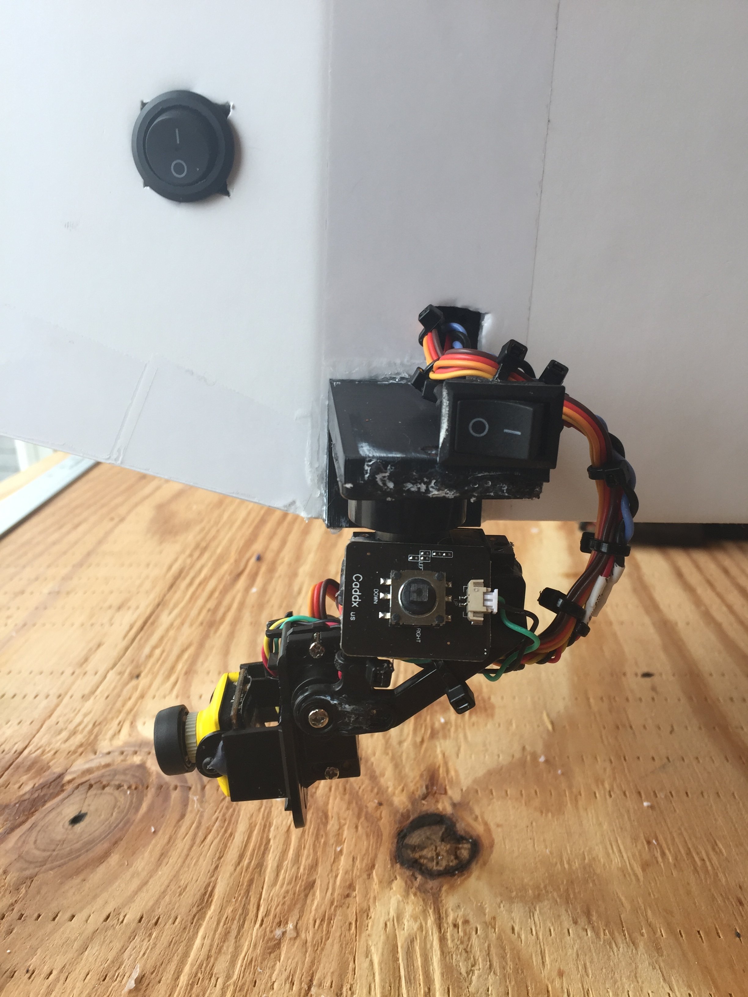
FPV camera gimbal and 3D printed mount (.obj file attached):

IMG_4757.JPG

IMG_4756.JPG

IMG_4755.JPG


Lidar Lite V3 and mount (.obj file attached):

IMG_4768.JPG


GPS and 3D printed mount (.obj file attached):

IMG_4748.JPG


Nose of the plane:

Note the USB cable and 12V battery/shore power cables. These are out only for bench testing and would be stowed for flying.

IMG_4769.JPG

IMG_4770.JPG

IMG_4771.JPG

IMG_4772.JPG


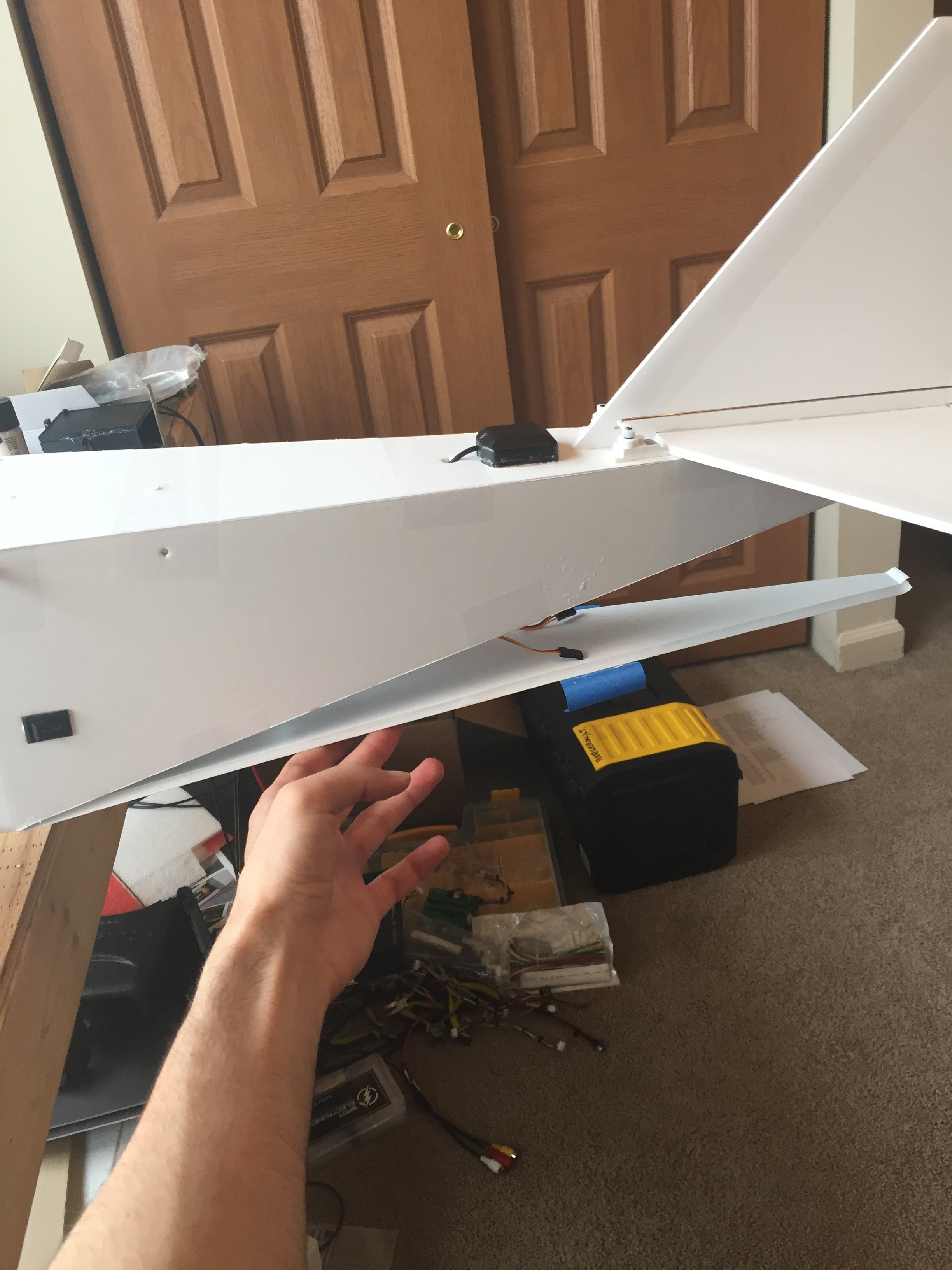
Rear of the plane:

Note how the bottom panel in the back can be "un-taped" and dropped for easy maintenance of rear mounted electronics.

IMG_4765.JPG


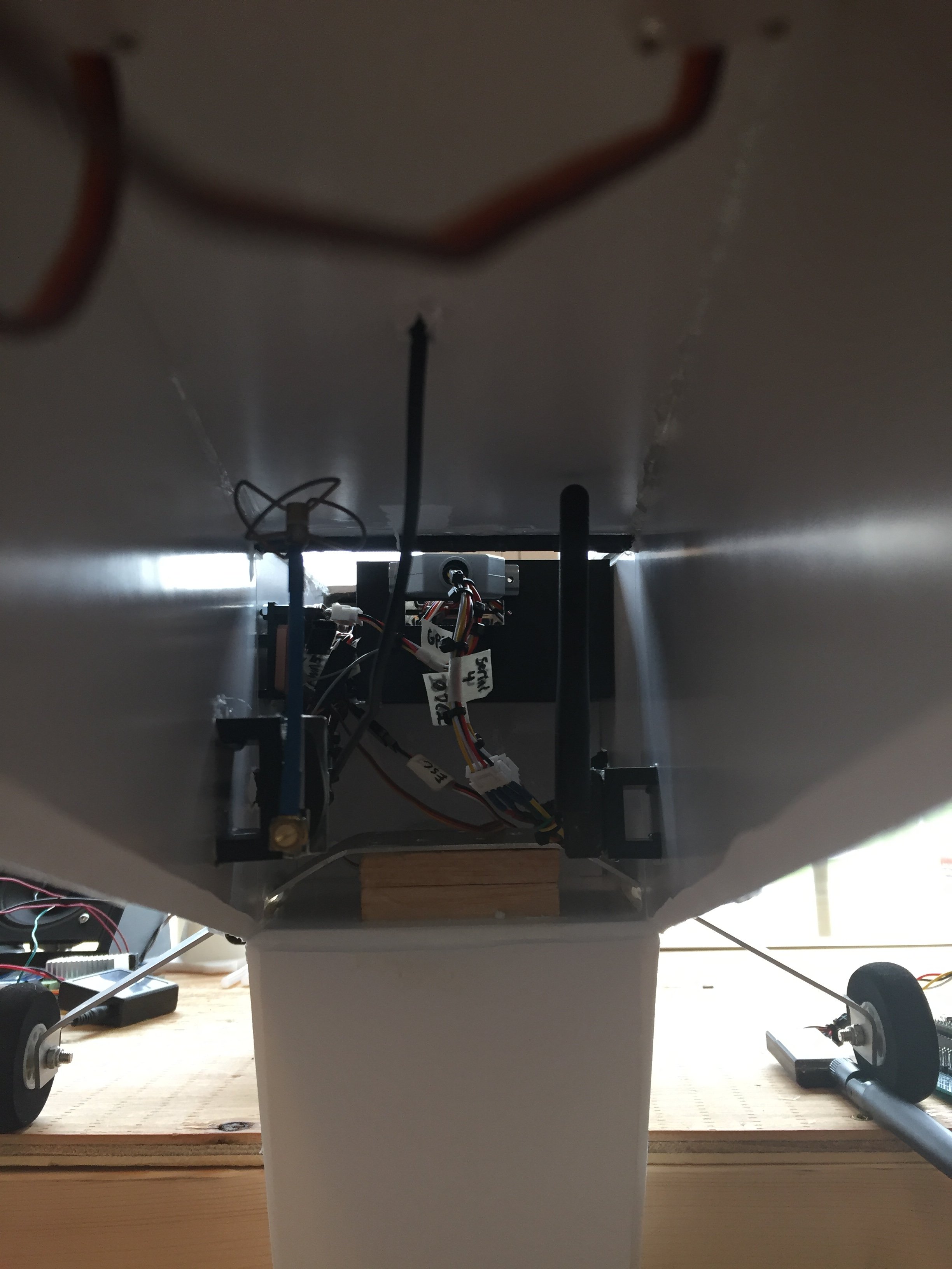
Note the FPV transmitter and 3DR radio receiver are mounted inside the tail. The 3D printed mount .obj files are attached:

IMG_4766.JPG

IMG_4767.JPG
 

Attachments

  • obj_files.zip
    159.8 KB · Views: 0

makattack

Winter is coming
Moderator
Mentor
Nice project progress! Have you not run into too many problems with having the 5.8GHz VTX, 3DR UHF transceiver so close together? I find that having two powerful transmitters so close drastically reduces my range on my builds.
 

Power_Broker

Active member
Nice project progress! Have you not run into too many problems with having the 5.8GHz VTX, 3DR UHF transceiver so close together? I find that having two powerful transmitters so close drastically reduces my range on my builds.

Thank you!

In my previous plane build, I had the FPV transmitter and 3DR receiver really close together and didn't have any range issues. I think the main reason why it's working for me is because there is a 4.885 GHz frequency difference between the "center frequencies" of the two radio modules (915MHz vs 5.8GHz) AND because one is strictly sending and the other is strictly receiving.
 

makattack

Winter is coming
Moderator
Mentor
Thank you!

In my previous plane build, I had the FPV transmitter and 3DR receiver really close together and didn't have any range issues. I think the main reason why it's working for me is because there is a 4.885 GHz frequency difference between the "center frequencies" of the two radio modules (915MHz vs 5.8GHz) AND because one is strictly sending and the other is strictly receiving.

Ah, I see. You're using the 3DR radio to recieve and not so much for transmitting. Yes, that probably makes their proximity not so much of an issue, but in my case I also find they are noisy devices that affect electronics in ways you wouldn't expect... such as jitter on servos.
 

Power_Broker

Active member
Update #4.)

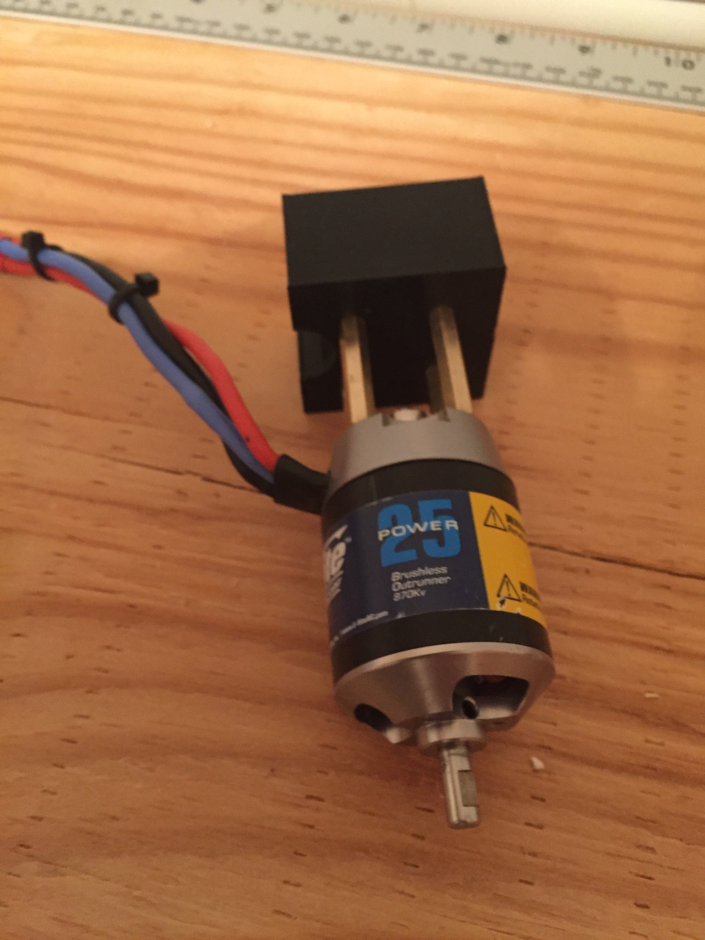
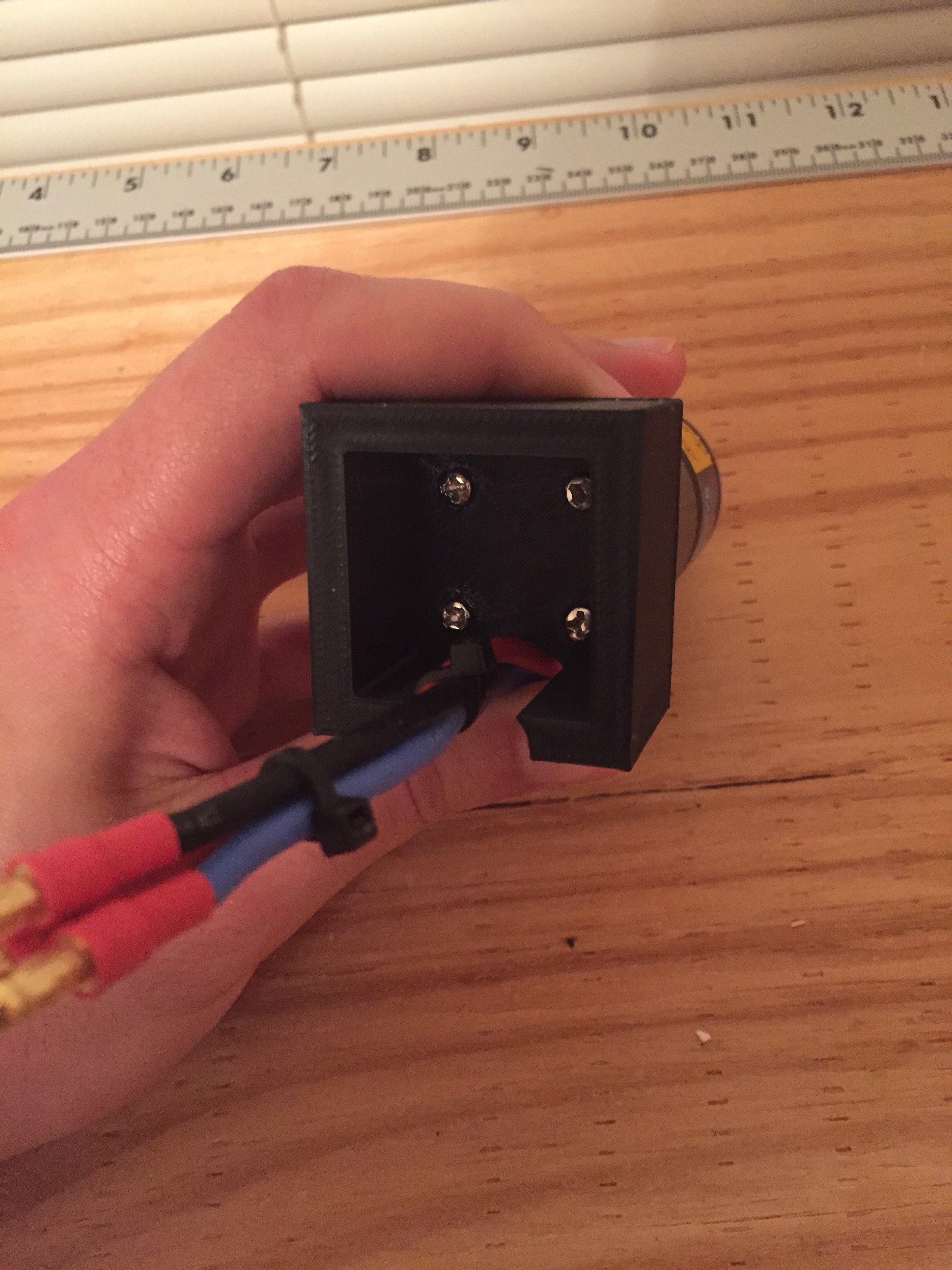
Finished designing and implementing the motor mount (.obj file attached):

IMG_4784.JPG

IMG_4785.JPG

IMG_4786.JPG
IMG_4787.JPG

IMG_4788.JPG

IMG_4789.JPG


I also finished the wiring for the hand controller. The biggest thing I had to do was cut the wires to the joysticks and solder on dupont servo connectors to them so I could plug the joysticks into my Arduino PCB. Also note that I have bluetooth implemented on the hand controller. This will allow the hand controller to communicate with the testing laptop (i.e. datalogging telemetry) wirelessly.

Here are some pics of the original joystick connectors (note the pin labeling on the one side of the connector:
IMG_4773.JPG

IMG_4774.JPG


This is one of my joysticks after soldering on the dupont servo connectors:
IMG_4775.JPG


I realized during testing that I needed to supply 3.3V to the joysticks so that I didn't damage the Arduino. If i powered the joysticks at 5V and set the joystick position within a certain range, the output voltage of the joystick will go above 3.3V and damage the Arduino. To work around this problem, I cut the red wires on the dupont servo connectors, soldered them all to a single red wire, and connected it to the 3V3 pin on the PCB. With the joysticks powered properly, there is no chance the user can damage the arduino via the joysticks.

IMG_4783.JPG

IMG_4782.JPG

IMG_4781.JPG
 

Attachments

  • motorMountObj.zip
    19.5 KB · Views: 0

Power_Broker

Active member
Update #5.)

I finished writing a Python based Graphical User Interface (GUI) to help me configure/reconfigure the many parameters set in the ArdUAV library. It's really simple, just edit the constants to be what you want, press "Apply" to save the new changes to your copy of the ArdUAV library, and reupload your code to the Arduinos for both the Ground Station and Flight Controller.

The one caveat is that you need to download and install Python and add your path to python.exe to your system path. Python can be installed here and info on setting your system path is here.

The code for the GUI can be found in the folder ArdUAV_GUI within the ArdUAV GitHub repository. Once you download it and find it, double click the .bat file and it should launch.


Here is a picture of the GUI running:

Capture.PNG
 

Power_Broker

Active member
For those of you who don't have Python installed on your machine, I decided to compile the python script into an executable using pyinstaller. I uploaded the .exe (and dependencies) to the ArdUAV repository for immediate usage.
 

Power_Broker

Active member
Update #6.)

I'm currently working on a Python GUI to run on my laptop during test flights to:
  • Display FPV video feed (real-time)
  • Control on board sensor/actuators (i.e. FPV camera gimbal angle, bomb bay door servo position, etc)
  • Display and log telemetry data from the plane
If anyone is interested in the Python source code, I have it posted in a new repo here. That being said, it is still a work in progress.

BTW, I'm planning on a test flight sometime in the next couple of weeks!
 

Power_Broker

Active member
Update #7.)

Haven't done a lot of work for this project lately (I hope people are still interested in it).

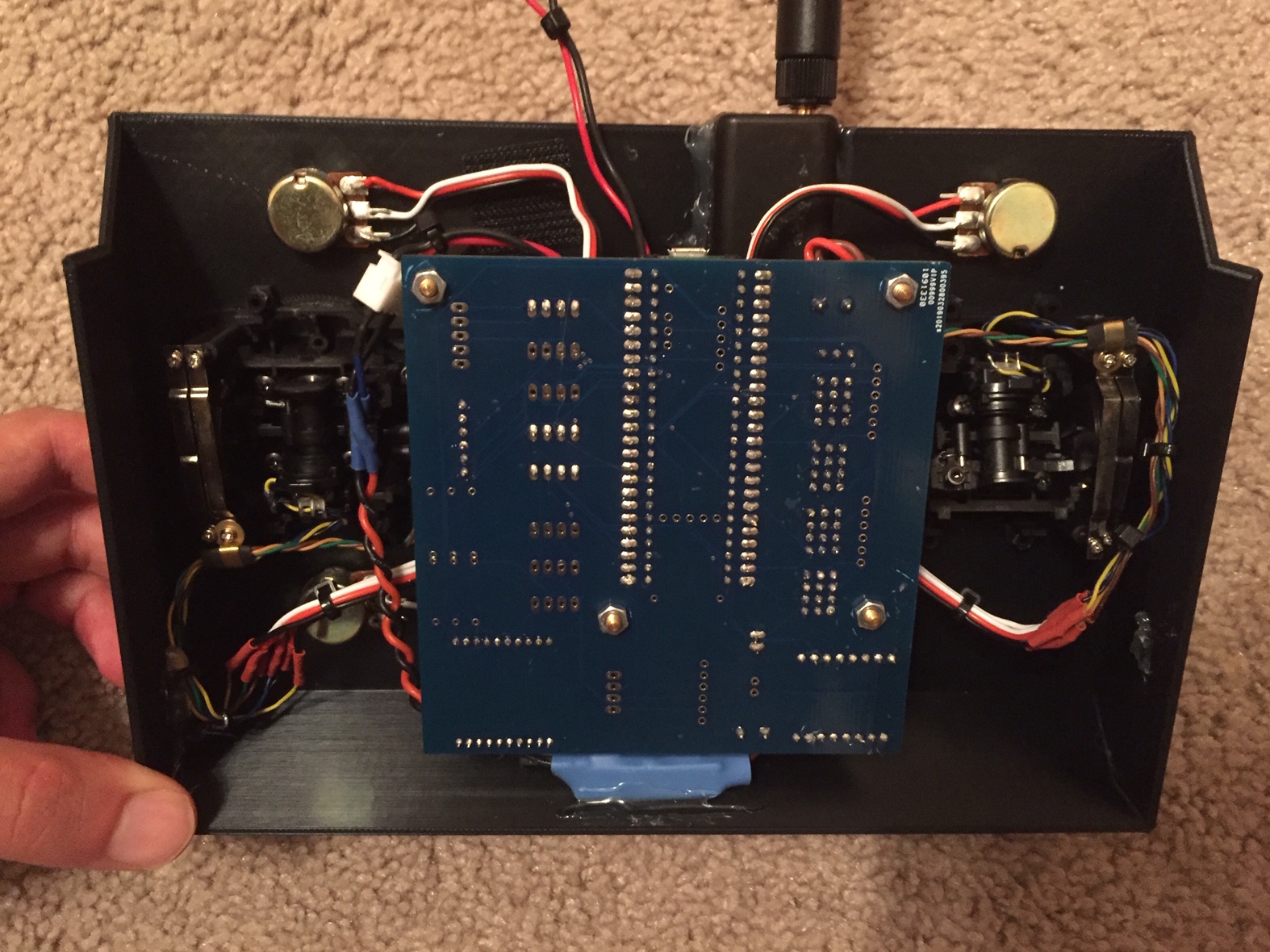
I have, though, redesigned and completed a new hand controller. I'll post the .obj file later, but for now enjoy the pics. Note that the 3 potentiometers are the pitch, roll, and yaw trim control knobs:


IMG_4906.JPG


IMG_4907.JPG


IMG_4908.jpg


IMG_4909.jpg


IMG_4910.JPG