Solved my journey to 3D print a JAS 39 gripen

telnar1236

Elite member
In terms of control surfaces, I'm going to have canards and elevons.

For the elevons, I just used a simple setup I found online

View attachment 248100

which gave me about 32° of deflection down and 50° degrees up. I'm happy with the deflection down, but I think the max deflection upwards should be at most about 20°.
View attachment 248098 View attachment 248099
The canard movement is pretty similar but a bit more advanced. This setup gives me way more deflection than I want, but I’m hoping to tune it within the transmitter. I'll probably end up using a DX6e radio transmitter, and from what I’ve found online, it should allow for some advanced tuning.
View attachment 248101
I don’t really know how to plan out moving parts, and I’m sure there’s some fine-tuning to be done, but for now, I’m pretty happy with how it looks. I’m currently printing out a prototype of the canard area just to test it in person, so we’ll see how that goes.
Looking good! Definitely agree on 50 degrees being too much deflection. Like you're thinking 20-30 degrees deflection is about right depending on the CG location.
 

NeonGreen

Member
Finally got my hands on some LW-PLA, so I’ve created a print profile based on resources I found online.

After adding all the files into the slicer, it now estimates a total weight of about 930g, which is significantly more than last time. I’m wondering if I missed some parts or if something else is going on—I’ll need to look into it and possibly find ways to reduce weight.

With 930g for the print, plus 135g for the motor, 70g for the ESC, and 250g for the battery, the total weight comes to just under 1400g.
Screenshot_26.png
I’m really happy with how the model looks! Now, I just need to do some fine-tuning. A few things I want to complete before starting the print:

  • Design a casing for the EDF to hold it securely in place.
  • Add "cheater holes" for better airflow to the EDF.
  • Create a hatch to make installation and removal of the EDF easier.
  • Design a lid that screws into place to secure the wing servos.
  • Print test pieces to fine-tune tolerances and ensure my printer settings are optimal.
  • Integrate the elevator arm into the model instead of just gluing it on, as currently planned.
  • i do also have some consern with the print quality since with the wing thata i printed it had some indents/punctuations coming right of the printer. and when printing the elevon the quality decressed notibly as it got taller so might have to tweak the speed settings.
 
Last edited:

NeonGreen

Member
Looking good! Definitely agree on 50 degrees being too much deflection. Like you're thinking 20-30 degrees deflection is about right depending on the CG location.
this is how the cg looks at the moment assuming i used 100% infill. the red is about where the edf will go and the yellow is the battery. Green is where i guess the lift will be based of absolutely nothing.
Screenshot_27.png
 

NeonGreen

Member
I beilive i haven't made a report about how the plane wing on car experiment went. it looked quite silly as one can expect.
Snapchat-1648292703.jpg


i got about 350g of lift at maybe 5° AOA decide going 70-80km/h no deflection with the elevon IMG_20250204_112551933.jpg

considering the low AOA 0 deflection of the elevon and the fimsy wall i made of sheetmetal i am going to pretend that im confident in my succes after these results.
IMG_20250203_162658624.jpg
eventualy it all came crashing down though and nothing broke luckily. the wing held up pretty well id say so thats good news atleast.
IMG_20250204_112518816.jpg IMG_20250204_112529038.jpg IMG_20250204_112534948.jpg IMG_20250202_123959983.jpg
 

L Edge

Master member
Just came across this and think your's look silly. I used a truck hood with my actual model when I was experimenting with swept back and forward swept wings for morphing a wing in flight.

For canards, I did something different for mounting. I have a Viggen, and also have done a lot on exploring canards on fighters, so I mounted 2 into the fuse(one on each side) and also allowed me to explore the canards as ailerons.

IMG_1482.JPG


I just glued servo to fuse, installed a large servo arm flush with foam canard section (allowed servo screw to tighten to spline) and set tx radio program to extra elevators (subtrim sets ) zero degrees and set max angle by reducing extreme travel.

Since the FT Vegan has a large delta wing, set canards to elevons( canards now have 2 extra ailerons giving it a better roll rate as well as improving pitch). Used mode 1 no canards, mode 2 with elevator, mode 3 with second set of elevons.
 

NeonGreen

Member
Just came across this and think your's look silly. I used a truck hood with my actual model when I was experimenting with swept back and forward swept wings for morphing a wing in flight.

For canards, I did something different for mounting. I have a Viggen, and also have done a lot on exploring canards on fighters, so I mounted 2 into the fuse(one on each side) and also allowed me to explore the canards as ailerons.

View attachment 248137


I just glued servo to fuse, installed a large servo arm flush with foam canard section (allowed servo screw to tighten to spline) and set tx radio program to extra elevators (subtrim sets ) zero degrees and set max angle by reducing extreme travel.

Since the FT Vegan has a large delta wing, set canards to elevons( canards now have 2 extra ailerons giving it a better roll rate as well as improving pitch). Used mode 1 no canards, mode 2 with elevator, mode 3 with second set of elevons.
doing it like that would have probablt been easier but i didnt want the servo to interupt the airflow too much suince the intakes are quite small on the grippen it feels.

Those are some cool details too
 

telnar1236

Elite member
this is how the cg looks at the moment assuming i used 100% infill. the red is about where the edf will go and the yellow is the battery. Green is where i guess the lift will be based of absolutely nothing. View attachment 248118
Generally, the center of lift is at more or less 25% of the MAC (mean aerodynamic chord). There are a bunch of online calculators that can help with CG luckily, so long as you know your plane's dimensions. I like this one:
Another good resource is the instruction manuals for other models of the same plane, or if you can't find that, of aerodynamically similar planes. Luckily, the Gripen has been modeled a few times. This is from the Freewing 80mm Gripen manual.
1739231802242.png

Looking at this, you want the CG a bit further forwards. Keep in mind, this plane is probably bigger than yours, so the 130mm value is probably wrong, but the visual location should be about right. In terms of CG estimates, a good approach is to create a custom material with about 1/10 - 1/20 the density of the LW PLA to represent 5% infill. It's not perfect, but with a 100% infill assumption, you could be way off the mark.
 

NeonGreen

Member
Generally, the center of lift is at more or less 25% of the MAC (mean aerodynamic chord). There are a bunch of online calculators that can help with CG luckily, so long as you know your plane's dimensions. I like this one:
Another good resource is the instruction manuals for other models of the same plane, or if you can't find that, of aerodynamically similar planes. Luckily, the Gripen has been modeled a few times. This is from the Freewing 80mm Gripen manual.
View attachment 248143
Looking at this, you want the CG a bit further forwards. Keep in mind, this plane is probably bigger than yours, so the 130mm value is probably wrong, but the visual location should be about right. In terms of CG estimates, a good approach is to create a custom material with about 1/10 - 1/20 the density of the LW PLA to represent 5% infill. It's not perfect, but with a 100% infill assumption, you could be way off the mark.
this is the estimated weight when i have set the material densety to1/20th the density of pla. and made parts for battery and edf with correct weight as placeholders. the pink dot is the Cg, and the red dot is where the website you says the cg will be according to the 25% of the mean chord. it is quite alot further back than in the gripen replica you showed so the cannards might have a effect on the actual center of lift or out models are just that different.


Screenshot_32.png


Screenshot_33.png Screenshot_34.png
 

telnar1236

Elite member
this is the estimated weight when i have set the material densety to1/20th the density of pla. and made parts for battery and edf with correct weight as placeholders. the pink dot is the Cg, and the red dot is where the website you says the cg will be according to the 25% of the mean chord. it is quite alot further back than in the gripen replica you showed so the cannards might have a effect on the actual center of lift or out models are just that different.


View attachment 248157

View attachment 248158 View attachment 248159
Something is definitely wrong there. I doubt you will have a 451 kg (950 lb) final plane. Most likely candidate is the units for density. Generally, it's a pretty good approximation of the final weight. The canards definitely impact the CG. Also, keep in mind, the CG shown is based on the wing projected to the airplane center line, so it's measure from where the front of the wing would be in that projection, not the actual inboard leading edge.
461929_333858013adcffca7fa7c453cabf7ea0.png
 

NeonGreen

Member
Something is definitely wrong there. I doubt you will have a 451 kg (950 lb) final plane. Most likely candidate is the units for density. Generally, it's a pretty good approximation of the final weight. The canards definitely impact the CG. Also, keep in mind, the CG shown is based on the wing projected to the airplane center line, so it's measure from where the front of the wing would be in that projection, not the actual inboard leading edge.
461929_333858013adcffca7fa7c453cabf7ea0.png
yep the battery and edf weight 100x too much. thank you for noticing. making things right the Cg moves forwards with about 120mm. and when changing up the meassurements so that they are done correctly this is how the Cg and center of lift are placed. the Cg is about 100mm infront of the center of lift
 

Attachments

  • Screenshot_36.png
    Screenshot_36.png
    359.6 KB · Views: 0

Mr Man

Elite member
yep the battery and edf weight 100x too much. thank you for noticing. making things right the Cg moves forwards with about 120mm. and when changing up the meassurements so that they are done correctly this is how the Cg and center of lift are placed. the Cg is about 100mm infront of the center of lift
Looks pretty Cool!
 

NeonGreen

Member
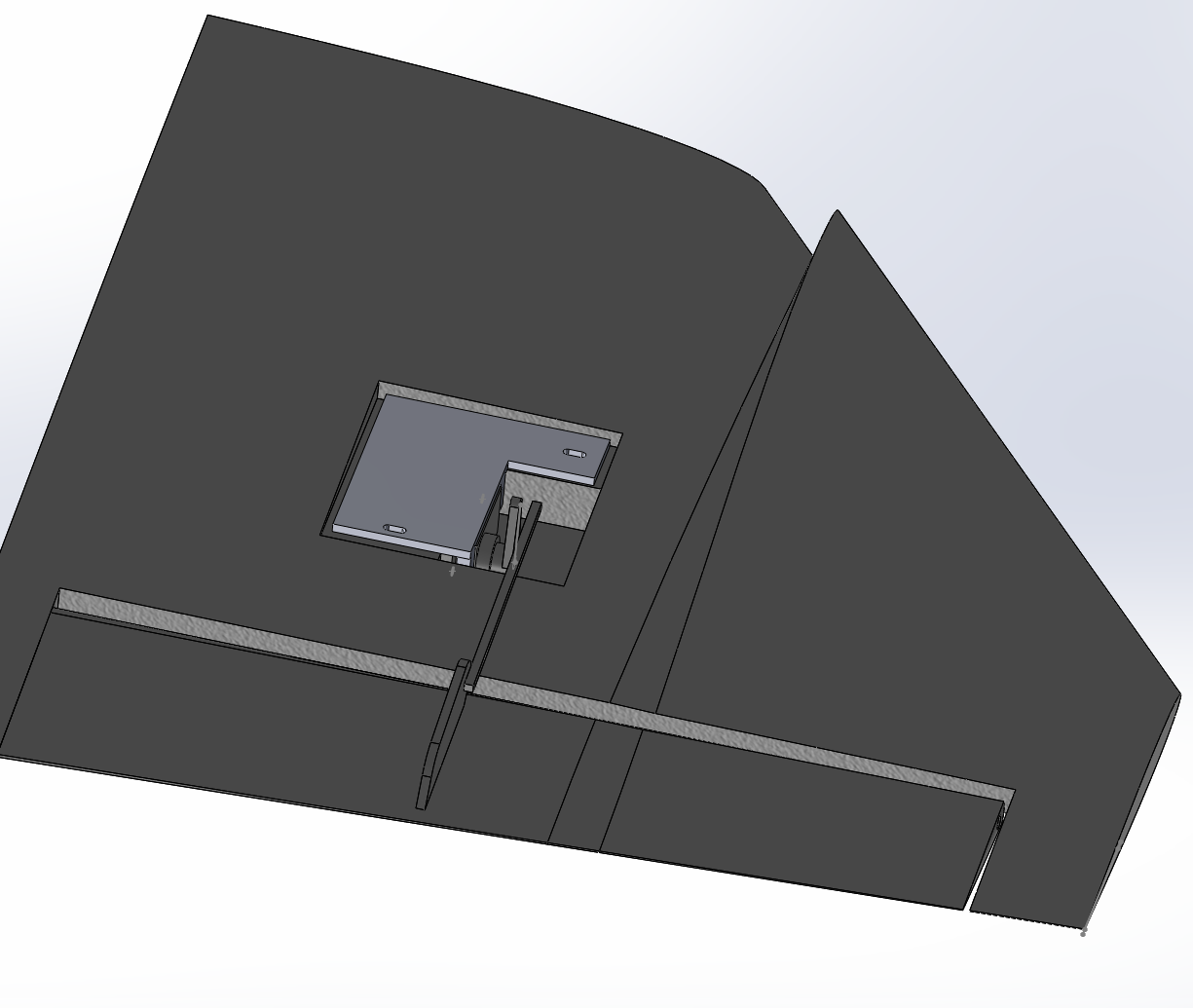
im currently thinking about how to attach the servo onto the wing. my current plan is to make a lid thing that i will screw into the wing that holds the servo still with some pigs that go into it's screw holes.
Screenshot_38.png

Screenshot_39.png


I'm not a huge fan of it but it is the best way i can thing of since just screwint it in at that angle isnt possible. I'm a little bit worried about how the airflow will behave over it altough im pretty sure it shouldn't be a problem. just incase im going to try and make the lid follow the surface of the wing.
 

Mr Man

Elite member
im currently thinking about how to attach the servo onto the wing. my current plan is to make a lid thing that i will screw into the wing that holds the servo still with some pigs that go into it's screw holes. View attachment 248167
View attachment 248168

I'm not a huge fan of it but it is the best way i can thing of since just screwint it in at that angle isnt possible. I'm a little bit worried about how the airflow will behave over it altough im pretty sure it shouldn't be a problem. just incase im going to try and make the lid follow the surface of the wing.
You could also just glue in the servo like E-flite.
 

NeonGreen

Member
also here is another part of the plane that i printed out just to try out the movement of the canards. The green you see is the lw-pla that i bought and the purple is just some normal pla that i had at hand.