Phantom V3 - DLG - Design Build

bracesport

Legendary member
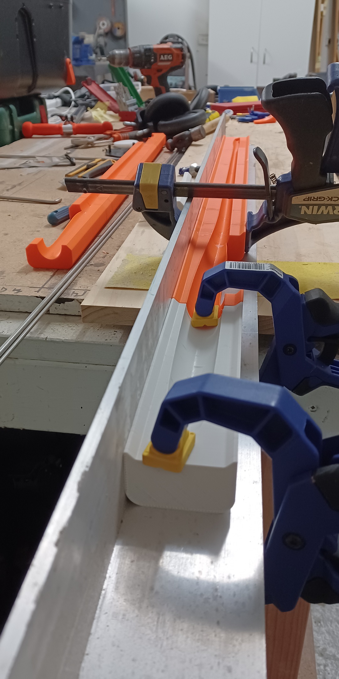
The last pieces of the puzzle are in place!
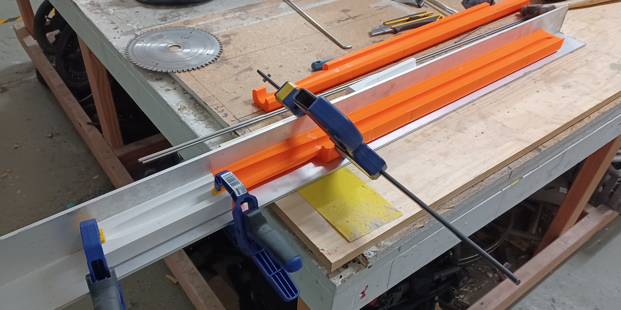
IMG_20220721_083112_(2160_x_1080_pixel).jpg
IMG_20220721_083124_(1080_x_2160_pixel).jpg
 

bracesport

Legendary member
These latest prints worked out well for the 22mm spinner and motor mount - I used Polycarbonate for the prop mount so it is very strong - hopefully these will be the final parts!

IMG_20220721_090946_(2160_x_1080_pixel).jpg
IMG_20220721_091011_(2160_x_1080_pixel).jpg
 
  • Like
Reactions: Inq

bracesport

Legendary member
I put in a 50gsm FG 'outer skin' layer to get a good surface contact with all the fiddly sections of the mould - I also added two layers of 40gsm UD - after curing I will do the proper layup with CF and join the moulds with a balloon - the nose section will be FG.

20221124_073231.jpg
20221124_094241.jpg
20221124_094258.jpg
 
Last edited:

bracesport

Legendary member
Getting close to laying in the CF.

I was planning to put a tube inside the balloon and stretch it out to 1m to lay into the fuse but I could not get the balloon to play ball!

I had an idea to just stretch the balloon by clamping one end at the tail and fitting the other end with the silicon tube (for inflating the ballon) doubling as the seal at the neck - I dry fitted the moulds and pumped up the balloon up and it all worked well - I also plan to wax the balloon to assist in release.

To make the layups I will pre laminate the CF and partially cure it before trimming out the forms and putting them into the moulds - I may vac bag them flat, but I will see how the laminating goes with the roller first.

20221129_104249.jpg
View attachment
 

bracesport

Legendary member
I cut the platforms and marked the curvature to sand the nose profiles - I have a wee angled sander at home which I forgot to bring today.

20221201_094934.jpg
20221201_115352.jpg
 

bracesport

Legendary member
The LE of the tail feathers are sanded - I used my adjustable angle sanding block to rough out the LE angles - next it was onto the mounting sleeves which were tacked in with 5min epoxy using the alignment jig then filled with thickened epoxy under some mylar to smooth them out - hopefully there will be minimal sanding afterwards.

1.jpg
2.jpg
3.jpg
4.jpg
5.jpg
6.jpg
 

bracesport

Legendary member
It held pressure for 5 days in the mould - this morning it took about half an hour to get it out of the moulds - I would have to say it is a bloody success! I am stoked as I thought is would most likely be a huge failure - the undercut removable sections in the wing saddle and V tail faring all popped off without a hitch!

In the end the mould became sacrificial after I broke a couple of sections - I am not too unhappy about that as I would improve the design and re-print the moulds if I do another one! There was no wax on the moulds, just two coats of PVC.

I drilled the pilot holes for the V tail mounts using guide holes in the moulds before removing those sections - I need to cut open the canopy section to remove the balloon.

A very happy chappy!

a.jpg
b.jpg
c.jpg
d.jpg
e.jpg
f.jpg
View attachment
h.jpg
i.jpg
j.jpg
k.jpg
l.jpg
 

bracesport

Legendary member
Yay the balloon came out easily after cutting out the canopy hole - my canopy cover needs a bit of work to fit properly but is all heading in the right direction - the tail mount sleeves are in and I took the opportunity to dry fit the feathers - next the tails need to go into the vac bag and I can tidy up the mounting sleeves.

To add the wing mount screws I will cut an access hole between the mounting screws and to get the alignment I will 3D print another jig - at some stage I also need to cut off the tip of the nose and dry fit the motor - in the back of my mind I have been concerned the motor mount might be a bit small.

This is also the slimmest fuse I have made so it will be fun to fit the servos - I will probably put the tail servos under the wing but we will see where things are at with the CG first.

20221213_080707.jpg
20221213_081310.jpg
20221213_082155.jpg
20221213_081421.jpg
20221213_081518.jpg
20221213_081559.jpg
20221213_081625.jpg
 

bracesport

Legendary member
I pulled the tails out of the bag and they are good! My rookie mistake was the mylars have a Gloss side and a Satin side so I ended up with Satin tops and Gloss bottoms - I really like the Satin so I will 1200 grit sand the bottoms to match.

Otherwise they are great - the Kevlar hinge looks to have worked well - I did not press in any relief to seat the Kevlar in the foam so there is a slight raised impression - next time I will go the extra mile there.

I think I will cut in the hinge then add a lick of epoxy to the raw foam edges.

V happy.

20221220_082729.jpg
20221220_082937.jpg
20221220_083025.jpg
20221220_083045.jpg
20221220_083054.jpg
 

bracesport

Legendary member
Nice - dry fitting the motor looks to be on the right path - I will need to do a bit more work to fit the tails and the wing to determine the hardware locations and CG, but I am quietly liking the progress so far - using CAD and moulds and 3D printing is awesome for dimensional accuracy.

20221222_072900.jpg
20221222_073458.jpg
20221222_073750.jpg
20221222_073805.jpg
20221222_073813.jpg
20221222_074017.jpg
 

Inq

Elite member
Some more tweaking - 80% slimmer fuse section in vertical direction - the purple nose section that houses the servos is a 3D printed part that is removable and will be better for different configurations and modifications (including a prop version) - the 3D printed section has a 7mm CF tube for stiffness - the flaperon pushrods are now in perfect alignment for a straight run - battery up front - Rx through slot at the base of the 3D printed part - looks pretty good I think.

View attachment 220909 View attachment 220910 View attachment 220911

With you having refinements at the ultimate end of the spectrum using carbon-fiber/epoxy cured in female molds and gorgeous streamlining, I find it odd that you would leave the horns outside in the slipstream. Is there some technical/logistics reason you don't use short torque tubes on the aileron hinge line and have the horns on the inside... just a few millimeters inward?
 

bracesport

Legendary member
FYI, I have that on my Phantom 2

For this build I am first using one of my old BAMF-1 wings - but having said that, it would be possible to convert that as well!

With you having refinements at the ultimate end of the spectrum using carbon-fiber/epoxy cured in female molds and gorgeous streamlining, I find it odd that you would leave the horns outside in the slipstream. Is there some technical/logistics reason you don't use short torque tubes on the aileron hinge line and have the horns on the inside... just a few millimeters inward?


402694_d89c7649bb25eb9e66c583e04e76b692.jpg
402695_b636e49c64e4412406b7ead9110c95a2.jpg
 
Last edited:

Inq

Elite member
Just now finding your thread and being newer than when it started, I'm going back through it. Apologies if I ask a question that you answered later. If I don't ask it when I find it, I'll forget. :rolleyes::sneaky:

Some more CAD tweaks - this time I have made the wing joiner a 'V' for the dihedral and tapered it to match the shear web - I think it will better integrate with the shear web and be a little easier to make - I am planning laminated popsicle sticks covered with UD CF and a CF braided sock for the joiner - the sleeve will be CF braided sock and joined in with the shear web and wing skins - there will be an end cap for the wings to further integrate the joiner sockets - well that's the theory anyway.

Really top notch aerospace industry techniques you're using! (y)

I see you mentioning shear webs, caps and assuming you're optimizing lay-ups for those. Since you find 170 grams heavy and seeing this post, I wonder... are you doing structural analysis? Closed-form, Mechanics of Materials or numerical, FEA? If so, what kind of margins are shooting for? Do you have any specifications on your CF?

Cool stuff! :cool:
 

Inq

Elite member
I have been thinking more seriously to make the Phantom III an F5K ship - my tweak on it is to go V tail with pull strings

I've been thinking of designs using pull strings. What do you do to account for the changes in length as a function of stretch or even CTE? I've seen some of the both positive and negative CTE on some of the strings... nylon, monofilament, PE braided line, Dyneema, polyester, etc. Do you re-tie every flight day or have something that will give, like springs?
 

bracesport

Legendary member
I am aiming for an AUW around 270g (240g would be nice) - no analysis - just doing everything by feel!

Just now finding your thread and being newer than when it started, I'm going back through it. Apologies if I ask a question that you answered later. If I don't ask it when I find it, I'll forget. :rolleyes::sneaky:

Really top notch aerospace industry techniques you're using! (y)

I see you mentioning shear webs, caps and assuming you're optimizing lay-ups for those. Since you find 170 grams heavy and seeing this post, I wonder... are you doing structural analysis? Closed-form, Mechanics of Materials or numerical, FEA? If so, what kind of margins are shooting for? Do you have any specifications on your CF?

Cool stuff! :cool: