Phantom V3 - DLG - Design Build

bracesport

Legendary member
Here is the dry fit - the good, the bad, and ugly!

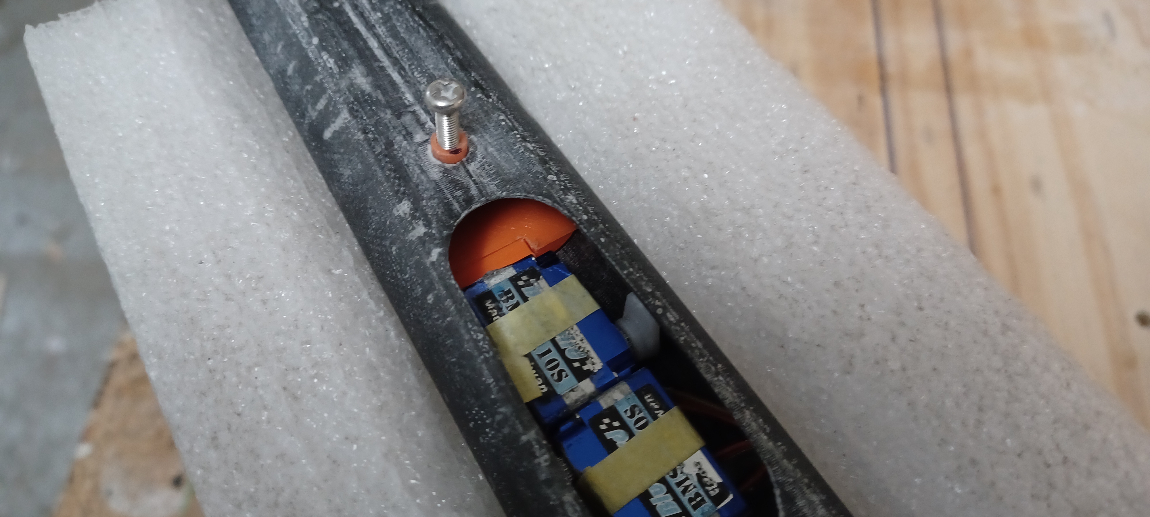
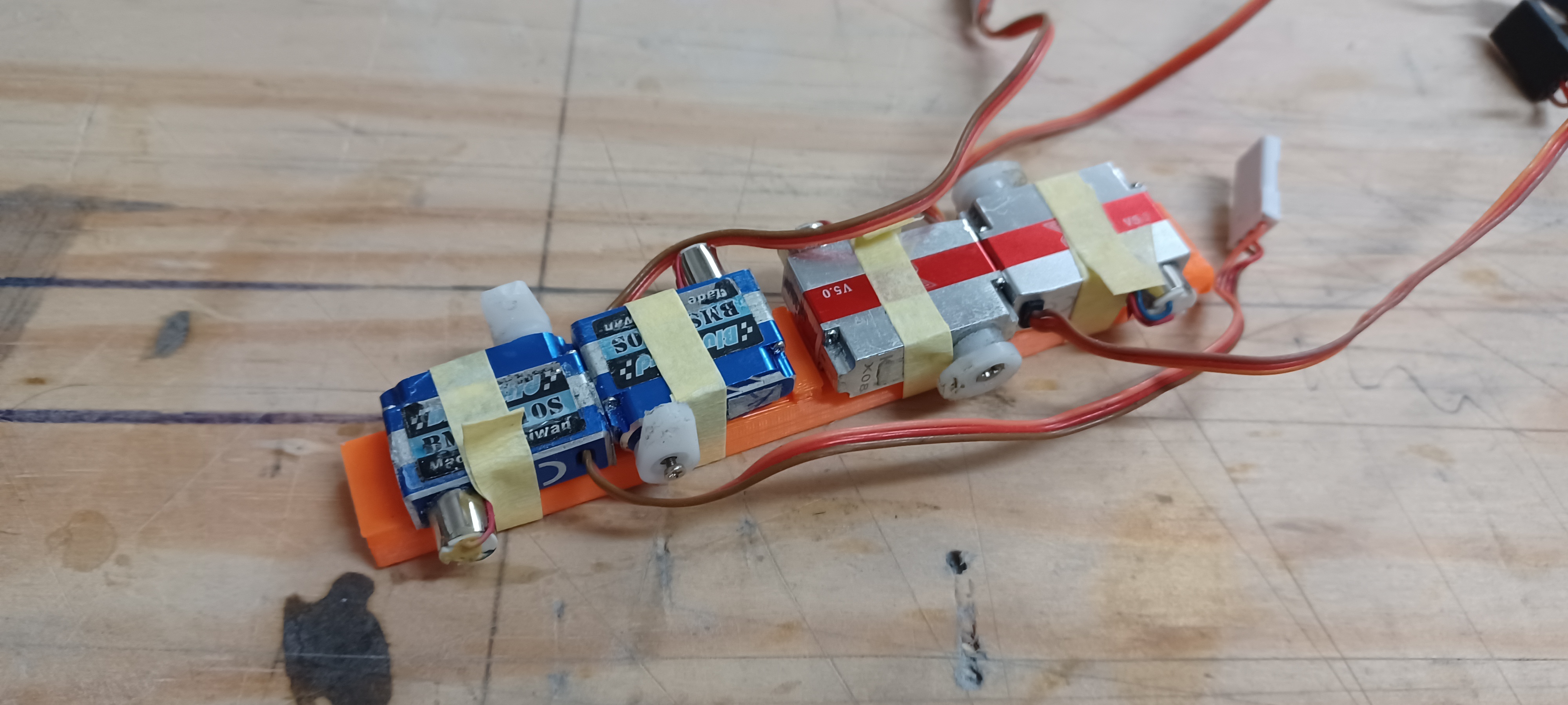
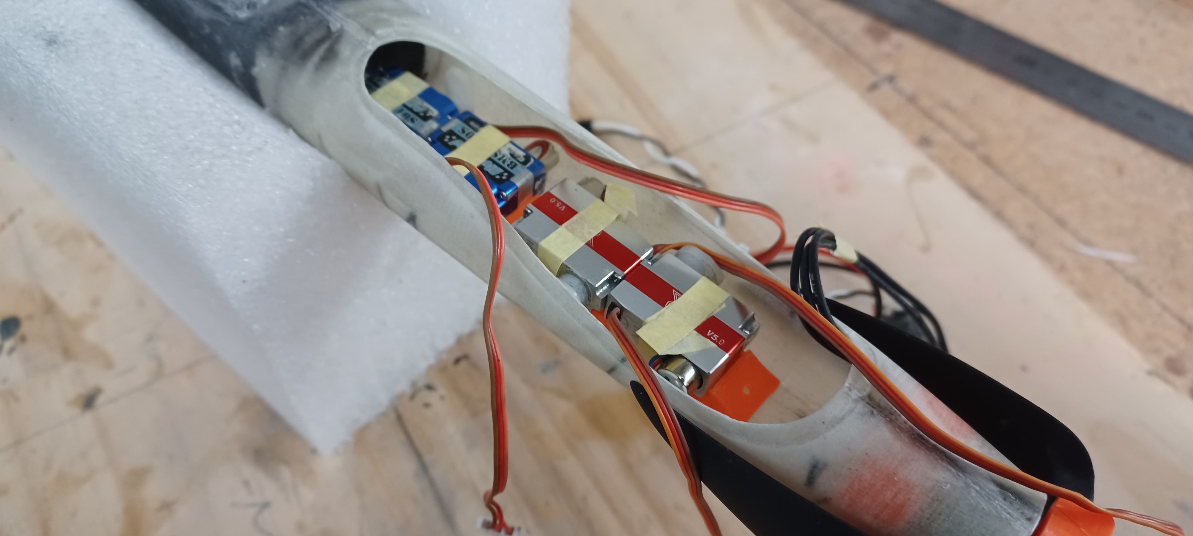
Actually, not so bad and not so ugly - the servo tray fits in through the fuse canopy and can slide back into position - it will be an interesting push rod install but as just mentioned by 'floatdog' I can consider a pre-built jig - my initial plan was to set my servos into the tray, fix the tray into the fuse, set my adjustable pushrods with a slow cure epoxy.

I am running two batteries - one for the motor and one for the Rx/servos - having the two batteries gives me the nose weight I need without just adding weight - the batteries and the servo tray weigh similarly but the batteries provide a more concentrated forward weight.

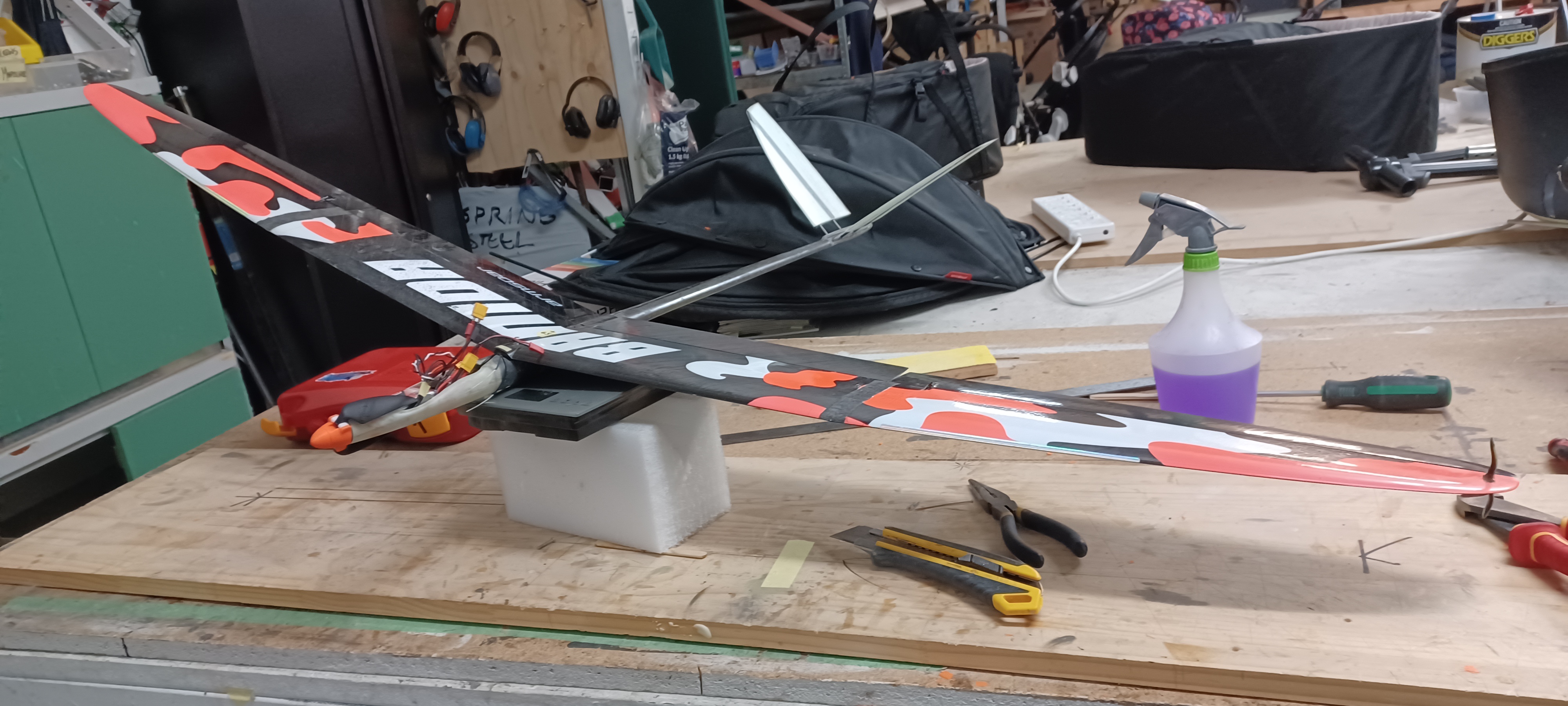
I will still try and remove a tad more tail weight - this is a 6 servo, motored, twin battery setup and compared to my old BAMFzilla at 275g I have currently added a further 75g with the added hardware - my fuse is 20g heavier than a factory fuse (not too bad) and my tail is a bit heavy so overall it is looking pretty good.

I have marked the balance point on the fuse with all the gear installed so I can see any improvements as I tweak the tail and add the hardware permanently.
20230214_094338.jpg
20230214_094507.jpg
20230214_094609.jpg
20230214_094744.jpg
20230214_094809.jpg
20230214_095033.jpg
20230214_095107.jpg
20230214_102238.jpg
20230214_102902.jpg
 

bracesport

Legendary member
I have tweaked the CAD for the servo tray to help hold the servo wires to keep things neat - I have added two hooks on either side that the wires will pass through - once printed the dry fit will make it clear (I hope)!

Screenshot 2023-02-15 at 3.44.58 PM.png
Screenshot 2023-02-15 at 3.47.28 PM.png
3.jpg
Screenshot 2023-02-15 at 3.48.01 PM.png
Screenshot 2023-02-15 at 3.48.48 PM.png
Screenshot 2023-02-15 at 3.49.03 PM.png
 

bracesport

Legendary member
I always feel good with new parts on the printer - can't wait to see how they turn out - I am also printing a cap of sorts to convert the servo arms for the tail into rollers.

Screenshot 2023-02-16 at 9.18.01 AM.png
 

bracesport

Legendary member
I tacked the rearward mounting plate into the fuse and did a dry fit of the servos onto the servo frame - the servo arm collars fit well and look great.

20230216_125057.jpg
20230216_122750.jpg
20230216_130909.jpg
 

bracesport

Legendary member
I am just tidying up the wing saddle before sorting the push rods - it is a pretty good fit but the front needed some filler - the BAMF wing has a raised front section (mates with the BAMF fuse) that I will remove if the glider is successful.

20230220_123306.jpg
20230220_123312.jpg
20230220_123510.jpg
 

bracesport

Legendary member
The wing released from the tape and the nose of the saddle is shaping up nicely and I have cut the pushrod outlets - I saw a guy building a massive train layout and he used PVA to secure his wires so I did the same here.

20230221_072438.jpg
20230221_073517.jpg
20230221_075613.jpg
 

bracesport

Legendary member
Chipping away on the tail feathers - next, I need to bend up some springs and make the flap push rods - getting there though.

20230221_083342.jpg
20230221_083850.jpg
20230221_125003.jpg
20230221_125714.jpg
 

bracesport

Legendary member
A quick pushrod test - originally I was going to make the pushrod ends separately and glue them into a carbon tube to get the length right - with this test I just made a one piece wire and it works well too - because I am running my push rods internally I need to have guides to prevent them falling inwards out of the control horns - but I also need some flex to allow me to get the wire ends in and out of the horns - I could add collars onto the wire ends once through the horns but they can get lost - I have some ideas to try!

20230223_085112.jpg
20230223_085139.jpg
 

bracesport

Legendary member
here is the final proposal for the spring system to support the pushrod wires - if there is any unwanted flex I will add a CF tube over the pushrod wires - flaps are mostly stationary and with use are pulling more than pushing apart from holding the flaps stationary.

IMG_0009.jpeg
 

bracesport

Legendary member
Here is the dry fit of the tail and the internal pushrods for the flaps on the poly wing - the springs are done for the tail surfaces and they feel pretty good - there is a small amount of play in the push rods sideways so I am going to make the cups a tad smaller and push them further into the fuse closer to the flap horns - the function seems good regardless.


IMG_0016.jpeg
IMG_0017.jpeg
IMG_0018.jpeg
IMG_0019.jpeg
IMG_0020.jpeg
IMG_0026.jpeg
IMG_0028.jpeg
IMG_0022.jpeg
IMG_0023.jpeg
 

bracesport

Legendary member
Any progress is progress..

I am starting the fit out of the servo tray with the push rod spring fitted - the pull string wires are attached at the servo end and will be completed at the tail end - well, everything seems to fit including two batteries - there is a GRX8 on board to handle the 6 servos and motor - I am starting work on the pull string outlets in the tail which will get some sleeves added to protect the strings.

IMG_0040.jpeg
IMG_0041.jpeg
IMG_0044.jpeg
IMG_0045.jpeg
IMG_E0046.jpeg
IMG_E0047.jpeg
 

bracesport

Legendary member
OK so in go the taileron pull strings - they need to be attached at the rear as the servos are not accessible for tying off the thread when in place - I fed a rod in from the tail end and CA glued the pull string to it to pull back through to the tail end - all good twice in a row!

IMG_E0059.jpeg
IMG_E0060.jpeg
IMG_E0061.jpeg
IMG_E0062.jpeg
 

bracesport

Legendary member
I fitted the wing and the the push rods are working really well for the flaps - it is great to have the push wires running internally and they seem well supported by the plastic spring - popping the wire ends into the control arms was a breeze.

The wing surfaces are mostly setup just needing some micro adjustment - new I need to sort out the motor.


Screenshot 2023-03-09 at 10.54.15 AM.png
 

bracesport

Legendary member
I had a niggle getting the motor to run - the answers are always more simple than you think - it occurred to me the GRRX8 might be in SBUS (no CH7 output) - and it was!

FYI - the current manual is incorrect for switching SBUS to PWM - you actually need to use the jumper on pins 1/2 and re-bind it to turn off SBUS (that took some head scratching)!


bracesport

Legendary member
It is all together now and wow is the canopy tightly packed - I could do better if I hardwired it but it will do fine for a maiden - I need to add some whisker tubes, a lick of paint on the nose, and I might need a tad more nose weight - something to double check tomorrow.

WechatIMG2170.jpeg
WechatIMG2171.jpeg
 

bracesport

Legendary member
I am tidying up the install - the whiskers are in and the antennas are routed nicely - the ESC is secured - a bit of paint on the nose can't be underestimated at this point!

IMG_0109.jpeg
IMG_0110.jpeg
IMG_0111.jpeg
IMG_0112.jpeg