Trying a different approach to a STOL

L Edge

Master member
High alpha and STOL devices are a kick to fly. Some work, others not so. I chose a real tough one . The DR Chinook.


Looking at some of the devices that he offers:
1) a raised leading edge of the wing
2) leading edge slot
3) endcaps
4) elevator that is angled
5)flap caps
6) oversize elevator control that produces a ground wake
and so on.


What I am going to do is build super light with a wing without any bracing and adding other devices that I have explored.

Since no plans are available, going to use some research and experimenting that I have done. Being "old school", out comes the paper, slide rule and drafting tools. This is what I have come up with using the gut feeling, study the figure over and over and going crazy. Finally I put the paper work away and now for the build.
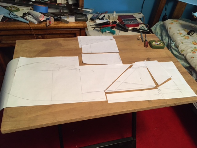
STOL.JPG


So that is the starter. Leaving the wheel setup off for now to see if it will fly by chucking it.
 

L Edge

Master member
TD:
This gave me a a lot of info on elevated wings. See how touchy the wing is in wiping you out at high AOA and slow speed. When wing stalls, you see how fast the results are. Got a device to change that. Hope it works.


L Edge

Master member
Did some rethinking on how to duplicate model and have come to the conclusion that I need to have landing gear. So inside of fuse needs to redesigned to take impact of landing. Working that out in my head.

So this is the tail feathers I built. Imagine the elevator pushing up the tail when throttle is first added. Rudder control is there too. In fact, go to video at 1:10 and see the sequence of what he does with the movable elevator and when the flaps come down to approaching takeoff.

I have explored brakes and had success using the sequencer of the DX9(on a transport) doing no brakes, oscillating for taxi and full brakes for takeoff) . This would be a good example to use brakes.

Don't expect this model to look sharp. I can design, but artistic, I am not.

tail feathers.JPG
 

L Edge

Master member
Today, landing gear is needed.

Tailwheel should allow turns. Weight aft of CG is lots of down leverage. Motor is aft of wing. So net result is build tailwheel with no swivel on first shot. Using "KISS" method, and after 6 hrs of trying, built the lightest which works the best. The tail feathers will sit on the top bracket, glued to bracket and rudder will be glued to tubing. Whet tighten, slotted tube will keep tail wheel in place.


tailwheel.JPG


Side view:

Allowed enough clearance so down elevator can almost touch ground.
Drilled hole in tubing and inserted rear wheel wire frame in and got a wooden plug to keep fixed. Slotted bracket will be crimped to insure not rotating wheel.

tail(side view.JPG


So far, all parts are from the trash boxes that I have kept over time. This is a Excell heli tube that I have laying around. If you have the passion, strip the model that you and others trash.

Now to revise the whole front end.
 

L Edge

Master member
Today, working on fuse. With landing gear and tail wheel going on, try to tie everything so it doesn't crumple(hard landing, not crash) and using the tube as main support. So going slow to figure out.

Made wing and re-enforced it with 1/8 carbon tube and will add more structure when working ailerons and flaps.

Since width of fuse is small, will need wide gear so that it doesn't wing tip and dig in and damage itself. Learned that from making transports.

Use weights, square and ruler to jig things when gluing. Make it real simple to get 90 degree and appropriate location for foam/wood.

fuse sides.JPG
 

L Edge

Master member
Today, finished using balsa wood for main frame. I am hoping to tie landing gear, rear tube, and wing all together. One thickness wasn't enough, ended up do 2 layers because a hard takeoff or landing will probably trash it. Going to use nylon bolts and nuts (in case it shears off) hoping to save the project) to retain wing and gear. Heck, with a tilted wing and elevated tail, who knows what is going to happen.


frame.jpg


Scratch projects with no plans sure take of a lot of thinking(sometimes days) ahead and if wrong, ruins the device.
 

L Edge

Master member
The title of the video above relates to the word of "Slowest". That's were I was and scratching my head and didn't know what to do. So jumped ahead and started sorting, cutting out things. Got the landing gear to interlock to the frame and tail tube as well as strengthening the wing support. Added motor and voila!! Cut the tail tube 3" off and put it together. At present, everything is adjustable.

Things bad:
Need to shorten tube some?
Angle of Wing is too steep.
Motor needs to be out further.
Video only source to truly scratchbuild and never allows for angles or good detail to work off..

Things good:
Like motor behind wing when taking off or landing. It will really have to flip over before making contact.
Angle of tail boom doesn't look bad for landing gear/tail boom/ground level.
First used hot glue to hold tail feathers to cleaned tail boom surface. Noticed that's not good. Tried Super glue dripped on boom and got a good result between metal and hot glue and foam didn't get eaten away so it doesn't tear off in flight.(I hope)
Like that airflow should catch under elevator and it should rise by itself with throttle being advanced. Much like an Ekranoplan.
I sure hope I can add brakes to explore programming using the throttle so as I advance, to release brakes, then drop flaps and do a STOL takeoff. ?(How about landing and having a mode 3 where throttle is reduced partial brakes are applied)


chip.jpg
 

Taildragger

Legendary member
The title of the video above relates to the word of "Slowest". That's were I was and scratching my head and didn't know what to do. So jumped ahead and started sorting, cutting out things. Got the landing gear to interlock to the frame and tail tube as well as strengthening the wing support. Added motor and voila!! Cut the tail tube 3" off and put it together. At present, everything is adjustable.

Things bad:
Need to shorten tube some?
Angle of Wing is too steep.
Motor needs to be out further.
Video only source to truly scratchbuild and never allows for angles or good detail to work off..

Things good:
Like motor behind wing when taking off or landing. It will really have to flip over before making contact.
Angle of tail boom doesn't look bad for landing gear/tail boom/ground level.
First used hot glue to hold tail feathers to cleaned tail boom surface. Noticed that's not good. Tried Super glue dripped on boom and got a good result between metal and hot glue and foam didn't get eaten away so it doesn't tear off in flight.(I hope)
Like that airflow should catch under elevator and it should rise by itself with throttle being advanced. Much like an Ekranoplan.
I sure hope I can add brakes to explore programming using the throttle so as I advance, to release brakes, then drop flaps and do a STOL takeoff. ?(How about landing and having a mode 3 where throttle is reduced partial brakes are applied)


View attachment 231343
how do you plan on doing brakes? interested.
 

L Edge

Master member
how do you plan on doing brakes? interested.

Keeping it simple.
brake.jpg


Servo will be hot glued to my landing gear. The servo arm will be metal and ground flat or to the shape of the tire.

Will write 2 mixes in the transmitter(left and right wheel) to a 2 position off brake and on. ATV will set off position and each on position will have the left and right rotary switches adjust the compression between the tire and the servo.

In the DX9 radio, I used 2 sequencers(programming steps) to have a 3 position switch for scale setup. My transport would set the nose brakes, start one engine and 5 seconds later, start the second. Raise the throttle slightly, I then would switch the sequencer to oscillate the brake to taxi out at a fixed speed. Then switch back to brake on for takeoff. Increase throttle and then switch off brake.

Here is the brake sequencer.


L Edge

Master member
Really having no idea what this build is going to do since it has no plans(scratch building which I enjoy), did a lot of trying to figure ahead of what might happen. Angle of wing wrong, where's CG, control lengths for ailerons and flaps, too heavy, etc, Well, there is the point you have to "just do it".

Cut last piece of dupron(6mm and added what I have left to lengthen wing) and did initial carbon rod across the bottom. Added flaps and aileron to wing again using video above for reference. Built out motor mount so to clear flaps and using a APC 9" prop to power it.
sideview.jpg


Here is front view.

front view.jpg


Hope there is enough ailerons. Wonder if differential aileron mixing will help?
Will need to fiberglass center with epoxy and use 2 nylon bolt/nuts to retain wing to fuse.
Notice two rods on table that I am going to use from landing gear to wing(1/2 way out on each side and some sort of flat plate) to keep foam wing from bending. Total of 4 rods. Keeping total weight in mind, will add more carbon rods or carbon strips as I near end of building to prevent bending or twisting in outer portion.
Add leading edge device to wing.
Mount servos and try to finish wing.
It will be interesting if I have to cut more black tubing off to shorten length of plane to keep it to scale and balancing becomes an issue ?
Placement of battery is another of my concerns related to CG and height..

I found that plane balances as of right now just behind balsa fame on black tube. Only thing to add in tail area are the control horns, 2 servos or control cables. So far, it's manageable.

If you see something wrong or can improve it, let me know.
 

L Edge

Master member
Continued wrapping up the tail by getting the two servos mounted as you can see. I initially was going to use cables to the fuse and run servos there. Not long enough, still hope I don't end up tail heavy.
tailwing.jpg


Next came the mounting of the aileron and flap servos. Made flaps 15" long and ailerons 8 & 1/4". Installed larger carbon tubing(hot glue) to reduce bending and torsion. In the center area, used some bass wood and balsa wood(epoxy glue) to transfer wing loading and going to use 2 bolts to hold wing to fuse.

20 wing.jpg


Next comes the hard part.
1) Getting wing mounted to fuse so it is mounted that each wing tip on each side is equal.
2) Get wing 90 degrees to fuse.
3) Make sure elevon is in same plane as wing by sighting from elevator to wing.
4) Get wingtips to elevon tips equal distance.
5) Drill mounting holes and retainer nuts.

Version one seems to get a lot of "hanger rash." Do yours$
 

Piotrsko

Master member
Since it's a flat wing some sort of droop LE Might be called for or a slat. At around stall only the bottom will be doing lifting so up aileron will be kinda useless. This going to fly nose low?
 

L Edge

Master member
Since it's a flat wing some sort of droop LE Might be called for or a slat. At around stall only the bottom will be doing lifting so up aileron will be kinda useless. This going to fly nose low?

Yes, I am using a NACA device which changes the flow pattern across the wing and keeps it stabilized. It works on swept wing airplane as well as a flying wing with no vertical (endplates) and I just tested it out on modified Sponz's "wonder" plan where his models have a straight wing and it handles high angles of attack that handles turbulent swirls near the ground.(have videos) . So I am going to find out if it does.

I am trying to duplicate, so will it fly nose low?, hoping the wing at 20 degrees will counteract that. If you watch his video, flaps are dropped at start, plane leveled as it rolls, pulls up elevator and then brings flaps up . Watch the landing in what he does and also his hover and off course the wind speed and direction.

I also put a more powerful motor/prop to account for extra drag. Keep asking me questions, more I know, the better the chances for a success. Chinnok is what I call a scratch build.

 
Last edited:

L Edge

Master member
Moving ahead, got the servos on for flaps and ailerons. Now fasten the wing to the fuse with blind nuts and working on bracing the wings to the landing gear. Did double bracing to prevent bending and twisting.

Added end plates to the flaps as well as the wing to duplicate the builder's idea. Interesting idea.


fuse.jpg
 

tamuct01

Well-known member
Lucas Weakley did a design where he could adjust the angle of incidence as needed from his plane. It's a cool experiment:
 

L Edge

Master member
Lucas Weakley did a design where he could adjust the angle of incidence as needed from his plane. It's a cool experiment:

Hey, thanks for the video. As soon as I button up the design, I am going to put the order of ground test runs(not flight) and explain why to see what others in this forum think. Have a number of options and why I chose it. Want to see what others think.
 

Piotrsko

Master member
What resulted from your osprey swing wing experiment a while back? I don't recall you getting satisfied results, but im old and forget stuff
 

tamuct01

Well-known member
What resulted from your osprey swing wing experiment a while back? I don't recall you getting satisfied results, but im old and forget stuff

It's still taking up space in my office. I had to find a replacement for the rotor mount to the wing (the original was 3d printed). I did find an aluminum solution but had to redesign the rotor mount plates a bit. The biggest problem I've had is time (not enough of it.). I also bought a Shapeoko 4, so I've been getting used to creating stuff with it. I might go back and cut the nacelle side plates from G10 fiberglass instead of 3d printing them. We'll see how long this version lasts.