Twin edf SU-27

NickRehm

Member
Cool build! Try setting all D gains to 1/2 of what they are stock, then dial in the P gain on the ground so full transmitter stick deflection gives ~30 degrees of control surface deflection. I think that'll get you flying fairly well. Then you can increase P gains in ~10% increments for more control authority, until you get oscillations. At that point you can either dial the P gains back to a safe level, or increase D gains in ~10% increments alongside the P gains. At a certain point, you'll reach the upper limit for both P and D, so its a good idea to find that limit and set the P and D gains to ~70% of it. This should give best stability and maximum performance without PID oscillation madness

But good call programming in the different flight modes--always good to have a safe (unstabilized!!) flight mode you can fall back on when things get weird
 

Flitedesign 3d

Elite member
Here is a video of the 4th flight since I thought it was worth sharing. It was with thrust vectoring enabled for most of the time. At this point I think my flying skills are kinda inadequate to showcase what this thing can do. It was only the fourth flight though, so there is still plenty of room to get more comfortable with it. Also the stabilization, which already is much better than on the first flight, can most likely be further optimized, I'm working on it. Just to make it clear, this model, just like its predecessor, flies very stable and easy on manual mode, and stabilization is absolutely not needed. I'm using it because firstly I'm interested in it and secondly it will most likely be helpful on some 3d maneuvers for which I don't have the skills for.

I also measured the static thrust against a scale, got a reading of 2600g. That's 200g more than on the su-27. I can think of 3 reasons for this: I'm using cheat intakes right in front of the fans, the engine ducts and intakes are slightly larger than on the 27 and I'm using a third more battery capacity which should reduce the voltage sag on high loads thus giving higher max power. Anyhow, thrust to weight ratio is over 1.2, at the beginning of a flight anyways, so that's cool.

Regarding the plans, I've been refining them and catching as many bugs as I can and they're looking good. I'm back at uni and spare time is nonexistent so I'll put them out asap, next weekend at the latest.


Flitedesign 3d

Elite member
I just uploaded the plans to my github, you can find them here. If you haven't used github, to download the files click "code" and "download zip". Build instructions will come as a time lapse video, once I get that edited...
 

L Edge

Master member
A well thought out design and it flies nicely. Can't wait until you do a knife edge across the field.
Thrust vectoring is a different animal. It even allows an EDF to fly in a dome with ease.

Check out what it allows you to shoot for.


Oldrover TJ

Active member
I'm looking forward to building this. Now I need to get some thrust vectoring nozzles!

...maybe a few 6s batteries too
 

speedy7385

Active member
Flitedesign 3d, thanks for the beautiful design and plan. Start 3d printing all the STL files.
Are there any STL files for the Vector Nozzle? It seem to be missing from the zip package.
Thanks
 

Flitedesign 3d

Elite member
Check out what it allows you to shoot for.
That's so cool, I would need to spend couple of years on the field just flying to be able to do that :)
Are there any STL files for the Vector Nozzle?
No, the nozzles are not printed, they are generic 70mm thrust vectoring nozzles, I bought them of aliexpress for about 14€/piece. I thought about making printed nozzles but it's difficult because of tolerances and layer line induced friction
 

speedy7385

Active member
That's so cool, I would need to spend couple of years on the field just flying to be able to do that :)

No, the nozzles are not printed, they are generic 70mm thrust vectoring nozzles, I bought them of aliexpress for about 14€/piece. I thought about making printed nozzles but it's difficult because of tolerances and layer line induced friction
Awe, I see. Thanks, will look that up.
 

iwpublic

Member
@Flitedesign 3d
out of curiosity would you please share a photo or sketch of your Batt/ESC wiring? I suppose you are hooking up all lipos in parallel for capacity and reduced amp draw from each pack. But are you driving both ESCs also in parallel from the same source or does each ESC have its own set of lipos?
Asking for a friend :cool:
 

L Edge

Master member
That's so cool, I would need to spend couple of years on the field just flying to be able to do that :)

No, the nozzles are not printed, they are generic 70mm thrust vectoring nozzles, I bought them of aliexpress for about 14€/piece. I thought about making printed nozzles but it's difficult because of tolerances and layer line induced friction

What really makes it simple for the maneuvers is the head holding gyro, once you get into the acrobatic action, you are basically flying it hands off and if it needs trim, then you pulse your control to adjust. How do you think the heli guys can do all those stunts, take away the head holding command, and you would see major damage.

Want some fun?, make a simple foam dual bird, add the gyro to the TV nozzles and hh command, bet you will be hovering within the hour.
 

iwpublic

Member
Here, I drew up a complete wiring diagram, I'll add it to the plans set as well. It's two batteries per esc but I bridged the sets together in case I want to fly with 3 batteries
Many thanks.
So all batteries are hooked up in parallel due to the brigde. I'd do it the same way as if each ESC was connected to its own pack/set of packs one will face different RPM which leads to unintended yaw.
 

Flitedesign 3d

Elite member
Hello

I just finished and uploaded the build guide videos for the su-30. Sorry it took so long, I began my masters degree this autumn and I haven't really had the time, energy or motivation to do it faster. I also updated the plans folder, I added the thrust tube files that I had forgotten.

Good luck and have fun on the builds, keep me updated! :)

Part 1:

Part 2:
 

iwpublic

Member
Many thanks @Flitedesign 3d for your efforts, passion and community thinking despite your real-life duties. Kudos to you!

I am in the middle of the build process - this time 100% scale but again a few mods in order to address my quite flexible EU depron material (no paper coating).
Will keep you posted!
 

iwpublic

Member
@Flitedesign 3d It seems there is a minor issue in the plans.

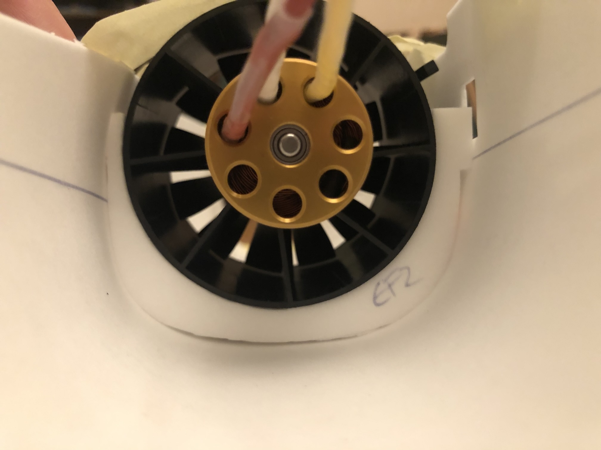
Formers EF1/2 (both, foam cut and 3d printed version) do not fit into ES4. If EF1/2 alignment tabs are put into ES4 cutouts there is plenty of space at the bottom (see pic 1).
IMG_0802.jpeg

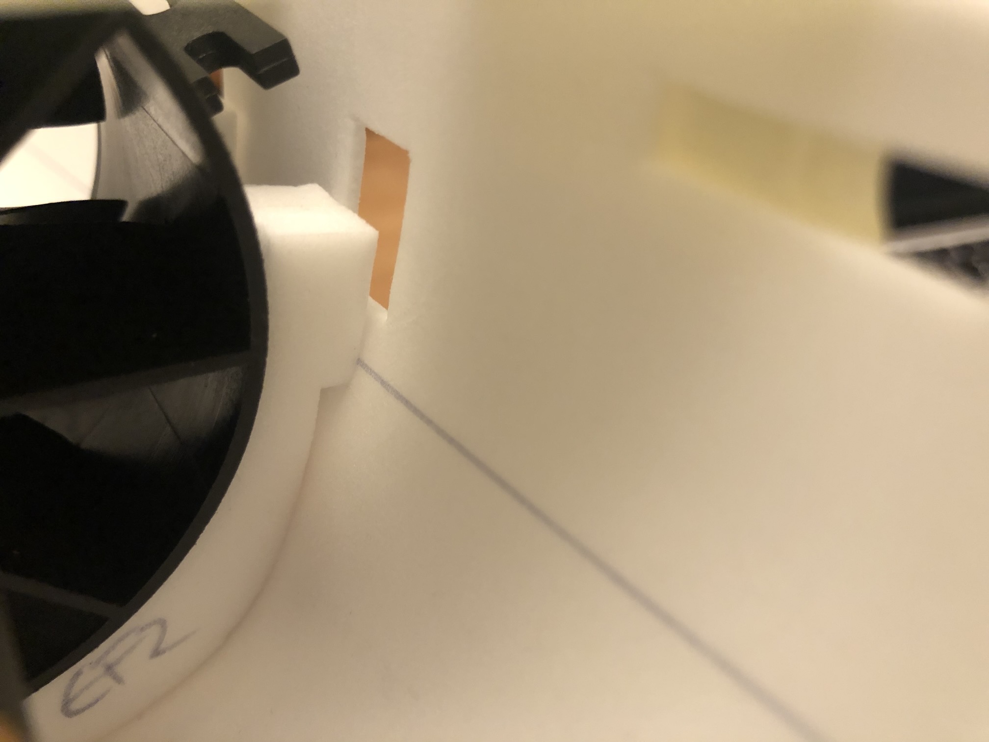
If the formers EF1/2 are aligned with ES4 then either side of the cutouts is too high.
(see pic 2+3)
IMG_0803.jpeg

IMG_0804.jpeg

First I thought I messed up the printing scale. But I measured 3x and reprinted @100% scale.
EF1 "circumference" is ≈17.3cm.
ES4 "circumference" at EF1 position start to end is ≈18.5cm

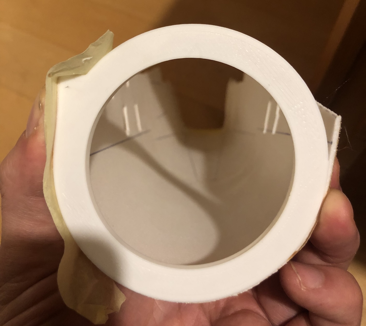
Same effect is at EF3. If aligned with the inner side of ES4, the radius of EF3 would be too small to have ES4 ending up correctly on the outer side...
IMG_0807.jpeg

Now I could move the cutouts 0.6cm lower on each side.
Alternatively the space at the bottom could be filled by additional material on EF1/2.
But I am afraid this has an impact in the thrust line, hence, your advice would be much appreciated!
 
Last edited: