1m Beech Staggerwing D17S

aelflyer

Member
Main retracts are in.

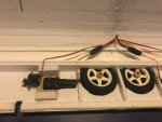
Ok, the main retracts are now in, working, and they fully retract recessed into the wing.

This has been a bit of an adventure with a lot of head scratching and false starts.

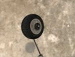
I started with the PZ-15094 servoless retracts and the struts/wheels from the RocHobby Staggering. Unfortunately the tire was too thick, so I changed the wheel to the Du-Bro 2.5" Micro Sport Wheel. It turns out that 2.5" diameter is exactly the scale size of the wheels on the Staggerwing, though I had to give up on the wheel pants.

I created some wheel bushings using extra plastic that came from a pack of control horns (for the inner bushing) and a chunk of paint stirrer stick (for the outer bushing). I used the original snap-ring that came on the RocHobby struts to hold it all together.

Ideally (for the next person building this plane), we could find this 3mm wheel strut without having to waste money on the RocHobby wheels and wheel pants that don't work with this plane. Anyone know where to find these struts by themselves?

1.jpg 2.jpg

After a days of test-fitting in the wing, I finally settled on building a wood mount for the retracts out of a mix of 3/32" and 1/16" hobby plywood, screwing the retract unit in from the bottom to give myself a little more room in the wing (it's a tight fit in there). The main support that is inside the wing is 3/32" plywood and the pieces that stick down to form the retract mount is made of 1 piece of 1/16" and 1 pieces of 3/32" plywood. It's all hot-glued together, glued into the wing, with extra glue around the edges inside. I'm temporarily mounting the retracts with extra servo screws, but the final (longer) screws will go through all 3 pieces of wood.

3.jpg 4.jpg 5.jpg 6.jpg

Here they are in action:

Next step is to install the flap servos and then add reinforcements in the wing to make up for the cuts (especially to the spar) and add foam to connect the wood retract mounts to the upper wing for extra support.
 
Last edited:

aelflyer

Member
Lower wing is done: main retracts and flaps

Lower wing is now done. A few details:

- Added foam spars on top of retract wood mounts to hopefully provide reinforcement in case of hard landings by distributing the load to the upper wing surface.

- Added foam spars around the wheel wheels to make up for foam removed from the main spar and lower wing surface.

- Routed wires to front side of spar to get them out of the way of the retract mechanisms.

IMG_0792.jpg IMG_0791.jpg IMG_0788.jpg IMG_0789.jpg IMG_0790.jpg
 

aelflyer

Member
Carbon spar in lower wing

The wing ended up needing reinforcement across the middle where I cut part of the spar to make room for the wheels. I could have used wood, but I had a carbon fiber spar handy, so I used that. I'm not 100% sure it was needed, but it significantly stiffened up the wing. A bit of hobby plywood would also have been fine.

I slit the foam of one of the spar pieces, scratched up the carbon spar, and filled the slit with hot glue from top and bottom.

IMG_0793.jpg IMG_0796.jpg IMG_0794.jpg
 

aelflyer

Member
Final wing weights

Upper wing (ailerons): 137g
Lower wing (main retracts and flaps): 233g

All 4 servos are FliteTest 9g servos with Du-Bro linkage stoppers.

I'm counting on 80" of thick airfoil wings to generate a lot of lift! :)

IMG_0798.jpg IMG_0800.jpg
 

aelflyer

Member
Video of finished lower wing in action

Last post this morning, here is a video of the finished lower wing's retracts and flaps in action:

 
Last edited:

aelflyer

Member
Tail retract done

Thanks, DamoRC!

Tail retract is now done. That means all 9 servos are in and working (tail retract, 2 main retracts, 2 flaps, 2 ailerons, elevator, rudder).

I started from a fixed tail wheel assembly, though I only ended up using the wheel and collars from this kit.

All drill holes in this build use the same 1/16" drill bit.

I bent a 1.4mm pushrod to form the axle and wheel mount. I attached it to a plastic control horn by drilling two new holes in the control horn and bending the pushrod through the holes (see pictures).

I then drilled a hole through the thickest part of the control horn, as close as possible to the arm, at 90 degrees for the pivot. The pivot axle is made from the same 1.4mm pushrod going through the control horn, anchored with wheel collars on each side, and stuck into 2 pieces of 3/32" hobby plywood. (see pictures).

I drilled the hobby plywood using the bottom tail foam piece as my angle template.

The entire rear tail assembly weighs ~10g.

I then hot glued the plywood to the fuselage, lining it up with the top of the fuse. I measured the required throw on the control horn to make sure a 9g servo with a long arm could do it. It was fine---it needs about 2.5cm of servo travel for full retract/extension.

To keep weight out of the tail, I mounted the tail retract servo under the top wing. This is a 9g FliteTest servo with a long arm on it. As a pushrod, I wanted it to be rigid and light, so I used a 3/16" square wood rod. It attaches to the servo arm and control horn on the retract via threaded rod threaded/glued into the end (drilled out with same 1/16" drill bit), and a clevis threaded onto that piece (see pictures).

I tried my best to match scale for the location of the tail wheel and amount that the wheel protrudes from the fuselage when extended.

Please ask questions if any of this is not clear. As I was trying to figure it out as I was building it, I didn't make plans as I went, but I really hope someone reproduces this and I'm happy to help design plans for it.

IMG_0807.jpg IMG_0808.jpg IMG_0809.jpg IMG_0810.jpg IMG_0811.jpg IMG_0812.jpg IMG_0813.jpg IMG_0814.jpg IMG_0815.jpg IMG_0816.jpg IMG_0805.jpg IMG_0804.jpg IMG_0817.jpg IMG_0818.jpg IMG_0819.jpg IMG_0820.jpg IMG_0826.jpg IMG_0827.jpg IMG_0828.jpg IMG_0829.jpg
 
Last edited:

aelflyer

Member
Here's a quick video of all 9 of the Staggerwing's servos wiggling: tail retracts, main retracts, flaps, ailerons, elevator, rudder:

 
Last edited:

aelflyer

Member
Close to final weight w/out battery: 716g. This includes everything except battery, foam that forms cowling and the bottom fuselage foam piece. This is less than the FT Storch, which has a 59" wing span. I've got 80" of wing span, but biplanes don't get a perfect 2x lift due to conflict between the wings. Nonetheless, even if I get 1.5x the lift of 1 wing, I'll be at the same wingspan as the Storch so it should fly :)

IMG_0834.jpg
 

aelflyer

Member
Airplane Jig

When scratch building, where cuts are sometimes not perfect, I often struggle to get the wings exactly perpendicular to the fuselage. My spouse suggested I make an airplane jig simply by drawing a big cross on a large piece of paper. Then line up the center of the fuse and center of wing on one line and the leading edge of the wing on the other line. Might also add a 3rd line to align the horizontal stabilizer. Hold everything in place with miscellaneous heavy objects.

Why didn't I think of this sooner? :/

jig.jpg
 
Last edited:

aelflyer

Member
Lower wing mount

I decided to mount the lower wing in a way that is strong, but semi-removable. The reason I want it removable is that Fadi and I are planning to re-design the fuselage with a more scale/curved/less-boxy design, and I don't want to rebuild the wings. To accomplish this, I built two braces / wing attachment points out of 3/32" plywood, medium CA glue, and foamboard. Then glued those into the bottom of the fuselage.

After the braces were in, I lined everything up on my "airplane jig," tacked the wings in-place with a couple small smears of hot glue on top of the wing joint, then drilled holes from the bottom of the wing and mounted screws using 1/32" wood as washers.

I say semi-removable because I'll only take the wings off if we build a new fuselage, and they are mounted with a little bit of glue on the top joint.

Next step is to align the top wing relative to the bottom. Getting closer....


IMG_0843.jpg IMG_0848.jpg IMG_0850.jpg IMG_0849.jpg
 

aelflyer

Member
Upper wing aligned

With the plane back on the jig, this time upside down, I glued 4 pieces of BBQ skewer into the leading and trailing edge of the wing as alignment guides. The upper wing is held on with rubber bands.

Wing struts. I realized that these don't need to be very strong, they are mostly for looks and a small bit of rigidity. We'd originally spec'd them as 2 sheets of foam for strength, but a single sheet gives a more scale look. I rebuilt these and trimmed them to get the upper wing level. They'll be glued to the lower wing and velcro to the upper wing because the upper wing is removable.

They aren't glued in yet, so they are dry-fit in these pictures with removable tape. The cowling is temporary in these pictures, and is missing a foam ring on the front. I'm still not happy with how the cowling looks, so a bit more work to do there. The thrust angle isn't set yet, and lots more details to work through before it flies.

IMG_0852.jpg IMG_0853.jpg IMG_0851.jpeg
 

aelflyer

Member
CG?

Perhaps - but it's getting there, nice work!.

DamoRC

Thanks, DamoRC! It's definitely an interesting journey with step-after-step of new-thing-I-haven't-built-before.

I'm starting to look at CG estimates. I have two quite different data points, but I'd appreciate advice on how to estimate CG for this biplane:

1) RickP was nice enough to modify his Staggerwing Phoenix simulator model to match the dimensions/weight/power of my plane. We tested it out in Phoenix and found that a good CG is a bit back from the leading edge of the aft (top) wing. This makes some logical sense insofar that it is between the centers of lift of the two wings. We admittedly need to play around more with airfoil selection in Phoenix to try to get close to my model.

2) The RocHobby 1.0m Staggerwing model has the following to say about CG (here's a link to the manual). "The recommended CG for your model is 60mm/2.4" forward of the leading edge of the main wing." If I understand their drawing correctly, the "main wing" is the top wing and the CG is on the leading edge of the fore (lower) wing:

[Edit] I'm pretty sure the RocHobby has a typo. If I measure 1/2 way between the "25% of chord back from leading edge" of both wings, I get a CG right at the leading edge of the aft (top) wing. This is exactly where the CG is marked in the drawing below. However, the text says something different. I'm pretty sure the text is wrong.

IMG_0856.PNG
 
Last edited:

aelflyer

Member
I'm starting to look at CG estimates.

I contacted JBing, the FT community member that built the original foamboard Staggerwing. He had this to say about CG for the Staggerwing:

"The way I normally set the CG as a starting point is 25% back from the leading edge. In the case of a biplane with staggered wings, I measure the 25% point of each wing and set the CG at the middle between the two points. For example if a wing were staggered 1" the CG would end up being 1/2" behind the 25% point of the forward wing. In this case it would be the lower wing. Transfer that point straight up to the top wing and you should get the plane to balance a little nose low from that point."​

Doing this math on my model looks like this:
  • Wing chord = 6"
  • Wing stagger is 2.125” from LE to LE
  • CG is 50% between CG of each wing
  • Midline of 25% estimate is 2.56” (6.5cm) back from LE of lower wing
  • Midline of 30% estimate is 2.86” (7.3cm) back from LE of lower wing

This CG position is just behind the LE of the top wing, making it impossible to do a CG balance check using the top wing. Therefore I balance the plane like it were a low-wing plane, upside down with CG marks on top of the bottom wing.
 
Last edited:

aelflyer

Member
Tail retracts with bottom of fuse installed

Finally installed the bottom of the fuselage. It includes a cut-out for the tail retrac and an openable hatch to access the linkage stopper screws to trim the elevator and rudder.

IMG_0878.jpg IMG_0990.jpg
 
Last edited:

aelflyer

Member
Rounding the leading edge of the wing tips

In discussion with previous Staggerwing builder, JBing, he mentioned that his Staggerwing was a nice flying airplane, but it did have a tendency to tip stall. That made me realize the wing tips are elliptical, which brought back memories of my FliteTest Mini Cruiser.

The Mini Cruiser was my 5th FT build, and it was by far the most difficult to get to fly well. For the longest time, my mini cruiser was an angry and mean airplane with nasty tip stall tendencies. I showed the plane to a retired Boeing engineer one day at the flying field. He told me there was a simple fix, and he turned out to be right. He advised me to blunt and round the leading edge of the FT-style under-cambered wing tips by adding a 2nd piece of foam (or a strip of 3/16" x 1/2" balsa) to the underside of the leading edge of the wing tips, shape the new under-piece to taper into the wing on its trailing edge (see pictures below), then sand top and bottom of the leading edge tips nice and round. He assured me this would smooth out the air flow over and under the tips and greatly reduce chance of tip stalls.

The difference was amazing. My FT Mini Cruiser is now a gently, predictable, fun, sporty little plane with a gentle nose-down-level stall, and it lands nice and slow. It went from being my worst flying plane to one of the best in my hangar.

Given that experience, JBing's cautionary tale of his Staggerwing, and the fact it has elliptical wing tips, I decided to do the same treatment to all 4 wingtips of the Staggerwing. This plane might not need this treatment, but it's good/cheap insurance.

Pictures below show the process.

1) Cut strips of foam to match the shape of the leading edge of the wing tips. Use a hobby laminating iron at ~325 degrees to shape these strips into the semi-airfoil shape. Do this by melting the trailing edge of these strips with the iron. You'll know you have the right temperature if you hear the foam melting/popping beneath the paper when you hold the iron in one place. Don't get it too hot or you'll warp the foam. I used a rolling action with the iron on the edge of my work bench.

2) Glue these ironed strips to the leading edge of the wing tips.

3) Sand the top and bottom of the doubled leading edge into a smooth, blunt shape. I started with 320 grit on a sanding block, then finished it with 400 grit.

IMG_0863.jpg IMG_0871.jpg
IMG_0872.jpg IMG_0877.jpg IMG_0875.jpg
 
Last edited:

aelflyer

Member
Cowling

Finally finished the engine cowling. The original design used a circular ring of foamboard wrapped with a tube made of posterboard. I didn't like how the round cowling meshed with the rectangular fuselage, so I set out to improve it.

I started by taking the posterboard tube (a rectangular piece) off the old cowling, cutting slits in it every ~3/4" all the way around, then fitting this around the nose of the fuselage. I then taped the slats back together to get a sort of oblong (egg-like) cone shape.

IMG_0930.jpg

I then laid this out flat as a pattern and traced around it to make a clean version of it.

I made the foamboard piece by putting the new posterboard cone on the plane and tracing around the outside to give myself a template for the foamboard.

IMG_0932.jpg IMG_0931.jpg

I added posterboard to the under-side to completely cover the underneath of the fuselage, then slit the posterboard to make a battery hatch. The hatch latches with a BBQ skewer and small strip of velcro.

IMG_0935.jpg IMG_0936.jpg

Here's the final cowling installed.
IMG_0934.jpg
 
Last edited:

aelflyer

Member
Wing/stabilizer alignment

Time to set the final wing/tail angle-of-attack alignment. As per Dan Crew's suggestion, I'm aiming to have the top wing and horizontal stabilizer at the same angle-of-attack (AOA), and the lower wing at a slightly increased AOA. The idea is for the lower wing to stall first in a right-side-up stall, drop the nose, and resume flying before the upper wing stalls.

Below is the setup I used to measure the alignment of the 3 surfaces. I'm guessing at what line to use for the wings, using roughly bottom-of-leading-edge to bottom-of-trailing-edge as the reference line. I don't know if this is aerodynamically correct but its the best I can do.

IMG_0982.jpg

This is the picture after re-aligning the top wing. I ended up placing a BBQ skewer shim under the trailing edge of the top wing to get the AOA to match the HSTAB. The lower wing ended up with ~1.5 degrees of increased AOA relative to the upper wing (computed by measuring the distance between the two straight edges resting on the wing: arctan(rise/run) gives the angle).

Hopefully the end result, combined with the rounded wingtips, is a plane with gentle stall characteristics.