Extruder upgrade - e3d Titan

jhitesma

Some guy in the desert
Mentor
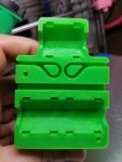
So close....this is really driving me crazy.

I took a few days off and focused on other projects, went camping and spent time enjoying my family. Then last night decided to give this another go. I think a big part of the problem I'm having is my layer fan is failing. So I'm not getting sufficient cooling and that's making the issues with printing this worse.

So I gave it another go with cura last night, I changed my layer height slightly (I had been printing at 0.25mm but 0.24 and 0.26 are a better match for the pitch of my leadscrews IIRC so I gave 0.26 a go.) I also rotated the part 45 degrees on the bed to try and make the steppers work in unison hoping it would make it less likely that one would skip. And finally...I enabled supports (ugh.)
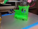
20180114_234905.jpg

It came out, no layer shifts! But I sliced the wrong model...this one is missing the last wire tie-down I added :(
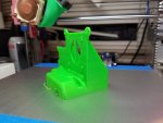
20180114_234908.jpg

Nuts, oh well. I can live without that.

At least it stayed adhered to the bed and it printed without shifting...now...let's tackle that support:
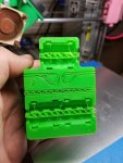
20180114_235115.jpg

Ugh, I hate support. So much of it. It even put support in the belt paths and the little 3mm holes:
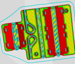
Screen Shot 2018-01-14 at 11.52.07 PM.png

:( This is going to suck....but....

20180115_000315.jpg

That actually cleaned up pretty well. The 3mm holes were a serious pain to get the support out of, but for the most part it wasn't that bad since cura does much easier to remove supports than slic3r. Unfortunately the easier looking supports in the mounting holes didn't go as well:
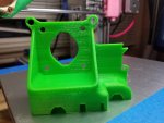
20180115_000322.jpg

One of my IR sensor mounting holes broke removing it's support :( And while it's less obvious so did both ears for tying wires off :(

Even so...I can probably live with this. At least enough to install it and use the new extruder and layer fan to print a better one.

Except....the support has come back to bite me :(
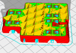
Screen Shot 2018-01-14 at 11.52.22 PM.png

Can you see the problem?

The tunnels where the zip ties run to mount this to the linear bearings....it put support in them :(

I've tried a few things to get in there and knock out the support...but it's far enough in that I can't seem to get any kind of tool that strong enough to dislodge the support up through the curve.

Grrrr.

Going to give cura another try today...but this time with support only enabled when it touches the bed. It won't help support the top which may cause the jump at the top to come back...but hopefully the 45 degree rotation will help avoid that. It will mean the things that broke removing support won't have support and I'm fine with that since they print fine without support anyway.

Never expected it to turn into this big of a project to install this extruder :p Can't get over what a pain this part is turning out to be.

If it still fails on this next try I may attempt something totally different. Go back to the original design of this mount, swap to the longer mounting screws that came with the titan, and just print a piece like this (The 2mm thick purple bit):
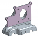
Screen Shot 2018-01-15 at 10.33.08 AM.png

Which can sandwich between the extruder and mount to give me a place to mount the IR sensor. I'm not convinced that adding my IR sensor mount is what made this so hard to print...but...it was right after I added that when I started having major issues....one more go at the one piece tonight first though.
 

jhitesma

Some guy in the desert
Mentor
Well, after 3 pages of failure it looks like tonight I finally get to install my new extruder!

20180115_225527.jpg

I didn't install it last night because by the time it was done printing and I got the support removed (most of it was easy, one of the 3mm holes was a serious pain) I was too tired to tackle the installation. I want to make sure I'm ready to do this since once I start taking things apart I won't be able to print any replacement parts if the need arises!

20180115_225544.jpg

In some ways it looks more compact than my current setup...in others...not so much. It's shorter...but it's wider. The IR sensor is considerably smaller than the inductive sensor, and the layer fan being on the back is less obtrusive than on the front. Really curious to see how it ends up doing.
 

jhitesma

Some guy in the desert
Mentor
Well, got close last night but don't quite have it printing again.

Easy start - pull the extruder fan off. I should have taken a before photo to show how much dust and hair and dirt were on the blades...it was nasty:
20180116_205958.jpg

You can get a feel for how nasty it was by how much crud is on the extruder behind it once I removed the hot end:
20180116_210326.jpg

The hot end heat sink itself was covered in dust as well, which surprised me as I give this fan and the heat sink a zap with some compressed air every couple of weeks.

Few minutes later things start getting really scary...it's not a printer anymore :(
20180116_211316.jpg

All the bits that are coming off:
20180116_211208.jpg

It's not quite a fair weight comparison since it includes the wires and most of them aren't actually weighing things down. And the photo earlier from when I weighed the new extruder and stepper didn't include any wires or the cooling fan (which I didn't have yet at that point.) But I'd still say it looks like about 100g of weight being pitched from my X axis with this upgrade.

Anyway, time to start putting this new extruder in place finally!

First test assembly reveals that my mockup wasn't quite accurate. With the hot end positioned the way I wanted it for the wiring it hits my IR sensor:
20180116_213332.jpg

I actually had planned for the wires to come out between the hot end and the IR board - but there wasn't enough room. So I rotated it this way which put the wires out the front - only to find that it won't clear the IR board that way. Bummer. But solvable. I could move the IR board out a bit, I've currently got 17mm between it and the hotend:

20180116_213710.jpg

Making that distance larger won't hurt anything. But would be annoying to change at this point so what I chose to do send the wires out the right side instead:

20180116_213439.jpg

Kind of defeats the point of the wiring tie-down points I added to the design :( Going to have to come up with a different idea for those.

Speaking of the IR sensor...since this is a RC forum I'm guessing most of you will spot the "design flaw" I hadn't noticed on the IR sensor until I went to wire it up:
20180116_221856.jpg

I skipped buying the wire for the IR sensor because I figured "heck I've got a bunch of servo extensions, why spend more on another?" Except I wasn't thinking fully clearly. This needs a female/female and extensions are female/male. So I need to modify one of my extensions before I can finish wiring up the sensor. I didn't have time to do that last night so that's the first reason why I'm not yet printing.

And due to the already mentioned "design flaw" I had to modify the extension anyway since the positive wire isn't in the middle. I like this warning from the designer:

Warning: the sensor is fairly tolerant to mis-wiring, including having the 3-pin connector reversed. However, if you apply power with the Vcc and Gnd connections swapped over, you will destroy the microcontroller.

So it's fine to swap the connector...as long as you don't actually apply power :p So to me it's not really tolerant of having the connector reversed at all.

The last wire tie-down I added which I was considering to be optional and figured I probably wasn't going to use...turned out to be the only one I actually could and did use:
20180116_223040.jpg

(That would be it on the far left where the IR sensor wires and the cooling fan wires are tied together.)

Overall it's looking good. The cooling fan seems to be positioned well - and when I powered it up it was not only way quieter than my old cooling fan it also moved considerably more air. I am a little worried about the IR sensor though...I may not have mounted it quite low enough. I can't test that until I finish wiring it up though:
20180116_223105.jpg


At first I thought it seemed WAY lighter and easier to move on the axis...then I realized I hadn't attached the belt yet so it wasn't connected to the stepper:
20180116_231359.jpg

I got the belt half re-connected before calling it a night so hard to say just how it feels, This design includes a belt clamp so the belt is fairly easy to install...but it's upside down from my old x-carriage so I had to totally reposition the belt. Would be easy if I just turned the machine around but there's too much junk under it for me to deal with that right now so I'm just playing contortionist and stretching behind which makes it a bit trickier to get the belt installed good and tight.

I did try extruding some filament:
20180116_231418.jpg

But it was just by hand :( Something else is wrong that's causing me to not get movement out of the stepper. I did try giving it some commands to extrude and I did hear a bit of humming from the stepper....but no movement.

Since this is geared the stepper needs to be reversed from what I had before, and also since it's geared the steps have to change quite a bit. My old stepper I ran 100 steps per mm. With this e3d suggests trying 837 steps as a starting point!

I didn't bother to change the direction yet since I just wanted to see it extrude - even if I had to do a retract move to get it to extrude. But I wasn't getting motion out of either. So...need to do some digging as to what exactly is wrong. I did hook up one of my other spare steppers and it did move - but then didn't move in the other direction so it seems something is goofy.

Hopefully tonight I can make the final wiring connection on the IR sensor, flash a newer Marlin with config updated to 837 steps and reversed extruder...and then figure out the final little issues so I can start printing again.
 

jhitesma

Some guy in the desert
Mentor
Oh yeah...one good thing from last night...turns out my existing fan mount does just barely work with the extruder rotated this way. So at least I've got that going for me :cool:
 

jhitesma

Some guy in the desert
Mentor
Well...not quite printing yet :(

But...it's close. Very close.

I got the IR sensor wired up. I went out to my shop to look for a F/F extension last night and couldn't find one...but I did find a current sensor I'd been looking for to put in an explorer I'm setting up for FPV with a seppuku running dRonin for stabilization and eventually GPS semi-autonomous flight. At lunch today I went back out there to look for an extension again...and saw the current sensor sitting on my desk only to realize it came with an extension just like I was searching for. I don't really need it how I'm going to use the sensor so - got my extension!

Wired up the IR sensor, powered up the RAMPS board and...it blinked 4 times indicating it had power and had initialized in analog mode (which is all the RAMPS can handle) so that was good. Moved my finger under it and sure enough the light came on! So it seemed to be working.

But...when I did a M119 to check the status of my endstops....Z was showing as triggered :( So I have to reverse that. Guess I'll update firmware next!

I had to change Z_MIN_ENDSTOP_INVERTING and Z_MIN_PROBE_ENDSTOP_INVERTING which were both true (like all my other endstops)
to false. While I was in there I also updated my E steps from 100 to 837. I then adjusted my probe offset - X went from 37 to 17 and Z went from 1.7 to 2.75 (just a guess...and I'm actually using 2.8 currently despite what my firmware was configured for since I've updated it in EEPROM.) And finally I inverted my extruder since the gear reduction means it now has to turn in the opposite direction.

You can see the changes if I diff the config file. Lines in red are removed and lines in green are added:

Screen Shot 2018-01-17 at 11.18.30 PM.png

With that all done I flashed it. Which...was tricky. I'm using octoprint and my printer can't really reach any of my computers by USB. But the plugin for octoprint I was using to flash stopped working for some reason. I did some debugging...couldn't figure it out. Uninstalled it and installed a new flashing plugin instead...which didn't work at all. So gave up and took a notebook over to the printer to flash that way. Eventually I got it done.

Next I hooked up the belt on the X axis and snugged my tensioner. At this point I figured I'm ready to test!

So...first thing I did was check the endstops with M119 again to confirm Z is working. Next I tried to home X/Y and quickly ran into two problems. My X now moved in the wrong direction and even if it had gone the right way my endstop holder isn't going to work anymore as there's nothing on the X carriage that will reach it anymore. Doh.

But that backwards X had me scratching my head. I didn't change anything in the config or wiring...why is it backwards? Finally it hit me. The old X carriage the loose ends of the belts attached at the top with the continuous section beneath, but this new X-carriage is reversed with the ends on bottom and the through section on top. It's upside down so it reverses the motion! I flipped the stepper plug for X and that's now moving the right direction.

I still have to hit the X endstop manually since the carriage won't hit...but I can mostly home X/Y now.

Then I got gutsy and tried Z. Which resulted in me crashing the head :(

Turns out my actual v6 hotend is a few mm longer than the mockup I used in CAD. The IR sensor appears to be triggering at the right difference...but my nozzle sticks past it more than expected. So...I'm going to have to rig something up to move the sensor down lower until I can print another carriage with a longer mount. Great...I get to fight with that print some more :p No time to rig that tonight...but I'll probably just take a bit of scrap lexan or PVC sheet and just stick it on with some 3M outdoor tape for now. Will be an ugly hack but should get me going well enough to print a final X-carriage.

So...back to the extruder!

Last night it wasn't doing anything for me. Just humming slightly. I checked the current on the stepper and found that my E0 current was at 0.30v which was half the Y at 0.6 but higher than the X at 0.12 (Z is running a different driver so the current measurements are calculated differently and don't really compare.) Well...I decided to just try turning it up and see if I could get the stepper to move. And sure enough as I slowly turned it up the stepper started to move! I'm a little freaked out though because I had to turn it all the way up to 1.1v to get the stepper moving reliably. Which seems crazy high. But the stepper didn't get nearly as warm as my old one...so <shrug> we'll see how it does.

I made a mark 120mm above the extruder and told it to extrude 100mm....it extruded...but I could barely see the filament move. Hmmm.

Oh yeah...EEPROM. Even though I updated the steps in firmware my EEPROM is overriding that with my old settings when the board boots. Did a M92 E 837 (to update the steps) followed by a M501 (to update the EEPROM with the new setting) and redid the test. This time it extruded 95mm of filament. So I'm close. I'd adjust the steps...but it looked like the stepper was skipping a little at a few places. So instead I'm going to adjust the current some more.

Before I do that though I'm going to swap from the A4988 that's on it currently to a DRV8825 since the DRV's have a voltage divider that results in easier math to figure out the current setting. (they also do 32 microsteps instead of maxing out at 16 like the 4988's...but I don't really need that since then I'd be running almost 1700 steps which is just crazy talk.)

So tomorrow I need to swap that driver and finish adjusting the current for the extruder. Rig up an extension for the IR sensor, and maybe rig something up for the X endstop as well. Then....maybe if I'm lucky I'll get to try printing with this thing finally!
 

LitterBug

Techno Nut
Moderator
My XYZ Hotend upgrade is moving along slow. I have what appears to be a good fit with the E3D V6 and printed holder and have started on removing the stock hot end. Need to pull the carriage off and finish it up now. The design I'm working at is "supposed" to work with the stock firmware. So we'll give that a go first, then work on updating the firmware to repetier later.

Also have a new 40mm noctua fan for the MP Select Mini V2. Which means of course that the stock fan is working fine again. Have a mount printed up, but need to mod the mount holes. They were only 1mm in the .stl. WTH? ah well, we'll drill it and make it work with the soft rubber mount hardware.

Cheers!
LitterBug
 

jhitesma

Some guy in the desert
Mentor
Starting to get tired of projects getting ugly on me :(

Current state of my printer:
20180119_082158.jpg

Yuck. So how did it come to this?

Well, I started by swapping the extruder driver for a DRV8825. The A4988's the math to figure your current varies depending on which value of resistors are on the boards, I don't remember which value is on my steppers and didn't feel like digging out a magnifier to try and figure it out...and even if I did the math isn't what I can do in my head. The 8825's on the other hand are simple, you read the reference voltage and double it to get current. They also tend to run cooler and quieter in my experience and can do 32 microsteps instead of just 16...though with the 0.9 degree stepper from e3d I really don't need or want 32 microsteps. With all the step jumpers installed on the ramps (for 16 microsteps with the A2988's) you get 32 microsteps on the 8825's...I had to lookup how to change the jumpers to get 16 but it was fairly easy (remove the first two jumpers) and I got the 8825 installed.

Checked the reference voltage and it was at something like 1.2v so 2.4a - WAY more than I need or want! This stepper is rated for 1.4a...so turned the driver down to 0.7v and gave it a go.

It extruded...but I could hear it skipping steps and 3 100mm extrusion tests back to back gave wildly different results as expected with the skipping :(

So...why is it skipping. I know I've got the amperage dialed in so that shouldn't be an issue. Apparently it's easy to overtighten the screws on the titan and that can cause binding. So...back those off a bit. Better. It's not skipping nearly as much...but I can still hear it skip and I still get inconsistent results trying to extrude 100mm of filament.

The instructions talk about twisting the extruder on it's mount to adjust the gear mesh...maybe that will help. But the first mounting screw goes in behind the hot end and is a little snug to make much adjustment. If I pull the extruder forward slightly it seems to run much better so worth trying. Have to wait for the hot end to cool down and then remove it and loosen that screw. Tilted the whole thing forward and it seems to run well. Re-assembled...and better...but still not perfect.

Grrr....the main reason I did this upgrade is to get a stronger extruder that won't skip on me...and this thing is skipping worse than anything I've used before. I'm starting to think the little pancake stepper just isn't going to cut it...but e3d matched it to this extruder so it should work....

Few more assemble/disassemble cycles (which is really annoying since I have to keep waiting for it to heat up and cool down) and I suspect the issue is the mount. I think the big gear is sometimes rubbing just slightly against the back of the mount. I've pulled it as far forward in the mount as I can but it's still happening. So...tonight I'm going to take some files and my dremel to the mount and see if that helps.

Haven't even had a chance to adjust the position of the IR sensor yet or tackle the X endstop :(
 

jhitesma

Some guy in the desert
Mentor
Well, the extruder is working. But I can't test it yet because I'm still dealing with endstop/z probe issues :p

As for the extruder, Today I gave up and bought a new 1.5mm hex wrench so I could move the drive gear to my old bigger/stronger stepper. Except it turned out that didn't help, it's not the wrenches that stripped out it was the set screw :( Thankfully I was able to eventually coax the screw out and replaced it with another I had on hand.

I have two spare steppers, the original 36oz/in stepper that came with the printer, and a replacement 37oz/in stepper I bought as a spare and have been using for almost 2 years. The stock stepper only has a round shaft which is one of the main reasons I haven't been using it. The newer stepper has a D shaft so I figured it would hold the drive gear more reliably and opted to use it. Except...the cut that creates the D doesn't go all the way down...and to get the drive gear into the position e3d specifies it has to go so far on the shaft that the screw no longer rides on the D. You can't turn the gear the other way around either because then the screw is in the area where the acetal gear meshes with the drive gear - and even with the D shaft the screw doesn't go deep enough to clear the acetal gear's teeth. So...it's held to the round shaft with just one set screw - May as well have used the original motor.

The older motor is only about 5mm longer than the little e3d motor - but is almost twice as strong. (I think I'm not exactly sure how to convert the units and e3d only quotes 12.7N-cm but all other steppers seem to be rated in oz/in or kg/cm) Oddly enough the e3d stepper is rated for 1.4a but my old stepper is only rated for .4a - though the e3d is rated at 2.7v and the old one at 12v. 2.7v*1.4a = 3.78watts for the e3d motor and 12v*.4a = 4.8watts for the old stepper. So - fairly close in power consumption just delivered differently.

So I turned my stepper driver down to 0.2v reference voltage to get 0.4a - the stepper runs well and cooler than it did before - so promising.

But when I tried to do a 100mm extrusion test...it skipped. Just like the smaller motor. Grrrr. Seriously pulling my hair out at this point.

Then it hit me. Every now and then when I'd hit the extrude button in octoprint the extruder would just grind and not actually extrude. And when it did extrude the extrusion always looked thick and it seemed to be coming out pretty quick. Turns out octoprint is specifying a feedrate of 300 when you hit that button. I also don't see anywhere to adjust this.

My E is limited to 120 max feed in firmware...but apparently even that may be a bit too much. Or maybe Marlin doesn't respect it's limits very well (I've heard of that happening with MPCNC's on the Z axis...) If I use the terminal to manually put in G1 E100 instead...well...then Marlin refuses to do it saying it's an overly long extrusion. <sigh> But if I command 100mm of extrusion from the LCD panel...it works great!

2 cycles of extrusion and I had it dialed in doing a perfect 100mm each time...finally!

So...let's deal with those endstops!

I "fixed" the Z probe with a bit of cut of used giftcard and double sided tape...I was only a mm or two off on how long I made my mount:
20180121_182214.jpg

The X end stop I fixed by swapping to one I had accidentally printed out inverted to raise up the end stop:
20180121_182225.jpg

It still didn't trigger quite soon enough so I added some more double sided tape and cut up gift card to make a bumper on the X carriage:
20180121_182222.jpg

It works...but it's not ideal. My X is down from 200mm to only 175mm now :( Mostly due to the nozzle now being offset to the right as I look at the machine compared to how it was before. I may have to make some adjustments to the X-carriage to compensate for this when I reprint it.

My Y I also fine tuned. It's only getting 180mm and without redesigning it's endstop mount isn't going to do any better. Though there's enough room that with a modified endstop mount and bed it could now do around 300mm.

I got the offset of the Z probe setup and started trying to build a new mesh. I still had tape on the extremes of the Y axis of my bed...but seemed to get a usable mesh...except the front of the bed showed as almost 4mm higher than the rest. Ok...guess the reflectivity of the tape is different than the bare aluminum.

Well, let's try just tape....um...no...that's not good:

Code:
Recv: Bed Topography Report:
Recv: 
Recv: (0,4)                           (4,4)
Recv: (10,170)                        (165,170)
Recv:  -0.386   -0.264   -0.158   -0.055    0.047
Recv: 
Recv:  -0.290   -0.145   -0.054    0.057    0.169
Recv: 
Recv:  -0.156   -0.113  [ 9.997]   7.075    7.075
Recv: 
Recv:  -0.219   -0.111    0.640    0.056    0.056
Recv: 
Recv:  -0.224   -0.151   -0.066    0.015    0.096
Recv: (10,10)                            (165,10)
Recv: (0,0)                             (4,0)
Recv: ok

It thinks there's a bump almost 10mm high in the middle of my bed :(

I'm not sure exactly what's going on...but I did notice that sometimes a probe appears to complete (i.e. the head goes back up) but I don't see a blink from the sensor. So...I wonder if the sensor is triggering too soon for some reason.

Supposedly the sensor is more accurate on a warm bed...so heated things up and tried again...but...:

Code:
Recv: Bed Topography Report:
Recv: 
Recv: (0,4)                           (4,4)
Recv: (10,170)                        (165,170)
Recv:  -11.194   -11.057   -10.916   -10.774       .
Recv: 
Recv:  -11.094   -10.951   -10.840   -10.697       .
Recv: 
Recv:  -2.648   -2.460  [-4.034]  -10.694       .
Recv: 
Recv:  -1.221   -0.229   -10.246    2.807       .
Recv: 
Recv:  -11.040   -1.478   -2.334   -10.759       .
Recv: (10,10)                            (165,10)
Recv: (0,0)                             (4,0)
Recv: ok

Yeah...that's even worse :(

Ok...tape off....and...

Code:
Recv: Bed Topography Report:
Recv: 
Recv: (0,4)                           (4,4)
Recv: (10,170)                        (165,170)
Recv:  -0.302   -0.109    0.019    0.125    0.231
Recv: 
Recv:  -0.436   -0.290   -0.165   -0.025    0.115
Recv: 
Recv:  -0.389   -0.200  [-0.009]  -0.076   -0.076
Recv: 
Recv:  -0.389   -0.187   -0.108   -0.081   -0.055
Recv: 
Recv:  -0.393   -0.204   -0.030    0.010    0.050
Recv: (10,10)                            (165,10)
Recv: (0,0)                             (4,0)
Recv: ok

Well...that looks about right.

But means tape, at least the tape I have, doesn't play nice with this sensor :( I don't particularly like printing on tape but one of the main reasons I wanted this sensor is it's supposed to work on more materials than the inductive sensor. Though the main reason I wanted it is that it reads the surface not the nearest metal so I should be able to go back to glass and it should be more accurate.

I've yet to get a good test pattern out ... and I'm not sure if that's because I'm not getting good bed adhesion against the bare aluminum (there was hairspray but I should refresh it) or if it's my Z offset still being off...and I'm about out of time for the weekend.

But...it's much closer than it was....
 
Last edited:

jhitesma

Some guy in the desert
Mentor
Alright, after that last post I did a bit more messing around....and it's finally printing again.

Still a good ways from being "done" but at least it's usable so I can print parts to finish the upgrade again ;)

I finally gave in and put some glue stick on the aluminum bed. I'd been avoiding this since it's a lot harder to clean off the aluminum bed than glass since the glass is easily removable without changing the bed height while the aluminum isn't. I'd prefer to have used hairspray - but you aren't supposed to apply hairspray on a hot bed and I didn't want to wait for it to cool down. So glue stick it is.

With the gluestick I was finally able to get a test pattern to print:
20180121_215357.jpg

Not the greatest. The points along the front look pretty bad. In fact the whole thing looks a little too high. So...let's adjust my z-offset by 0.05 and see how it goes.

20180121_220637.jpg

Now we're getting somewhere! Not perfect, but should be good enough to print. It looks like the extrusion is taller than it really is because of how I lit it (I angled the light to really make the extruded filament pop with a strong shadow.) The center spot didn't get it's circle because I'm not priming enough before printing these patterns. Most of the rest looks decent...these patterns aren't printed from gcode and don't print quite like "normal" prints so I have a hard time evaluating them fairly - but this looks like I can work with it.

Note however how much of my bed I can't currently use :( That big swath on the left and slightly smaller area in the front are out of reach. It can actually print right to the right and back edges but doesn't probe them due to the offset of my probe. The left and front though are limited by the endstops.

To regain the front I need to move this endstop back further:
20180121_215416.jpg

But as you can see it can't go back any further. So I'll have to remount it above that cross rail which will require a new mount.

To regain the left...well...there's not much I can do without major modifications to the X-carriage:
20180121_215435.jpg

The endstop here is about as far as it can go - and even if I could reposition it further to the left the carriage itself can't go far enough to the left. The only fix here is to modify the carriage so the nozzle sits further to the left. Or modify how my bed mounts so it can be shifted to the right. Neither of which I'm in a huge rush to deal with - I'll wait until I need that extra 25mm of space.

But...it prints! And...actually looks very promising:
20180121_225821.jpg

I'm underextruding just a tad - this test should have had 0.48mm walls but only has 0.42mm I can fix that with an extrusion multiplier but I'll probably tweak my E steps a bit instead since this filament used to print fine with no modifier.

But what I did notice is how much cleaner the print is. There's still a bit of ringing visible (probably not in the photo but it's there in real life) but considerably less than I was getting before. This is MUCH more like what I was seeing with my old metal mk8 style extruder before upgrading to the v6!

So with a bit of success under my belt I decided to give TPU a try and see how this extruder does it. Because why not go straight to the deep end after only dipping a toe?

20180121_225829.jpg

These are some tiny 7mm tall standoffs a friend has requested. And they came out just fine! I actually did a test cube with the TPU first and like the green one it came out great - but just a hair undersized. But the new extruder seems to handle TPU just fine and dandy!

Tonight I'll do some fine tuning on my e steps and then try a bigger print. Then I can dig in on fixing those endstops and start working on a new X-carriage idea that will give me back my full 200mm x 200mm bed.
 

jhitesma

Some guy in the desert
Mentor
Just a little update. I've done a bit of printing with the new extruder and my opinion of it is continuing to improve.

First I had to crank out a bunch of 7mm tall TPU standoffs for my friend:
20180122_223238.jpg

Not great prints for evaluating quality - but all those little standoffs mean a lot of retraction which can be tricky with TPU. Thankfully the titan handled it wonderfully. Though I did start to notice a clicking noise from my printer which I had a heck of a time tracking down the cause of.

Last night I tried a trickier print. This "Grab Toy ++" I found I thingiverse. I did the test print the creator provided first and while I had a problem with octoprint locking up near the end of the print it still printed enough that I was able to confirm all of the joints worked. The 0.3mm joint took a little bit of effort to get moving, but once it moved it moved freely. The 0.4, 0.5, and 0.6 joints all came off the bed moving.

I went to the openscad source and tried to prepare the big version at 0.4mm gaps...but I'm still on the last official release of openscad and it didn't play nice with this code which needs a newer pre-release version to render correctly. So instead I just printed the provided 0.5mm version:

20180123_221457.jpg

Which worked right off the print bed:
20180123_221502.jpg

I printed this for my daughter but it's so neat I may keep it for myself :D

I did download a newer copy of openscad and managed to get the 3 link version of the grabber to render at 0.4mm gaps but didn't have time to print it last night. I'll try that later today.

That "nuclear green" doesn't show up great in photos so here are a few closeups to show how clean the print is:

20180123_221513.jpg

20180123_221524.jpg

I'm VERY happy with this. It's hard to see in photos but the quality of extrusion is MUCH more consistent and smoother than my old extruder was creating. It really shows up in the curves of the handles which are very smooth. I guess a lot of the "ringing" I was seeing before wasn't actually "ringing" due to motion but was just my extruder not being very consistent. The gearing gives a lot more resolution to the extruder. With the 1.9 degree per step motor I'm running (the same motor I ran on my old extruder) I went from 100 steps per mm with my old extruder to over 400 with this new one due to the gear reduction. So the resolution is much finer and the torque is increased.

But...I still had that annoying clicking noise driving me crazy as it printed.

I tried moving both X and Y manually and couldn't reproduce the noise. I even tried running a bit of motion gcode to try and make it happen but couldn't get the noise to show up.

Then it hit me. Maybe it's not the X or Y axis at all but actually the extruder stepper making the clicking. So I watched carefully as it was printing and sure enough each time the extruder reversed direction to do a retraction I got a click, then another when it reversed back to extruding again. Ah ha! I've got backlash in the gears and that's what I'm hearing!

So I loosened up the extruder mounting screws and twisted it ever so slightly to get the gears meshing tighter. I then ran another set of standoffs since it's a quick easy print that does a lot of retraction...and...the noise was gone!

I have my nylon filament sitting in it's dehumidifier so tonight I'll pull it out and give it a go...fingers crossed that this extruder finally solves my Nylon issues!
 

jhitesma

Some guy in the desert
Mentor
I'm now officially very happy I spent most of this month fighting to get this installed and working.

Last night I first ran off the bigger grab toy with 0.4mm clearance:
20180124_211008.jpg

It was a little stiff at the fully collapsed position at first. But after a few dozen times exercising it it was able to open and close from fully closed to fully open nice and smooth. The joints if anything are a little loose so I may try it at 0.3mm clearance tonight just because it's so much fun to play with:
20180124_211013.jpg

My daughter loves it too ;)

So next I got out the Taulman 910 nylon and gave my gremlin frame design a go. I've had great luck with this frame in PLA (haven't broken any arms yet despite crashes hard enough to bend a motor shaft. Did break a few FC mounting posts though.) but have struggled to get it to print in Nylon since last March. I really want it in Nylon since Nylon is stronger and lighter plus I can dye it any color I want. But I've really struggled to get a decent print out of Nylon. Smaller prints in Nylon no problem, but with my old extruder anything larger in nylon would result in major underextrusion after 10-15 minutes. I've really been hoping that the extra torque, better filament drive and nicer tension setup on the titan would solve my Nylon issues and is the #1 reason I wanted to do this upgrade.

Well...

20180125_081551.jpg

Success! Finally!

The filmanet may have a bit of moisture in it though - after sitting this long it may need a bit more time in the dehumidifier or I may have to toss it in the oven for an hour or two (our gas oven is a commercial model and it's pilot keeps it right around 200f which is a good temp for drying filament it turns out.) So the print is a little weaker and cloudier than I'd like...but that's not the extruders fault.

Other than that this is by far the cleanest and nicest Nylon print I've achieved yet. So it looks like the titan was worth the effort!

Still need to finish refining my mount and reprint it....and I'm still not 100% happy with the IR sensor...every now and then it false triggers too high and I wind up air extruding. I may pick up a sheet of PEI and try painting the back of it flat black since the designer of the sensor says that works great...so...we'll see.