Aero_Knight
Member
The Plan: (As of 09/18/18 09/17/18)
This thread will keep track of my progress as I try to design and build an aircraft based on the VF-1A Valkyrie and two of its specialized modes, the FIGHTER and GERWALK. I have been wanting to try this for years and decided to bite the bullet and put some legit effort into making this happen. Initially I will be aiming for EDF with controls being shared between a 6-channel TX and an on-board microprocessor for active stability assist when in and transforming into/from the GERWALK mode. First goal is to get a flyable system after testing the engine pod design. Then implementing a microprocessor or gyro setup to help with stability will lead into the GERWALK mode testing. Enjoy and any tips, tricks, opinions, ideas are more than welcome!
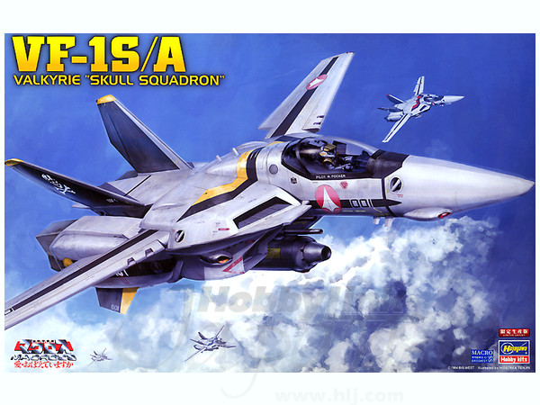
VF-1 Valkyrie Background:
The VF-1 Valkyrie is a fictional aircraft mecha from the 1980s animated series “Robotech” from Harmony Gold USA/Tatsunoko. The series is a treat to watch but a better read with the Jack McKinney novelizations. The premise is that unique alien technology crash lands on Earth and after humans attempt to repurpose it, the Earth is attacked by a new group of aliens after the crashed ship and its powerful technology. The technology revolves around a new energy source called “protoculture” that enabled the development of advanced robotics and technology on Earth. The fighter aircraft on Earth use “Robotechnology” that uses energy source and enables the aircraft to perform complex transformations for different purposes.
Veritech (Variable) Fighter [VF]:
The VF-1 Valkyrie is the first “mass-produced” veritech fighter aircraft to use the advanced technology and has three unique configuration modes. The FIGHTER, GERWALK and BATTLOID modes each provide unique advantages in combat. Transforming into each mode is a complex ballet of moving components but can be done at extreme speeds thanks to the advanced technology found on the crashed alien ship.
FIGHTER (Mode F):
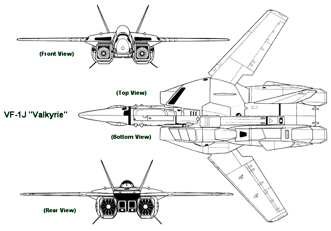
The FIGHTER mode is the standard mode that looks very similar to any basic aircraft. The VF-1 in particular is a twin engine variable sweep aircraft based off of the F-14 Tomcat with a tail similar to the F-18 Hornet. Vectoring thrust from the two engine pods as well as Vernier thrusters on the wings and nose provide maximum maneuverability in and out of atmospheric environments.
GERWALK (Mode G):
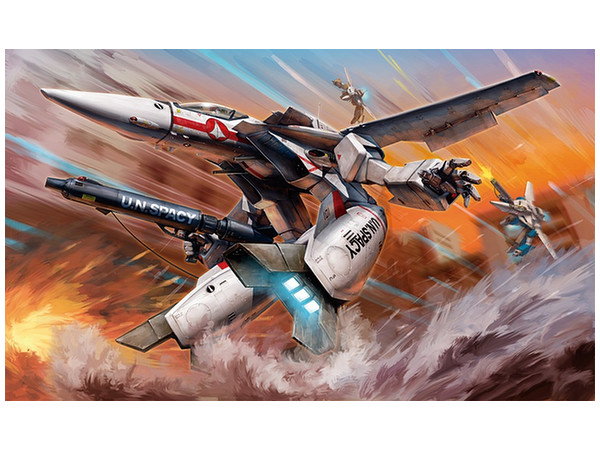
This mode is the mixture of both the FIGHTER and BATTLOID modes. The aircraft drops the engine pods below the fuselage and forward facing. The pods act as legs similar to an ostrich with the nozzles being the feet. Arms that were hidden underneath the now folded tail between the engine pods, swing out and help balance the half robot, half aircraft system. In this mode, the vehicle can walk or hover above the ground, taking advantage of ground effect when moving. Larger Vernier thrusters revealed when the tail folds up are used to support balance and forward propulsion in this mode. The F and G modes are the ultimate goals for this RC design.
BATTLOID (Mode B):
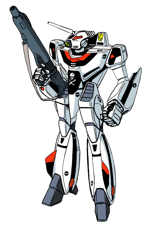
Although not planned for this design, the BATTLOID mode is the full bi-pedal robot configuration. The wings swing all the way back under the folded tail and thruster pack that looks like a jet pack. The legs are swung further forward, and the hip joints attach to sockets in the nose. The cockpit slides up behind a shield and the vehicle folds in half revealing the robot head that spins forward. The arms slide to the sides and the final result is a humanoid robot.
Goals:
FIGHTER Mode
1) It can fly
2) Variable wing geometry
3) Vectoring Thrust
4) >1.5:1 TWR
5) It can fly
GERALK Mode
1) It can support itself on the ground
2) It can hover
3) It can transform while on the ground from G to F and the reverse
4) It can fly in mode G
5) It can transition from G to F and the reverse while flying
Current Design Steps:
Weight: <6lbs (2.7kg)
Thrust (Total): 12lbs (5.3kg)
EDF Size: 70-80mm
Flight Time: >1min
Controls/Actuation Breakdown:
Wing Sweep: 1 micro servo with the right linkage should be able to actuate the wings.
Aileron: The VF-1 does have aileron surfaces, however, I will not be including them initially as to simplify the setup and keep the weight low.
Elevator: Most pitch control comes from thrust vectoring, however there is a large flap behind the tail section on the VF-1 that acts as an elevator of sorts. I think for the initial design I may not include it to simplify the setup and keep the weight low.
Rudder: The twin tails of the VF-1 are only there for stability in my opinion. I will need to do a bit of research to verify so yaw will be controlled using differential thrust.
Nozzles (Feet): The 1D vectoring nozzles on the VF-1 are split top and bottom so they can be spread for use as feet in the G and B modes. Otherwise they work together to vector thrust in the vertical dimension only. For my design, each engine pod will have two linear servos that control each nozzle half separately.
Engine Pod (Hip): The hip in the G mode is complex. It has to lower the knees below the aircraft belly as well as rotate to provide the engine pod dihedral from the aircraft centerline. I plan to bind both hips at the initial joint a drive them with a single servo. Then separate servos will rotate at hip joint to provide the dihedral angles for each leg. This will be the hardest to implement and still be structurally sound and light.
Engine Pod (Knee): A single servo for each knee should be sufficient to provide the range of motion needed.
Pitch Control: In mode F, I should have full control with my TX with the elevator channel controlling the knee joint a specific range of angles. In mode G, I will still have the same control but works with a microcontroller or gyro tasked with maintaining the vehicle as level as possible.
Roll Control: In mode F, I should have full control with my TX with the aileron channel controlling the nozzle angles. In mode G, control will be primarily from a microcontroller or gyro tasked with maintaining the vehicle as level as possible. If I want to “roll” the vehicle in mode G, the rudder channel will need to be used which controls the thrust levels in each engine pod.
Yaw Control: In mode F, I should have full control with my TX with the rudder channel controlling the differential of the two engines. An alternative differential control that was suggested is to add a clamshell thrust level system in each leg that would also use the rudder channel. In mode G, I control yaw with the aileron channel which works with a microcontroller or gyro tasked with maintaining the vehicle as level as possible.
Tail Fold (Mode G): Folding the tail over may be possible mechanically by tying it to the hip drop servo.
Tail Vernier Thruster: It may be possible to add a micro EDF to the tail that can support balance and directional control while in mode G. Not a primary objective though.
Arms: Although they may assist with balance, I will not be planning on implementing them at this scale unless someone thinks they have a great idea for implementing efficiently.
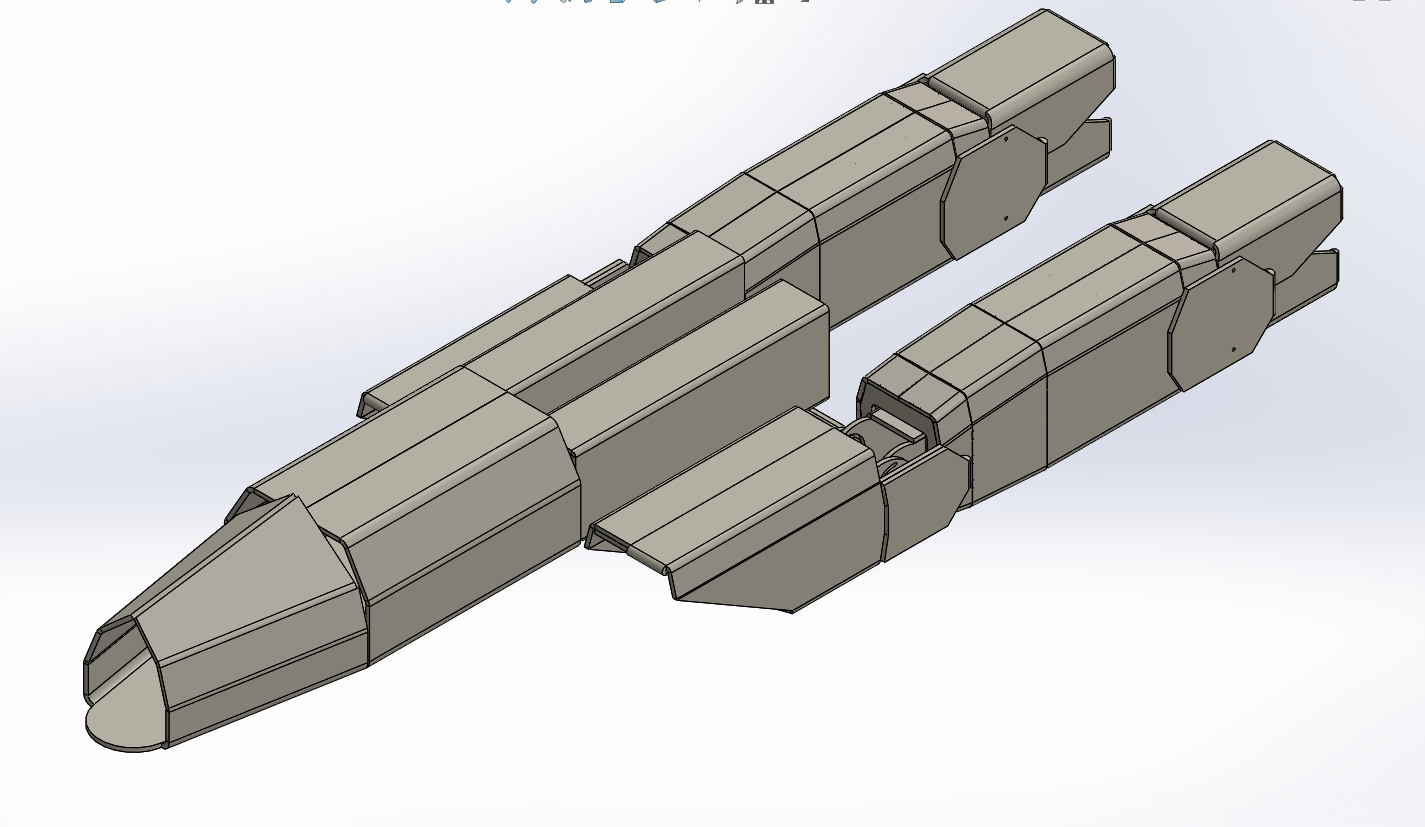
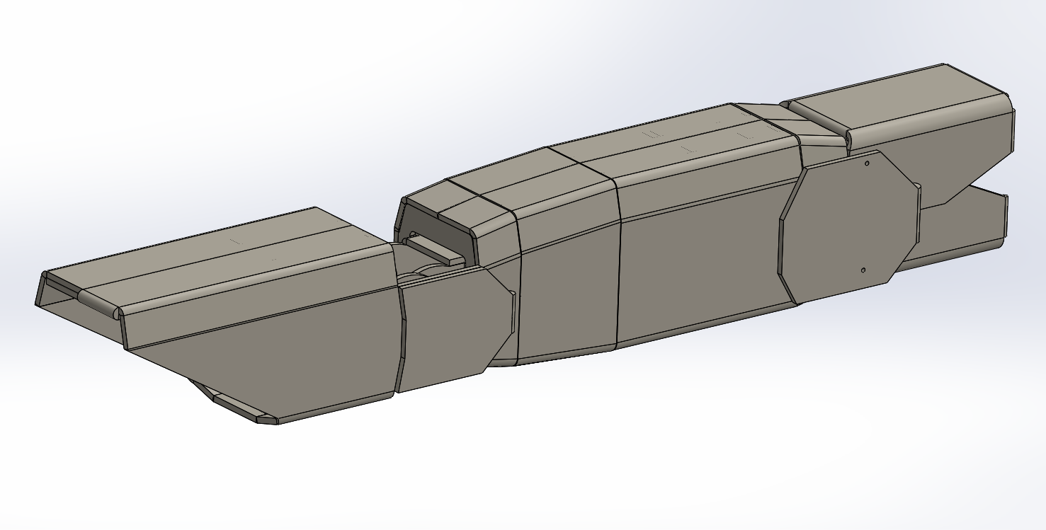
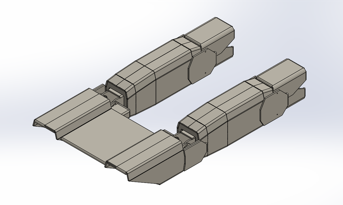
Current Design Progress: Leg Section 90% Complete. Re did the proportions of the leg. Initial core design, nose sections will probably be done by hand so it would be smoother than shown. The bends are really just place holders. The wing core, tail element, and the wings themselves are all that's left to work on. So far the model is looking to be 3.2lbs without glue/hardware, the ESCs, batteries, RX, hip servos (<3), sweep servo and the gyro/sensor/processor. I think being under 6lbs is plausible depending on the battery setup. The CG right now is just above the knee lined up with the forward bulkhead of the calf section, close to where I want it to be for right now.
This thread will keep track of my progress as I try to design and build an aircraft based on the VF-1A Valkyrie and two of its specialized modes, the FIGHTER and GERWALK. I have been wanting to try this for years and decided to bite the bullet and put some legit effort into making this happen. Initially I will be aiming for EDF with controls being shared between a 6-channel TX and an on-board microprocessor for active stability assist when in and transforming into/from the GERWALK mode. First goal is to get a flyable system after testing the engine pod design. Then implementing a microprocessor or gyro setup to help with stability will lead into the GERWALK mode testing. Enjoy and any tips, tricks, opinions, ideas are more than welcome!

VF-1 Valkyrie Background:
The VF-1 Valkyrie is a fictional aircraft mecha from the 1980s animated series “Robotech” from Harmony Gold USA/Tatsunoko. The series is a treat to watch but a better read with the Jack McKinney novelizations. The premise is that unique alien technology crash lands on Earth and after humans attempt to repurpose it, the Earth is attacked by a new group of aliens after the crashed ship and its powerful technology. The technology revolves around a new energy source called “protoculture” that enabled the development of advanced robotics and technology on Earth. The fighter aircraft on Earth use “Robotechnology” that uses energy source and enables the aircraft to perform complex transformations for different purposes.
Veritech (Variable) Fighter [VF]:
The VF-1 Valkyrie is the first “mass-produced” veritech fighter aircraft to use the advanced technology and has three unique configuration modes. The FIGHTER, GERWALK and BATTLOID modes each provide unique advantages in combat. Transforming into each mode is a complex ballet of moving components but can be done at extreme speeds thanks to the advanced technology found on the crashed alien ship.
FIGHTER (Mode F):
The FIGHTER mode is the standard mode that looks very similar to any basic aircraft. The VF-1 in particular is a twin engine variable sweep aircraft based off of the F-14 Tomcat with a tail similar to the F-18 Hornet. Vectoring thrust from the two engine pods as well as Vernier thrusters on the wings and nose provide maximum maneuverability in and out of atmospheric environments.

GERWALK (Mode G):
This mode is the mixture of both the FIGHTER and BATTLOID modes. The aircraft drops the engine pods below the fuselage and forward facing. The pods act as legs similar to an ostrich with the nozzles being the feet. Arms that were hidden underneath the now folded tail between the engine pods, swing out and help balance the half robot, half aircraft system. In this mode, the vehicle can walk or hover above the ground, taking advantage of ground effect when moving. Larger Vernier thrusters revealed when the tail folds up are used to support balance and forward propulsion in this mode. The F and G modes are the ultimate goals for this RC design.

BATTLOID (Mode B):
Although not planned for this design, the BATTLOID mode is the full bi-pedal robot configuration. The wings swing all the way back under the folded tail and thruster pack that looks like a jet pack. The legs are swung further forward, and the hip joints attach to sockets in the nose. The cockpit slides up behind a shield and the vehicle folds in half revealing the robot head that spins forward. The arms slide to the sides and the final result is a humanoid robot.

Goals:
FIGHTER Mode
1) It can fly
2) Variable wing geometry
3) Vectoring Thrust
4) >1.5:1 TWR
5) It can fly
GERALK Mode
1) It can support itself on the ground
2) It can hover
3) It can transform while on the ground from G to F and the reverse
4) It can fly in mode G
5) It can transition from G to F and the reverse while flying
Current Design Steps:
- Complete performance envelope calculations for stability and feasibility
- Develop/procure Bill of Materials (BOM) that meets envelope requirements
- Develop EDF Engine Pod Test Bed (Foam Board/Wood)
- Develop Control Board/Software Program for stability and control drivers
- Develop EDF Flight Test Model (Foam Board/Wood)
- Maiden Flight FTM in mode F
- Validate and improve performance in mode F
- Maiden Flight FTM in mode G
- Validate and improve stability in mode G
- Test transition from mode G to F and F to G on the ground/air
- Improve transition time with software/hardware improvements
- Push the structure limits by transforming while under forward motion from mode F to G at higher and higher speeds.
- Investigate potential for scaling vehicle smaller or larger with goal of jet engine variant
Weight: <6lbs (2.7kg)
Thrust (Total): 12lbs (5.3kg)
EDF Size: 70-80mm
Flight Time: >1min
Controls/Actuation Breakdown:
Wing Sweep: 1 micro servo with the right linkage should be able to actuate the wings.
Aileron: The VF-1 does have aileron surfaces, however, I will not be including them initially as to simplify the setup and keep the weight low.
Elevator: Most pitch control comes from thrust vectoring, however there is a large flap behind the tail section on the VF-1 that acts as an elevator of sorts. I think for the initial design I may not include it to simplify the setup and keep the weight low.
Rudder: The twin tails of the VF-1 are only there for stability in my opinion. I will need to do a bit of research to verify so yaw will be controlled using differential thrust.
Nozzles (Feet): The 1D vectoring nozzles on the VF-1 are split top and bottom so they can be spread for use as feet in the G and B modes. Otherwise they work together to vector thrust in the vertical dimension only. For my design, each engine pod will have two linear servos that control each nozzle half separately.
Engine Pod (Hip): The hip in the G mode is complex. It has to lower the knees below the aircraft belly as well as rotate to provide the engine pod dihedral from the aircraft centerline. I plan to bind both hips at the initial joint a drive them with a single servo. Then separate servos will rotate at hip joint to provide the dihedral angles for each leg. This will be the hardest to implement and still be structurally sound and light.
Engine Pod (Knee): A single servo for each knee should be sufficient to provide the range of motion needed.
Pitch Control: In mode F, I should have full control with my TX with the elevator channel controlling the knee joint a specific range of angles. In mode G, I will still have the same control but works with a microcontroller or gyro tasked with maintaining the vehicle as level as possible.
Roll Control: In mode F, I should have full control with my TX with the aileron channel controlling the nozzle angles. In mode G, control will be primarily from a microcontroller or gyro tasked with maintaining the vehicle as level as possible. If I want to “roll” the vehicle in mode G, the rudder channel will need to be used which controls the thrust levels in each engine pod.
Yaw Control: In mode F, I should have full control with my TX with the rudder channel controlling the differential of the two engines. An alternative differential control that was suggested is to add a clamshell thrust level system in each leg that would also use the rudder channel. In mode G, I control yaw with the aileron channel which works with a microcontroller or gyro tasked with maintaining the vehicle as level as possible.
Tail Fold (Mode G): Folding the tail over may be possible mechanically by tying it to the hip drop servo.
Tail Vernier Thruster: It may be possible to add a micro EDF to the tail that can support balance and directional control while in mode G. Not a primary objective though.
Arms: Although they may assist with balance, I will not be planning on implementing them at this scale unless someone thinks they have a great idea for implementing efficiently.
Current Design Progress: Leg Section 90% Complete. Re did the proportions of the leg. Initial core design, nose sections will probably be done by hand so it would be smoother than shown. The bends are really just place holders. The wing core, tail element, and the wings themselves are all that's left to work on. So far the model is looking to be 3.2lbs without glue/hardware, the ESCs, batteries, RX, hip servos (<3), sweep servo and the gyro/sensor/processor. I think being under 6lbs is plausible depending on the battery setup. The CG right now is just above the knee lined up with the forward bulkhead of the calf section, close to where I want it to be for right now.


Attachments
Last edited:


