Willy Nilles "Jr. Skylark 250" Beta Kit Build and Flight

TooJung2Die

Master member
I'm a big fan of delayed gratification so I'm starting to build the Jr. Skylark 250 kit I got last winter. Everyone else says I'm a procrastinator. 🙂 Since this is a Beta kit I'll point out some things I think should be fixed. Not because I like to complain but it's a Beta kit and Doug did ask for constructive criticism. Here are the kit contents.
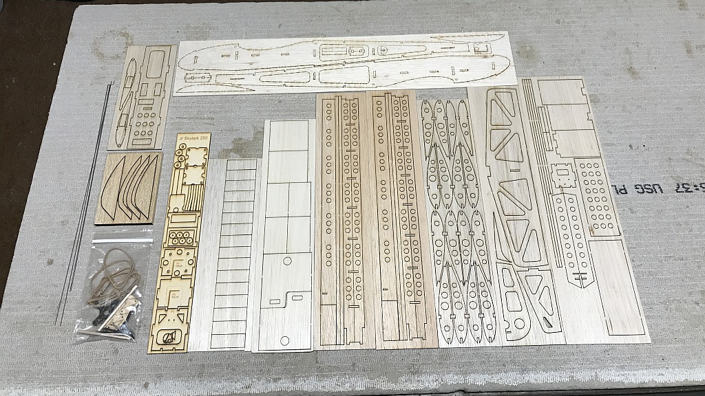
IMG_2339crop.jpg


I'll start with the fuselage. I've sorted out everything I think I'll need to build the fuselage for electric motor. I probably won't use the balsa canopy so I didn't separate those pieces.

IMG_2341crop.jpg


I noticed right away the little triangular piece that goes on the bottom of the tip of the tail is missing. Search the first photo and you won't find it. It's supposed to be here:
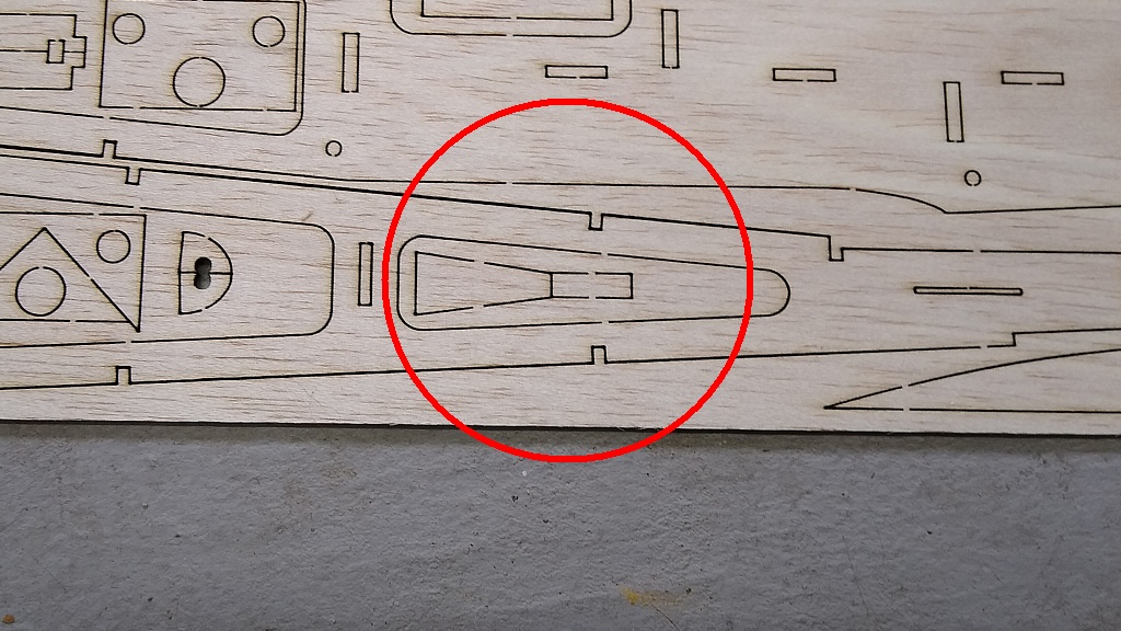
Missing pieces.jpg


No problem, I'll make one from scrap later. I know from building the Eaglet 250 the first step is making the landing gear from 0.055" wire included in the kit. There is supposed to be enough wire to make the elevator joiner too but when I was done there was only about 1" of wire left. Again, no problem, I have lots of piano wire.

IMG_2350crop.jpg


When I dry fit the fuselage bulkheads and servo/battery tray I found I couldn't put the firewall with landing gear in place. I think there should be a cut-out here. That's a real easy fix.

IMG_2342 cut out missing.jpg


There is one short shear web in the sheet. Same thing I found with the Eaglet 250 Beta kit. All the shear webs are 0.625" in height except for this one that is only 0.585".

IMG_2352crop.jpg


That's all I got done tonight. If I had to find something serious to complain about it would be that Willy Nillies kits are too easy and build too fast. This gonna be fun! 😁😁😁

Jon
 
Last edited:

TooJung2Die

Master member
I didn't get much time to work on the Skylark but this kit won't take long to build. The servo/battery tray, firewall and main bulkheads are glued in place. I'll be using thin CA for 99% of the assembly.

IMG_2355crop.jpg


The formers are glued in with the vertical braces shown by the arrow. The vertical braces keep the balsa from bending when the covering film shrinks over the large openings in the fuselage.

IMG_2356crop.jpg


The fuselage stringers are next. This photo shows the top side. The small cross piece at the rear end of the stringers was made from scrap balsa. It is another little piece that was missing from the laser cut.

IMG_2357crop.jpg


Bottom fuselage stringers. The arrows show the missing triangular piece made from scrap balsa and a small cross piece I decided to add instead of running the stringers all the way back.

IMG_2358crop.jpg


After playing around with these pieces and looking at other build threads I figured out where these three pieces belong. The top two are the fuselage top sheeting (or hatches, depending on how you build) and the bottom piece is the sheeting for the bottom of the nose.

IMG_2359crop.jpg


Dry fit of the fuselage top sheeting.

IMG_2361crop.jpg


I have these two pieces left over. I figured out the swiss-cheese-looking piece glues to the inside of the top center hatch to align it with the fuselage sides (I have a different idea). The other piece of balsa, as far as I can tell, is not used on this fuselage. Let me know if it has a purpose I don't know about.

IMG_2360crop.jpg


It took very little time to get the fuselage mostly assembled. When you don't have to do any measuring and sanding to fit everything the build goes incredibly quick. Using CA glue speeds it up too.

Jon.
 
Last edited:

TooJung2Die

Master member
The bottom nose sheeting is wet and held to the fuselage to dry. It looks like the sheet is 7/32" too short. This has to be the right piece because it is the only piece that has the cutout for the front landing gear wire.

IMG_2362crop.jpg


Is it like this in other Skylark kits? I can either glue on an extension or modify the extra piece of fuselage sheeting to fit. I remember that extra piece from the Eaglet build. It goes on the bottom around the main landing gear. Did I get the laser cut sheet for the wrong airplane?

Jon
 

speedbirdted

Legendary member
Good idea using popsicle sticks to prevent leaving holes in things. Though, why perma-bend it? If you use some sort of latch, the little amount of mechanical pressure generated by bending the wood will help keep it closed. Or is that not a hatch, and just goes in permanently?

I remember my Eaglet had a similar problem but it was less severe since the bottom piece doesn't actually come up to the wing, as it isn't there. It also didn't have a cutout for the nosewheel wire. In any case I ended up just making my own hatch as it needed to be a significantly different shape anyhow...
 

TooJung2Die

Master member
It is going to be a semi-permanent hatch held closed with a tiny screw. The ESC will be under this hatch so it won't be opened unless there is a problem. After bending the hatch I used the left-over fuselage cutout curve to make formers so it'll hold it's shape. I will have to add an extension to the hatch so it is the correct size.

I understand why you are suggesting it be left flat. I enjoy bending and shaping wood. After covering it will probably flatten out a bit.

IMG_2363crop.jpg


Jon
 
Last edited:

Willy Nillies

Elite member
The bottom nose sheeting is wet and held to the fuselage to dry. It looks like the sheet is 7/32" too short. This has to be the right piece because it is the only piece that has the cutout for the front landing gear wire.

View attachment 177784

Is it like this in other Skylark kits? I can either glue on an extension or modify the extra piece of fuselage sheeting to fit. I remember that extra piece from the Eaglet build. It goes on the bottom around the main landing gear. Did I get the laser cut sheet for the wrong airplane?

Jon

Hi John,

Look like you got the cut sheet for the Jr. Falcon instead of the Jr. Skylark..... The other rectangular piece you show in the pic with the hatch doubler would have been glued to the aft edge of the one in the pic above. We can send you the correct parts if you like.

Sincerely,
Doug and Becky
WillyNillies.com
 

TooJung2Die

Master member
Hi Dug,

Thank you for the generous offer. It is not a problem. I am happy you are aware that it happened. I hope you don't find many other kits like this.

Jon
 

speedbirdted

Legendary member
Do the servos go in upside down? It seems like the middle piece thingy that they get glued/screwed into is too low to let them go in right side up without interfering with the wing. Most low wingers I've seen have the rudder/elevator servos in upside down anyway to make it easier to get to the horns and control linkages with the wing off.
 

TooJung2Die

Master member
Do the servos go in upside down?
Doug wrote in a RCGroups thread that the Jr. Skylark servos are supposed to go in upside down under the tray. I tried fitting the fuselage pieces so the servos would mount upside down. It doesn't work that way. Nothing fit or lined up right.

When I dry fit the bulkheads with the push rod holes on the bottom the bulkheads didn't fit the fuselage sides. The push rod holes didn't line up with the slots in the tail. When I flipped the bulkheads over with the push rod guide holes on top the bulkheads fit the fuselage sides and the push rod holes lined up perfectly with the slots. The push rod holes also line up perfectly with the servo arms with the servos on top. It's just like the Eaglet in this regard. Everything fits and lines up great with the servos on top.

The servos don't attach directly to the servo tray. You are supposed to use the plywood servo rails that are included in the kit. The rails position the servos high enough so they don't contact the wing.

Maybe I got more pieces mixed in from a different airplane in this kit? :unsure: Nope, the plywood bulkhead sheet is clearly marked "Jr Skylark 250".
 
Last edited:

TooJung2Die

Master member
I think I now know why things didn't line up when I tried to assemble the fuselage with the servos mounted upside down under the servo tray. The last bulkhead, rearmost position, is from the Jr. Falcon laser cut sheet! That's the bulkhead that didn't fit the fuselage sides when installed with the push rod holes towards the bottom. I think everything will be fine with the servos mounted on top of the servo tray.

IMG_2339cropresize.jpg


Jon
 

Willy Nillies

Elite member
Boy we really messed this one up for you! Falcon and Skylark are close, but not exactly the same as you've found out!

The error's in your firsts post were corrected long ago. PLEASE send us an email..... we'll make good on this error!

Sincerely,
Doug and Becky
WillyNillies.com
 

TooJung2Die

Master member
I discovered some other parts on the sheet that was supposed to be in this kit. I don't have the parts to complete the landing gear for the wing. Doug is keeping his word and sending the missing sheet to complete the wing. If you find any issues with your Willy Nillies kits call their phone. Doug has answered every time I called. He's a great guy and you'll learn a lot from talking to him.
 

TooJung2Die

Master member
I took a lot of photos of the wing build up to this point but I'm skipping them because this wing is the same as the Eaglet and many other Willy Nillies kits.


IMG_2389 crop.jpg


The hole plugs in the leading edge are glued in to make it solid. I'm not going to use the shear webs. This wing is already very strong and will be even stronger after covering. I made the holes in the top sheeting for the servo leads. Next step for the wing is mounting the landing gear wire.

Jon
 
Last edited:

TooJung2Die

Master member
It has been over two weeks since I talked to Doug and he said he was sending the missing balsa sheet. I went on vacation and expected it to be waiting for me when I returned. Maybe Doug is on vacation too. I used the full size template from the landing gear wire drawings to cut the missing landing gear parts by hand. Leave the outside dimensions a little large so you can sand them down to match the main ribs after the glue sets. 30 minute epoxy gets used here for filling the gaps and good adhesion. Wire and supports glued and clamped:

IMG_2426crop.jpg


Sanded to match the ribs.

IMG_2427crop.jpg


I am going to use shear webbing on either side of the ribs that mount the landing gear. Gawd knows my landing gear needs all the reinforcement it can get. 😆

Jon