LennyPane
zenFPV
Y3 Tri-Copter - with Tail Yaw Mechanism - |Build Log|
Hey Guys,
i'm new here, and starting to plan my first build with a tricopter design. love the flite test videos, very good to get to grips with everything!
i will document my steps along the way, maybe it'll be helpful to somebody.
my plan is: i want it to be relatively cheap (around 250EUR/270$), but still be accurate and have the capacity to race or start to learn aerobatics once i know how to fly.
i already did a lot of research, got confused, then less confused, then more confused(mainly about motor, prop and battery sizes)
i'm just wondering if my plans and parts will cooperate and fit together. but im looking forward to building, fiddling and figuring it all out as i go.
PART I
15.1.2015
thinking ahead:
Tail Yaw Mechanism
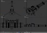
the 10x10mm tail arm is inserted into two 10mmØ ball bearings, rotating the whole back arm assembly, instead of just the motor. fastening the arm and ball bearings into the stiffened tail end of the main frame, hopefully making it really robust, but also freely tilt-able with next to no resistance.
and not only that, but with this configuration i can put the yaw servo right in the middle of the copter, behind the arm inside the main frame, thus keeping all the parts in the middle and the center of gravity focused.
Center of Gravity
i will also try and mount the motors on the ends of the arms as well as 'bend' the arms down if i manage to get that done. all that to keep the center of gravity (height wise) right in the middle.
(instead of the main frame 'dangling' under the motors like a shallow pendulum... but.. i guess moving the arms and motors down like this will actually bring the CG below the main frame because the force is transmitted at the bottom of the motor where it is fastened to the arm, right?.. hmm not so good. although with the battery pack its probably spot on )
i also thought, maybe i can even mount the ESC's around the tail-ball bearing mechanism(white boxes, red cables - as pictured) and feed the motor wires through the hollow arms. keepin' it tidy
there's also a slot in the top plate under the KK1.2.5 board to feed cables through.
Planned Parts/Specs:
KK2.1.5 + 19S firmware
EMAX CF2822 1200Kv
ESC Simonk 30A
EMAX ES08MD 12g/ 2.4kg/ .08 sec
3000MAh Fleureon 30C, 11,1v
9x5 or 10x4.5 Props
Flysky FS-T6-RB6 FS 2.4GHz
maybe fpv; SKY2 800TVL (flat spot on the main frame front for camera)
Updated Parts:
Carbon Plate 40cm x 20cm
Carbon hollow Tube ø12mm x 1m
2x Ball Bearring ø12mm x 24mm x 6mm
MWC Multiwii SE 3.0
FlySky FS-T6 V2 + RB6
Sunnysky x2212-10, 1250Kv
Corona DS-319MG Servo
ESC Simonk 30A
Turnigy Nano-Tech 3200mAh 25-50C
Turnigy Nano-Tech 2500mAh 5-10C (Tx Battery)
9x4.7“ SlowFlyer Prop
Materials:
carbon arms, carbon frame plates, plastic frame fillers
Sketches: (made with blender)


tail yaw mechanism and ESC to Motor cables

folded arms

inside main frame without servo - ball bearing yaw mechanism, ESC to motor cables
__________________________________________________ _______


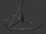
Planned Dimensions:

everything is not fixed yet, don't know if 3D dimensions correspond to the real world...
all the bought parts(esc's, KK2.1.5, motors etc.) have the correct proportions in these sketches though
thats about it, i'll keep updating this if i can as i go along.
if you have suggestions, critique, ideas, words, unicorns feel free to share.
cheers,
Lenny

Hey Guys,
i'm new here, and starting to plan my first build with a tricopter design. love the flite test videos, very good to get to grips with everything!
i will document my steps along the way, maybe it'll be helpful to somebody.
my plan is: i want it to be relatively cheap (around 250EUR/270$), but still be accurate and have the capacity to race or start to learn aerobatics once i know how to fly.
i already did a lot of research, got confused, then less confused, then more confused(mainly about motor, prop and battery sizes)
i'm just wondering if my plans and parts will cooperate and fit together. but im looking forward to building, fiddling and figuring it all out as i go.
PART I
15.1.2015
thinking ahead:
Tail Yaw Mechanism
the 10x10mm tail arm is inserted into two 10mmØ ball bearings, rotating the whole back arm assembly, instead of just the motor. fastening the arm and ball bearings into the stiffened tail end of the main frame, hopefully making it really robust, but also freely tilt-able with next to no resistance.
and not only that, but with this configuration i can put the yaw servo right in the middle of the copter, behind the arm inside the main frame, thus keeping all the parts in the middle and the center of gravity focused.
Center of Gravity
i will also try and mount the motors on the ends of the arms as well as 'bend' the arms down if i manage to get that done. all that to keep the center of gravity (height wise) right in the middle.
(instead of the main frame 'dangling' under the motors like a shallow pendulum... but.. i guess moving the arms and motors down like this will actually bring the CG below the main frame because the force is transmitted at the bottom of the motor where it is fastened to the arm, right?.. hmm not so good. although with the battery pack its probably spot on )
i also thought, maybe i can even mount the ESC's around the tail-ball bearing mechanism(white boxes, red cables - as pictured) and feed the motor wires through the hollow arms. keepin' it tidy
there's also a slot in the top plate under the KK1.2.5 board to feed cables through.
Planned Parts/Specs:
KK2.1.5 + 19S firmware
EMAX CF2822 1200Kv
ESC Simonk 30A
EMAX ES08MD 12g/ 2.4kg/ .08 sec
3000MAh Fleureon 30C, 11,1v
9x5 or 10x4.5 Props
Flysky FS-T6-RB6 FS 2.4GHz
maybe fpv; SKY2 800TVL (flat spot on the main frame front for camera)
Updated Parts:
Carbon Plate 40cm x 20cm
Carbon hollow Tube ø12mm x 1m
2x Ball Bearring ø12mm x 24mm x 6mm
MWC Multiwii SE 3.0
FlySky FS-T6 V2 + RB6
Sunnysky x2212-10, 1250Kv
Corona DS-319MG Servo
ESC Simonk 30A
Turnigy Nano-Tech 3200mAh 25-50C
Turnigy Nano-Tech 2500mAh 5-10C (Tx Battery)
9x4.7“ SlowFlyer Prop
Materials:
carbon arms, carbon frame plates, plastic frame fillers
Sketches: (made with blender)


tail yaw mechanism and ESC to Motor cables

folded arms

inside main frame without servo - ball bearing yaw mechanism, ESC to motor cables
__________________________________________________ _______


Planned Dimensions:

everything is not fixed yet, don't know if 3D dimensions correspond to the real world...
all the bought parts(esc's, KK2.1.5, motors etc.) have the correct proportions in these sketches though
thats about it, i'll keep updating this if i can as i go along.
if you have suggestions, critique, ideas, words, unicorns feel free to share.
cheers,
Lenny
Last edited:


