1 Sheet Plane

Mad_Mechanic

Well-known member
So I was thinking about the box spar that @BATTLEAXE made and I had an idea, let me know what you all think about this for a revised spar.

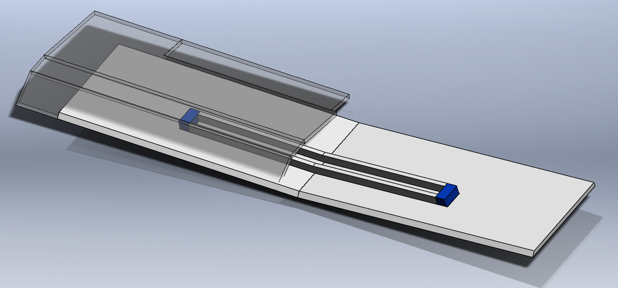
Instead of the C-fold spar, what if the wing used a "beam spar," hopefully I can explain this and why this might have some advantages.

I played around in SolidWorks and came up with this concept.
Beam Spar Wing.PNG


The idea here is that it would utilize the on-edge strength of foam board and at the same time it would be two pieces cut identical that include the dihedral angle in the piece. This (in theory) would simplify forming the wing. You can also run wires between the beams like a box spar.

Thoughts?

Post Edit: In terms of potential weight savings in foam board here is what it could look like. (without accounting for glue)

Version 1 C-fold spar: ~3.7 grams

Version 2 proposed Beam Spars: 2 spars at ~.9 grams each, ~1.8g total
 

Mad_Mechanic

Well-known member
Sorry for the post spam, wanted to give an overall update on potential foamboard weight savings based on the proposed changes. Weights reported are airframe only (no electronics) and do not account for glue and tape.

Prototype V1 airframe weight: 86.4 grams

Prototype V2 airframe weight: 81.0 grams

total weight savings so far ~5.4 grams or almost 1 entire micro servo.
 

BATTLEAXE

Legendary member
Is this what you are thinking? This is with 2-in (~50mm) removed from both sides of the lower wing panels.

*There is no science to the 2-in here at the moment

View attachment 139329

Weight savings as shown is as follows (calculated via solidworks and does not account for weight of glue)

Version 1 prototype wing design: ~66.5 grams

Version 2 prototype proposal (shown) wing design: ~63.2 grams

Theoretical weight savings: 3.3 grams

That sounds fairly negligible, but when you figure that my plan calls for 4x servos that weigh ~6g a piece, that 3.3 grams is about half a servo in weight. It does all add up.
This is what i was thinking for the wing. Thank you for considering the changes. Even upon further inspection if you wanted to take it to an extreme you could look at, just for experimental sake, and its all on CAD so no harm no foul, that if you even doubled the amount to 4", just to the outer tip of the aileron, was removed. That would leave you with just under 1/3rd of the wing span as an under camber, (given each wing span minus half the width of the fuse from center is 12.5"), thus being a 6.6 grams in weight savings. And still gives plenty of support to the servos in the wing.
@CapnBry @BATTLEAXE - Here is where I'm at on fuselage changes.

For reference, here is the flat pattern for the initial prototype design release.

View attachment 139341

For prototype version 2 (work in progress) I've changed the wing cutout as per what BATTLEAXE suggested. This was an idea that I had considered during the initial prototype design but abandoned it thinking it would add more cuts and reduce fuselage strength. However, thinking about it again, it does reduce a little weight and once you glue the wing in place, you will gain back any lost fuselage strength.

I also added tabs at the back where the elevator mounts which will correspond with slots to be cut into the elevator. This should also help the fuselage hold it's shape, add some strength and does not add additional weight (the weight added to the fuselage is removed from the elevator, thus net-zero).

View attachment 139342

Lastly, I went ahead and added some length to the nose section as-per CapnBry's suggestion. I maintained the distance from the tail end of the fuselage to the front of the wing (also as per CapnBry). The amount added is ~5/8-in (~16mm). Here is the v1 compared to v2 so you can see the length difference.

View attachment 139343

As shown, the fuselage weight (without glue) is as follows:

Version 1 Prototype: 20.7 grams

Version 2 (WIP) Prototype: 20.2 grams

Not much weight savings on it's own (~0.5g), but as I said in the wing modification post, it all adds up.
I know you wouldn't save much weight here in the wing allowance cut out especially if you added 16mm of material on 4 panels to cover the nose extension. Actually... looking at it more closely, and i could be wrong here, but if you added to the nose length shouldn't the spar placement be the same in both V1 and V2. As it sits it looks like you extended the moment between the wing and the tail. Which creates more stability in flight, not arguing that it's a bad thing but was that what CapnBry was talking about?

It would be interesting if these changes would allow you to shuffle things around on the sheet, and how much surface area on the sheet it actually takes up.

Side note... since i am using a 3s 850 in this plane with the F Pack powertrain and my aileron servo location, (mind you the spar would have been in the way as well), I have had to do some custom fitting in the hatch to place the battery. Pro- The battery is placed over the intended CG so it will balance well with any battery size. Con- had to deviate on the hatch design some and hack a hole in it to fit the battery into the fuse dimensions, (might get to make a canopy for it after all). Almost done, just installing the Rx and it's maiden time, weather permitting of coarse.
 

Mad_Mechanic

Well-known member
I know you wouldn't save much weight here in the wing allowance cut out especially if you added 16mm of material on 4 panels to cover the nose extension. Actually... looking at it more closely, and i could be wrong here, but if you added to the nose length shouldn't the spar placement be the same in both V1 and V2. As it sits it looks like you extended the moment between the wing and the tail. Which creates more stability in flight, not arguing that it's a bad thing but was that what CapnBry was talking about?

Good questions, I recall asking CapnBry about the nose thing when he first suggested. I suggested moving the wing back towards the tail instead of actually adding length to the fuselage as this would effectively give you more nose length compared to wing placement. He advised against this and suggested keeping the wing where it was in relation to the tail.

However, that being said, I see the issue you are pointing out, I didn't actually move the spar cutout location on the flat pattern. This is an oversight on my part as I have two working files in SolidWorks: a signel piece "formed" fuselage I use for making assemblies with and another Flat Pattern file I use for the foamboard layouts. any change I make to one I have to remember to make to the other. I missed this when I made the fuselage flat pattern longer, I will go fix this right now.

Good catch!
 

Mad_Mechanic

Well-known member
Found my error in the flat pattern, thanks again @BATTLEAXE for spotting that issue and bringing it to my attention.

The spar clearance cut probably still doesn't look like it lines up exactly but I'm adjusting the cutout there for some clearance on the spar to account for potential variance in how people build their wings. With the larger body cutout to recess the wing, I'd rather have the leading and trailing edges of the center of the wing do the 'indexing' to locate the wing.

fuselage compare fixed.PNG
 

BATTLEAXE

Legendary member
Good questions, I recall asking CapnBry about the nose thing when he first suggested. I suggested moving the wing back towards the tail instead of actually adding length to the fuselage as this would effectively give you more nose length compared to wing placement. He advised against this and suggested keeping the wing where it was in relation to the tail.

However, that being said, I see the issue you are pointing out, I didn't actually move the spar cutout location on the flat pattern. This is an oversight on my part as I have two working files in SolidWorks: a signel piece "formed" fuselage I use for making assemblies with and another Flat Pattern file I use for the foamboard layouts. any change I make to one I have to remember to make to the other. I missed this when I made the fuselage flat pattern longer, I will go fix this right now.

Good catch!
I like the changes you made to the spar as well. Got a decent amount of weight out of that one comparatively huh. Sweet deal. What do you think about the wing tip under camber thing i was talking about? Given all these changes what would be the total weight savings from V1 to V2?

This is fun, it's cool to collaborate, get to fill in any holes and discrepancies to design a cleaner more efficient product.
 

Mad_Mechanic

Well-known member
I like the changes you made to the spar as well. Got a decent amount of weight out of that one comparatively huh. Sweet deal. What do you think about the wing tip under camber thing i was talking about? Given all these changes what would be the total weight savings from V1 to V2?

Haven't forgotten about your wing tip under camber idea (removing yet more material) just haven't gone back around to looking at the wing again.

The only thing I can think of to 'argue against' taking out more material at this time would be to build one and fly it and remove more material incrementally.

However this is where having simple cheap plans to start with makes it that much easier for all of us to make changes/variations on our own based on the original plans and then report back on experiences.

This is fun, it's cool to collaborate, get to fill in any holes and discrepancies to design a cleaner more efficient product.

It's nice to collaborate on a forum with a group of like-minded people who want to be an active participant in the design process. I've been on too many other forums where methods are "set in stone" and if you propose something outside that ingrained mindset you get flamed.
 

BATTLEAXE

Legendary member
Haven't forgotten about your wing tip under camber idea (removing yet more material) just haven't gone back around to looking at the wing again.

The only thing I can think of to 'argue against' taking out more material at this time would be to build one and fly it and remove more material incrementally.

However this is where having simple cheap plans to start with makes it that much easier for all of us to make changes/variations on our own based on the original plans and then report back on experiences.


It's nice to collaborate on a forum with a group of like-minded people who want to be an active participant in the design process. I've been on too many other forums where methods are "set in stone" and if you propose something outside that ingrained mindset you get flamed.
I'll tell you what I'll do, I will fly it as is for one battery to see how it works out as a control, then I'll cut out the tips lower panel to the four inches and fly it again to see it there was any difference. What kind of things or maneuvers should i do to test this area of the wing do you think
 

Mad_Mechanic

Well-known member
I'll tell you what I'll do, I will fly it as is for one battery to see how it works out as a control, then I'll cut out the tips lower panel to the four inches and fly it again to see it there was any difference. What kind of things or maneuvers should i do to test this area of the wing do you think

Sounds good!

The idea behind the undercamber cuts (as I understand it) is to make the plane easier/more stable at lower speeds so I would try flying the plane at lower speeds (which might be difficult on an 3S F-pack). Beyond that, if you are into aerobatic flying, try some maneuvers and see how the plane handles.

My goal here isn't to make a super aerobatic plane, the goal is to make a cheap plane that's easy to build and fun to fly. It would be great if this could be something that novice pilots can use as a training plane.
 

CapnBry

Elite member
Im thinking that if there was a few inches off the lower wing panel at the tips it would take bound up stress from the LE fold and let the wing stay in a more consistent shape, be easier to fly at slower speeds for beginners (the people that would really find this plane appealing), and save on weight and FB.
I feel the opposite way about the undercambered wingtips. On all my planes, the wingtips are the first thing that starts to go downhill, since even the gentlest incident on the tip will bend them in. They're just a single layer of foam sticking out after all. I often chip the undercambered leading edge and keep having to glue it back on, or it slowly migrates from a flat leading edge to rolled up as each hard landing bends it a little more. I also feel like it is easier to do the leading edge fold if the profile is consistent from one end to the other and not having one section that has nothing underneath it. You can see the stall characteristic in my video-- it doesn't need any help to keep from dipping the wing. If this thing goes any slower it becomes harder to fly because the control surfaces won't have enough air going over them. I thought that it would need them, but this flies as well as any other FT mini. A beginner might try to fly more slowly because the plane technically is staying in the air, but the low speed makes it very hard to control. I had this problem starting out, thinking that I wanted to go as slow as I could.

To do my leading edge folds, I cut the paper one-foam-width on each side of the leading edge and remove the paper strip. Then I go through with the iron and melt the foam down. I've also done this with just the tip of the hot glue gun and it works but it goes a more slowly. With the foam melted, the bend is pretty easy to make all the way to 180 degrees. This method has the advantage of not ever cutting the outside paper by mistake, having less stress at the bend which means the paper won't split open, and I think it may be stronger since you still have all the same amount of foam material, it is just made more dense by melting. It takes about the same amount of time as doing the double bevels and since I started this, I've never had to tape up a leading edge because I split it when making the fold.

The CG, I put into this calculator which said it should be at 30mm, while this one says 38-45mm. When I flew it, I thought 34mm was perfect which is maybe 1mm back from the front of the spar (although my measurement system is pretty un-ideal). I started at maybe 40mm and it was pitchy and flew with the tail low.
 

BATTLEAXE

Legendary member
Sounds good!

The idea behind the undercamber cuts (as I understand it) is to make the plane easier/more stable at lower speeds so I would try flying the plane at lower speeds (which might be difficult on an 3S F-pack). Beyond that, if you are into aerobatic flying, try some maneuvers and see how the plane handles.

My goal here isn't to make a super aerobatic plane, the goal is to make a cheap plane that's easy to build and fun to fly. It would be great if this could be something that novice pilots can use as a training plane.
Perfect cuz I am in training as far as the flying goes so you will get the honest results from a noobs point of view.
I feel the opposite way about the undercambered wingtips. On all my planes, the wingtips are the first thing that starts to go downhill, since even the gentlest incident on the tip will bend them in. They're just a single layer of foam sticking out after all. I often chip the undercambered leading edge and keep having to glue it back on, or it slowly migrates from a flat leading edge to rolled up as each hard landing bends it a little more. I also feel like it is easier to do the leading edge fold if the profile is consistent from one end to the other and not having one section that has nothing underneath it. You can see the stall characteristic in my video-- it doesn't need any help to keep from dipping the wing. If this thing goes any slower it becomes harder to fly because the control surfaces won't have enough air going over them. I thought that it would need them, but this flies as well as any other FT mini. A beginner might try to fly more slowly because the plane technically is staying in the air, but the low speed makes it very hard to control. I had this problem starting out, thinking that I wanted to go as slow as I could.

To do my leading edge folds, I cut the paper one-foam-width on each side of the leading edge and remove the paper strip. Then I go through with the iron and melt the foam down. I've also done this with just the tip of the hot glue gun and it works but it goes a more slowly. With the foam melted, the bend is pretty easy to make all the way to 180 degrees. This method has the advantage of not ever cutting the outside paper by mistake, having less stress at the bend which means the paper won't split open, and I think it may be stronger since you still have all the same amount of foam material, it is just made more dense by melting. It takes about the same amount of time as doing the double bevels and since I started this, I've never had to tape up a leading edge because I split it when making the fold.

The CG, I put into this calculator which said it should be at 30mm, while this one says 38-45mm. When I flew it, I thought 34mm was perfect which is maybe 1mm back from the front of the spar (although my measurement system is pretty un-ideal). I started at maybe 40mm and it was pitchy and flew with the tail low.
I totally get where your coming from CapnBry, I am on the same page as far as the wing tips taking a considerable amount of damage on even moderate unplanned sudden engagements with solid objects. I have had a few planes that come out of the building phase and look pristine, then someone knocks it off the table while I'm putting on my shoes and there goes the wing tip. Frustrating to say the least. Been there bro. I have got a way to help alleviate this damage by lining the underside of the under camber with poster board adhering it with spray adhesive. Gold Jerry, Gold I tell ya! I have this on my Spitfire and it did take a considerable hit to a chain link fence upon landing last night and not a scratch, dent, or markings of any kind. Like this:
20190804_084000.jpg
As far as the control surfaces no having enough response in slower flight, the ailerons could be etended right out to the wing tip just like the scout, baby blender or bloody wonder to name a few. Even the Shrubsmacker that grifflyer designed and i built has ailerons that span the full wing and upon looking at it you would think it was twitchy, but flying it last night on both low and hi rates and I found it just comes down to how you set your rates for that particular plane. Just throwin that out there.

This is what I have for my plane ready for flight as shown in the pics below:
20190814_131611.jpg
20190814_131646.jpg

You can see how i had to cut a space in the hatch for the 3s battery. I do have it set up for bank and yank style 3 channel. And the markings on the top of the wings are the intended CG calculated at 25-33% of the wing chord. We will see how this works. And the bottom shows the 1 servo aileron set up, which like i was sayin to CapnBry a couple days ago about mechanical advantages of the aileron deflection up and down, because this set up attacks the aileron surfaces from the bottom and not the top like his, the mechanical advantage is now on the down swing and not the up. Or so it looks like in motion, which may create an adverse yaw effect. No tellin till she flies i guess. Here we go for the maiden.
 

Mad_Mechanic

Well-known member
I think the 'solution' or compromise here is this: leave the layout plans for the wing with a full wing lower panel but if flight tests with undercamber show good signs, additional markings or notes can be added to the plans to let the builder know "remove this if you want undercamber".

As both you have both already shown, this simple (and cheap) plane design lends itself well to experimentation and individual builder customization.

A full wing aileron would be interesting to experiment with and would be an easy modification to make to the design plans as well.
 

BATTLEAXE

Legendary member
It's your design man i was just happy to offer some suggestion and have the opportunity to build it as well. Leaving the options of things like the under camber in the wing to the individual builder is a great idea as well, along with any other custom variations pertaining to that individual pilot. I appreciate being a part of it, and thank you.

Speaking about the plane as I did take it out and get in up in the air... for about 30 seconds. Wind speed at higher elevations were greater then anticipated and the plane drifted over a farmers canola field behind a line of trees out of line of sight and I lost it. I did a half hour search of the area but if anyone has done the walk of shame in a full on canola field you will know it's as thick as quicksand. Haven't recovered the plane yet but I do have a buddy coming by within the next hour or so with his video equipped drone to help me in the search. So needless to say the testing is at a technical delay at the moment.

That's all I have for now
 

Mad_Mechanic

Well-known member
Sorry to hear that you lost the plane and had to do the walk of shame, I hope you are able to recover it. Keep us posted!
 

Mad_Mechanic

Well-known member
Ok, so here is where I'm at on my first plane. Short version far behind where I need to be to get 2 planes in the air by this weekend.

I haven't even started cutting out the second airframe. I have spent last night and tonight now fighting my servo links/pushrods.

The issue is that the pushrod stock I have on hand is small diameter and prone to buckling. I comes with a nylon sleeve and I've been messing with various combinations of sleeve lengths and foamboard risers to hold the sleeves. I just keep ending up with buckling pushrods or binding servos.

So I'm going to have to buy some larger diameter pushrod stock that I can run without the need for guide tubes (I think CapnBry has his plane setup this way). Since I have very few (if any at this point) local hobby shops near me I'm going to have to order it online and have it shipped. Being Wednesday night already it's questionable if it will arrive before the weekend.

So it's looking like I will have to post pone my maiden flights.

I'm going to take the rest of the night off on this project and relax. Tomorrow night I'll start cutting pieces for the second airframe.

I did receive all my electronics including a new FT power pack A which will go into the second airframe. The first airframe will have the Cobra motor and HobbyKing/Turnigy servos.
 

BATTLEAXE

Legendary member
Just got back from round 2 of the drone search, got to dark. gonna go back at it tomorrow. Really want to find it, the only receiver I have is on that plane.

Did you fly tonight?
 

Mad_Mechanic

Well-known member
I outlined it earlier, but basically, the pushrod stock I have is not stiff enough and buckles. It comes with nylon sleeves, but when I use those I end up with servo binding.

So I need to buy some thicker/stiffer pushrod stock.