Build: 5 motor Electrohub

Yvo

Member
smiley_250x251.jpg After flying larger, smaller, kit, scratch, balsa and foam planes (all electric) for a decade or so I added heli's to the hanger. But a few months ago I stumbled upon the/you guys from Flitetest. And I got inspired (again).
I intended to build a KK 2.1.5 based VTOL first, but I got enthusiastic about the tricopter ;-)

Long story short, I just ordered the ElectroHub Y6 frame and some additional parts (including the tough tilt motor mount) and build Josh's 5 motor variant as mentioned in this article.

Setup will be as follows:

Controller: Naze32 full version
Receiver 1: Spektrum AR7700 (flight)
Receiver 2: Orange 6ch (gimbal control) X
Servo: EMAX ES3154 X
Power: Jeti SBEC
Power (gimbal): Pololu 12V Step-Up/Step-Down Voltage Regulator S18V20F12
ESC: 5x EMAX BLHeli Series 20A
Telemetry: Lemon LM0030 (volt, current, temperature and altitude)
Flight battery: Turnigy nano-tech 4500 mAh and 5000 mAh 3S 25~50C Lipo Packs
Motor: 5x EMAX MT2213 920KV
Prop: APC Slowfly 11x4.7, CW and CCW
Led strips: 2x Neopixel Flora RGB ws2812 LED strip X
Navigation lights: Dimensionengineering DELight Ultra Bright LED X
GPS: CRIUS NEO-6 V3.1 X
Bluetooth: HC-06 module X (to be replaced by a HM-10 module for iPhone / iPad usage)
Video tx: Boscam FT951 25 mW
Gimbal: HAKRC Storm32 3D gimbal
Camera: RunCam HD (X when charging)

Cleanflight 1.12.1 firmware
Cleanflight Configurator 1.2.1 (OSX)

Because I don't want all the current flowing through the Naze32, everything except for the board itself, marked with an X, will be powered through a modified pin header, connected to the second pair of wires from the Jeti SBEC. Scheme below.

On-board voltages:
  • 12.6 - 10.5 Volt from lipo, feeds the ESC's, BEC and Pololu regulator
  • 12 Volt from the Pololu regulator, to power the gimbal and video tx
  • 5 Volt from BEC, standard on-board voltage for the X's
  • 4.4 Volt, BEC voltage reduced by a diode, for the led strips and led's


To be continued...

Yvo

ft-tough-tilt-edit-00-15-44-05-still034-png_1425422219.jpg

Slide1.jpg
 
Last edited:

Yvo

Member
Seems that the gimbal I did choose is best powered with it's own (little) 4s lipo and that the video tx has it's own built-in switching regulator which then can be hooked up to that 4s lipo as well. So modified scheme below.

Gimbal control will only be the pitch channel.

Slide3.jpg
 

Yvo

Member
On-board wiring

Ongoing thoughts. And a tiny flaw in the scheme in the previous post.

The gimbal requires a minimum voltage that would be critical using just a 3s lipo. At least in my margins. That's why the thought of a 4s lipo came up. Downside: Extra weight into the air, while I learned (also the hard way) that light is better :p

Gimbal safe would be a constant 12 volt power source. Which can be the Pololu 12V Step-Up/Step-Down Voltage Regulator S18V20F12, attached to the 3s lipo. Output is 12 volt, no matter if the lipo is full or close to the LVC. No additional weight of a second lipo and no risk of loosing just that one briljant piece of footage because of low power.

Another advantage of having one lipo: Also with now three devices connected to it, it is still under "guard" of the Lemon telemetry unit.

New scheme below.

Slide5.jpg
 
Last edited:

Yvo

Member
Led strips

For you information, something I learned yesterday.

I originally ordered "WS2812 LED 5050 RGB for Arduino Trinket Gemma" led strips. I've seen the combination of them and the Naze32 work. But it takes some time for them to arrive from China.

In the meantime I ordered "Neopixel Flora RGB ws2812" led strips from a local reseller. They arrived yesterday. After setting things up, I noticed that the led's had their own mind with respect to color and functionality. They didn't follow the configuration as defined in Cleanflight.

On-board voltage is 5 volt and it seems that these led strips function properly at 4.7 volt. Not above. Reasons behind it are technical, perhaps bit out of scope here, but fact is that they do not work properly.

A voltage divider in front of the led's may do the trick (10 and 150 ohm, tap in between for 4.69 volt), but I wait for the Chinese version first.

A thing to consider when ordering led strips.

IMG_8608.JPG
 

Yvo

Member
Build start

And the drone frame is probably in tomorrow. Build due to start this weekend. :cool:
 

Craftydan

Hostage Taker of Quads
Staff member
Moderator
Mentor
Yvo,

Common solution is to put a Diode inline with the LED's power rail. You can feed a dozen or so LEDs on that with only a ~0.7v drop . . . or only one. A voltage divider, being linear won't give you that flexibility ;)

Keep in mind full white is ~60mA/LED. That limits you to a string of 16 LEDs per 1A rectifier diode, before you add on a separate power rail . . . not a bad practice to split long power rails for these guys, either way.
 

Yvo

Member
You're right, a diode does the trick as well, thx. Only perhaps the 0.7 volt would be a bit too much of a drop I thought. And yes, mind the max current draw through the diode.

I happened to have a few left somewhere in an old box, soldered one on, output measured was 4.4 volt and yes, the led strips are now working as they should.

The led's are very bright, so picture not very clear.

IMG_8626.JPG
 
Last edited:

Craftydan

Hostage Taker of Quads
Staff member
Moderator
Mentor
The WS2812x's are good down to ~3.5v, which is actually pretty close to your logic level (the source of your problem). They'll go even lower but colors start to drop out. I've run long strings off of a gang of dedicated 4v regulators before, but those strings were long enough to need multiple regulators.

You're up and running, so on with the build :)
 

Yvo

Member
Thanks for the input, I'll keep the diode. Now figure a way to tug it in nicely with all the other stuff... :p
 

Yvo

Member
First steps

Ok, package was ready for pickup today. Sorted all out (packed very nicely), drilled the holes in the booms (you have to stay square...), attached the tough tilt motor mount with servo and put the Naze32 and AR7700 in place.

(I don't show much of the building steps, because the Flitetest guys have excellent building videos)

To be continued...:cool:

Yvo

IMG_8635.JPG

IMG_8636.JPG
 
Last edited:

Yvo

Member
Wiring

Planes or multicopters, it always becomes a mess as soon as wiring comes in...

Wiring and (working) led strips are in place. Idea is to attach two separate pin headers at the front of the Naze32 stand. The two yellow squares in the image below. These pin headers are then connected with a lead in which a diode is "integrated". The main header is fed with 5 volt and supplies servo, gps and the other header. That second header has 4.4 volt on it that way and supplies the led strips.

Jeti SBEC is at the bottom, a stand for the gps module is in the mail.

That's all for the weekend, stay tuned.

Yvo
IMG_8640.JPG

IMG_8641 copy.JPG

IMG_8642.JPG
 
Last edited:

Yvo

Member
Led scheme

Led scheme by the way:

Left: red | red | white | white | white | white | white unless alarm | arm/disarm

Right: arm/disarm | white unless alarm | white | white | white | white | green | green
 

Yvo

Member
Equipment

All changes in equipment will be updated in post #1.

In that respect: I changed motors and ESC's. Mainly due to availability in Western Europe, not wanting to pay a large amount on customs when ordering from the US and a reasonable quick delivery. Which (the latter) is not China ;-) For the rest no problem ordering from there.

ESC: 5x EMAX BLHeli Series 20A
Motor: 5x EMAX MT2213 920KV

When everything drops in this week and weather permits, perhaps maiden this weekend.

Yvo
 

Yvo

Member
Motors and ESC's

Motors and ESC's arrived, did a rough assembly and cleaned up the wiring between the two plates.

More on specific solutions and what is what tomorrow or in the weekend (bad weather anyway, better take my time for clean building). And I am out of solder as it seems... :p

Yvo

IMG_8653.JPG

IMG_8660.JPG
 
Last edited:

rockyboy

Skill Collector
Mentor
Looking great, and I really appreciate your clear diagrams and documentation on this build! I have the parts for an Electrohub tri-copter and can see applying several of your ideas when I get started on my assembly!

Thanks!
 

Yvo

Member
Thx, and glad that you can use some ideas.

Yvo

Looking great, and I really appreciate your clear diagrams and documentation on this build! I have the parts for an Electrohub tri-copter and can see applying several of your ideas when I get started on my assembly!

Thanks!
 

Yvo

Member
Bluetooth module

I assume that I have to tune this copter eventually, but taking a notebook to the field isn't going to work for me. We fly at an open field, no tables or other provisioning to work on our crafts.

Bluetooth and a smartphone (MultiWii Configuration Tool - Android based) could be an option and for those few dollars (I ordered the HC-06 Bluetooth module) no harm done when I am not happy with it.
But for my own peace of mind I can anyway check proper GPS reception with it before flights.

So I made a fixed connector with the proper wiring layout to stick the Bluetooth module in only when needed. And remove it before flight. Yellow box in the picture below.

More details and detailed images this weekend after I've configured the module.

Yvo

IMG_8660 copy.JPG
 
Last edited:

Yvo

Member
Updated schematics

Updated the schematics.

Drone should be finished this weekend, only severe winds. No maiden...

Yvo

Slide6.jpg
 

Yvo

Member
Current sensor

Almost everything I fly has telemetry in it. Manly for the low voltage warning. The bigger crafts also have current sensing. My transmitter displays the various parameters and the low voltage warming has been set at 10.5 volt for 3s. Which gives me enough time to get back to the runway and land properly. With a touch of reserve when needed.

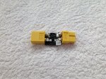
In this copter I use the Lemon telemetry module, which has a current sensor, to be hooked up between the battery and the controller (in this case the power distribution board). But I always "fight" with routing the battery cables and this sensor is rather large. And non-flexible. Which gives a little trouble guiding wires.

So I "adjusted" the length :p

IMG_8669.JPG

IMG_8670.JPG

IMG_8675.JPG
 
Last edited: