Building the FT Mosquito Master Series 50“

Burnhard

Well-known member
Found a solution to keep the doors open. Stumbled across a build report from @Pieliker96 on a Caribou yesterday night. Tried that in my test set-up today and it works. Will need to work on the optics.
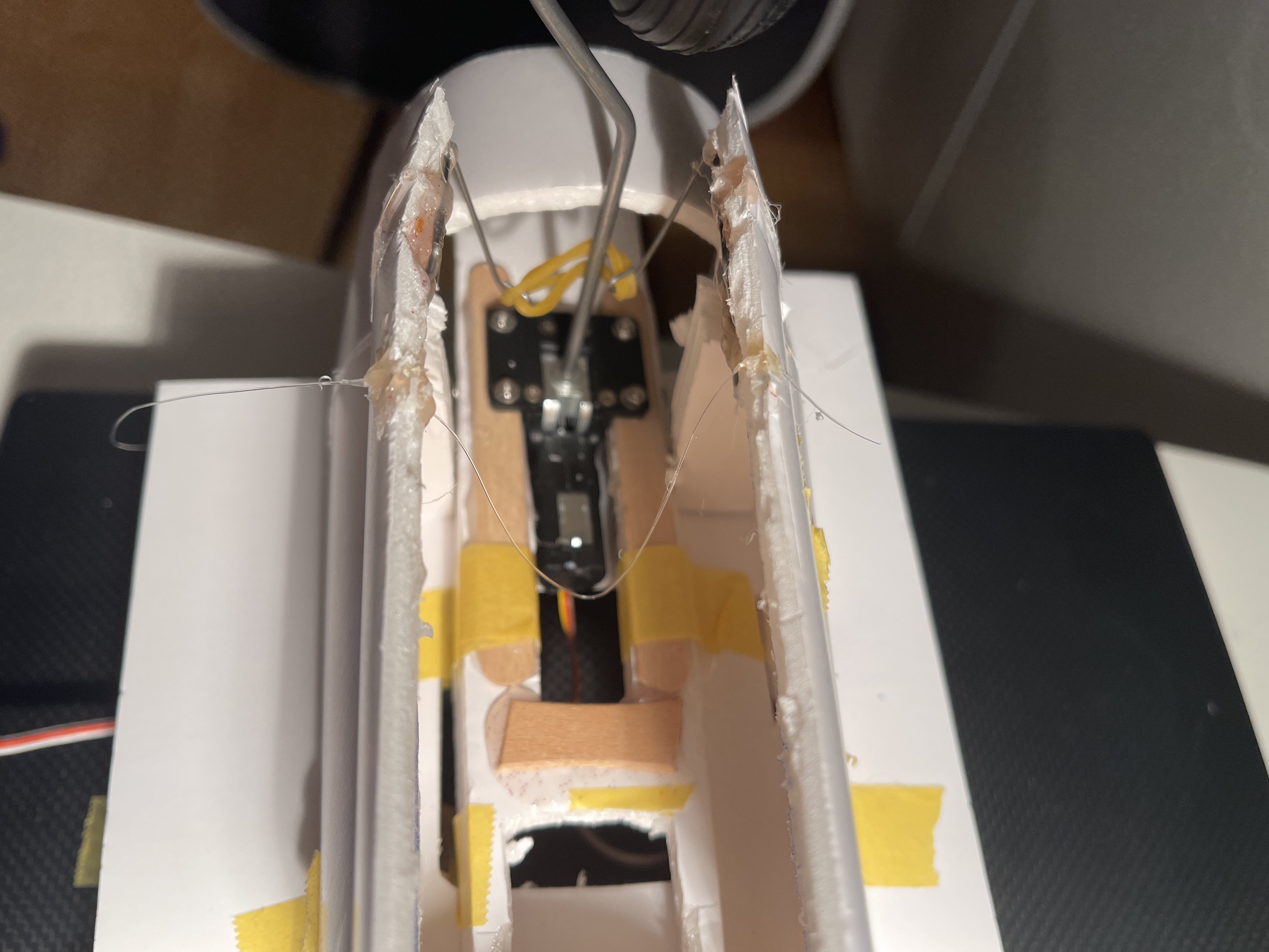
image.jpg
 

Burnhard

Well-known member
More progress today. After doing quite a bit of testing, today I finalised both nacelles. Well, not completely. I am yet to do the closing and opening mechanism.

Also started on the wings. Will add a bit of carbon and start working on the flaps mechanism tomorrow.
47FE3031-0D89-4370-A3F9-379CF26AB3AC.jpeg
 

Attachments

  • 861C4921-BE7D-4D38-8AE7-0CE3B124025B.jpeg
    861C4921-BE7D-4D38-8AE7-0CE3B124025B.jpeg
    1.6 MB · Views: 0
  • 9963EC07-4759-42BE-AF19-2C7879397AD5.jpeg
    9963EC07-4759-42BE-AF19-2C7879397AD5.jpeg
    3.3 MB · Views: 0
  • EFC423E3-57DA-4839-8518-5228BE01AC43.jpeg
    EFC423E3-57DA-4839-8518-5228BE01AC43.jpeg
    1.7 MB · Views: 0

Burnhard

Well-known member
Started work on the wing today. Added a bit of carbon fibre to avoid a folding wing in case the wooden spar gets to much stress.

Also finished the preparations for the flaps. I started with a model of the lower wing. First tried the version with one servo for both flaps. That did not work to well, as it resulted in a rather strange angle of attack and almost no power. I then decided to go for a solution involving one servo per flap. I had some micro servos left and decided to use these instead. The wing is rather tight so bigger ones would probably not fit anyway. I went for a pusher set-up where the pushrods will be inside the wing. However if that does not work too well, I can still go for a puller set-up. The other benefit of the two servo set-up is that these remain accessible. In the version with the one servo, that servo would have been hidden under the nacelle and would have been rather difficult to maintenance.

Will close the wing tomorrow. Once the wing is closed, will add the aileron servos and then the nacelles.
DC921E53-8A3A-4E64-A109-F94C6F6443D0.jpeg
 

Attachments

  • 6D965E4B-7C8D-41EF-B229-B116243A81B2.jpeg
    6D965E4B-7C8D-41EF-B229-B116243A81B2.jpeg
    1.4 MB · Views: 0
  • 513B46FB-FDC6-4582-ABFE-35A65FCBFF1A.jpeg
    513B46FB-FDC6-4582-ABFE-35A65FCBFF1A.jpeg
    1.5 MB · Views: 0

Burnhard

Well-known member
Yesterday I closed the wing and cut the flaps on the upper wing skin. After that I added a small piece of thin cardboard to each flap to close the gap that opens when the flap moves downwards. The piece slides in the upper wing skin when the flap closes.

When I go to the last flap disaster struck. On the last flap the flap did not fully close when moving the flap back up. I did a lot of testing with moving flaps down and then up again, when suddenly the next flap started failing and I got a low voltage warning from the receiver. I first thought I have a depleted battery but when I turned the wing upside down I saw that the glue around some servos had melted and even worth, two servos got so hot, that the plastic of the servos started to melt. So much about stress on the flaps servos we discussed further above. Three servos are toast.

So I had to take all four flaps servos out and replaced these by larger 12g servos. Luckily I wired the original set-up in a way so that the servos and the extensions where long enough to re-connect the new ones. The new ones move the flaps much easier. I did a bit of testing and luckily the new ones don’t even get warm.

After that I did add the aileron servos. Next stepp is to add the nacelles.
F2363333-8F2E-4721-BA0B-2E80AE9991FC.jpeg
 

Attachments

  • A76355A2-156B-401E-BF42-EEA18A912F30.jpeg
    A76355A2-156B-401E-BF42-EEA18A912F30.jpeg
    1.5 MB · Views: 0

quorneng

Master member
Burnt out flap servos just testing?
This does suggest that much effort is required to simply make them move regardless of any additional aerodynamic load that will arise when they are deployed in flight. Given each flap only weighs a few grams perhaps some improvement to the "mechanics" of their movement would improve their reliability.
I like to see any control surface when disconnected from its servo free enough moving so it drops under its own weight. Then I know the majority of the servo's force will be available to counter aerodynamic loads. ;)
 

Burnhard

Well-known member
Burnt out flap servos just testing?
This does suggest that much effort is required to simply make them move regardless of any additional aerodynamic load that will arise when they are deployed in flight. Given each flap only weighs a few grams perhaps some improvement to the "mechanics" of their movement would improve their reliability.
I like to see any control surface when disconnected from its servo free enough moving so it drops under its own weight. Then I know the majority of the servo's force will be available to counter aerodynamic loads. ;)
Probably need to change my design. Will do on the next one ;-)
 

Burnhard

Well-known member
Sealed all open foam surfaces on the wing today and added a strap of balsa to the leading edge. The one thing I don‘t like about the Master Series is that open gap on the leading edge. On the DC3 I tried to close that gap by wrapping paper around but the outcome was mediocre as the paper gets out of form once it soaks in the glue and then you have to work out any wrinkles. The result with the balsa seems to be better.
AE599F7A-BB5D-40FC-B655-3D29E070D304.jpeg
 

CrshNBrn

Elite member
A fella at the club added similar triangular shapes to his leading edge, claiming that it diminished his plane's nasty stall characteristics. Maybe you'll get a little added benefit beyond your smooth leading edge. I have the same issue with the MS planes.

I've been using the leading edge technique on some of the newer 13th Squadron plans (e.g. Helldiver, DH88, Betty): cutting 45* bevels on top and bottom wing sections, then using blue tape across the leading edge to hold the sections together before folding over for gluing. When it works, it makes a solid, rounded leading edge that looks sharp and is strong. On the other hand, when it doesn't (like when the tape slips a bit), it can lead to a nasty open gap on the LE that is hard to fix, so be careful if you ever try it. It is worth the effort!
 

Burnhard

Well-known member
A fella at the club added similar triangular shapes to his leading edge, claiming that it diminished his plane's nasty stall characteristics. Maybe you'll get a little added benefit beyond your smooth leading edge. I have the same issue with the MS planes.

I've been using the leading edge technique on some of the newer 13th Squadron plans (e.g. Helldiver, DH88, Betty): cutting 45* bevels on top and bottom wing sections, then using blue tape across the leading edge to hold the sections together before folding over for gluing. When it works, it makes a solid, rounded leading edge that looks sharp and is strong. On the other hand, when it doesn't (like when the tape slips a bit), it can lead to a nasty open gap on the LE that is hard to fix, so be careful if you ever try it. It is worth the effort!
I guess you have to be very careful with the tape. On another video I saw somebody using a small iron to round the edges but I do not have one of those. The other thing I did in the past was to sand the lower wing skin but this does not work with the speed build kits as the laser melts the foam for about 1 to 2 mm which is too much to get to a round shape. This only worked when I was hand cutting the foam board from plans. Hope the balsa solution results in less clever comments on aerodynamics at my local flying club ;-)
 

Burnhard

Well-known member
The basic build is done! After the wing was done the next steps went reasonably quick. Almost ran out on servo ports on my 9 channel receiver. Decided to use a separate channel for each side of the flaps and also used a separate channel for the tail wheel so that I can trim it out against the rudder. Had no channel left for a working bomb bay. However I prepared one side of the lower fuselage to later include a maintenance hatch.

Next steps will be:
-filling any wrinkles and gaps with light weight filler
-making a pair of spinners from xps foam (I also got the FT spinners but the styrofoam is not to great to sand down
-thinking of a paint scheme (I like the one with the read and white tail)
-painting. The recent post from @Baron VonHelton makes me wonder whether I should get an airbrush

A dude at my flying club introduced the idea of maidening the aircraft prior to painting in case it does not fly great. I tend to ignore that advice.
BFC3A98C-268F-4500-AA1C-F90F2E27277A.jpeg
 

Attachments

  • 197496B1-A5F2-4CBE-8A01-333985839620.jpeg
    197496B1-A5F2-4CBE-8A01-333985839620.jpeg
    3.7 MB · Views: 0
  • F40001C8-21B9-4AD8-813D-AE81CEC023C8.jpeg
    F40001C8-21B9-4AD8-813D-AE81CEC023C8.jpeg
    3.7 MB · Views: 0
Last edited:

Opus

Member
The basic build is done! After the wing was done the next steps went reasonably quick. Almost ran out on servo ports on my 9 channel receiver. Decided to use a separate channel for each side of the flaps and also used a separate channel for the tail wheel so that I can trim it out against the rudder. Had no channel left for a working bomb bay. However I prepared one side of the lower fuselage to later include a maintenance hatch.

Next steps will be:
-filling any wrinkles and gaps with light weight filler
-making a pair of spinners from xps foam (I also got the FT spinners but the styrofoam is not to great to sand down
-thinking of a paint scheme (I like the one with the read and white tail)
-painting. The recent post from @Baron VonHelton makes me wonder whether I should get an airbrush

A dude at my flying club introduced the idea of maidening the aircraft prior to painting in case it does not fly great. I tend to ignore that advice. View attachment 224550
Your workmanship is first class. The flaps look great. I am anxious to hear how your first flight goes.
I made my first flight today and I am pleased. I was surprised to discover that it was actually nose heavy with a 2250mah 3 cell. I checked the horizontal stabilizer and it is on the same plane as the wing so there was no pitch error there. I also switched to the servoless retracts like you have and they work well. Plane had plenty of power with the supplied motors/esc. Elevator and ailerons have lots of authority so plan on adding expo.
Now to add an FPV camera! :eek:) http://youtube.com/user/sourdough60/
 

Burnhard

Well-known member
Your workmanship is first class. The flaps look great. I am anxious to hear how your first flight goes.
I made my first flight today and I am pleased. I was surprised to discover that it was actually nose heavy with a 2250mah 3 cell. I checked the horizontal stabilizer and it is on the same plane as the wing so there was no pitch error there. I also switched to the servoless retracts like you have and they work well. Plane had plenty of power with the supplied motors/esc. Elevator and ailerons have lots of authority so plan on adding expo.
Now to add an FPV camera! :eek:) http://youtube.com/user/sourdough60/
Quick question on the CG. Where do you measure that?

I measured between the fuselage and the nacelle. With a 4S 3400 it seems to balance just after the recommended 66,7mm. There is no way mine would balance even close the recommended CG with a 3S 2200.
 

Burnhard

Well-known member
Ive had many planes live their entire lives without paint! Lol
The only plane that did not get a proper paint job is our first tiny trainer build. However the kids did a bit of pencil painting with it and after flying in snow a year ago, this now looks pretty psychedelic. Will need to find a picture of that one.
 

Opus

Member
Quick question on the CG. Where do you measure that?

I measured between the fuselage and the nacelle. With a 4S 3400 it seems to balance just after the recommended 66,7mm. There is no way mine would balance even close the recommended CG with a 3S 2200.
I also measured between fuselage and nacelle. With the 2250 3cell the balance point was 83 mm. THAT was the configuration on the first flight and it required all the nose-up trim I had to trim it level. So, the proper C/G should be something more like the 66.7mm.
 

Burnhard

Well-known member
Started work on the two spinners today. I got the FT foam spinners but these were slightly deformed from the shipping and the styrofoam is not great to sand. Also I wanted to use the three blade props and the FT spinners are for two blade only.

The Mossi spinners will be made from xps foam which is great to sand but als creates a giant mess. Somewhere on youtube I saw how these can be made from bottle caps and the top screw part of a PET bottle. I have tried that once before and it works pretty well. Did the preparation work today and will start sanding down later this week. Waiting for good weather as I want to do that outside.
5631674A-4A06-4028-9744-96ECA6A11EE8.jpeg
 

Attachments

  • D3C3A722-8B13-4FFC-994F-19BFA555CCA6.jpeg
    D3C3A722-8B13-4FFC-994F-19BFA555CCA6.jpeg
    2.5 MB · Views: 0
  • A506DACB-F469-4ECD-A11B-E37BD49F9175.jpeg
    A506DACB-F469-4ECD-A11B-E37BD49F9175.jpeg
    2.6 MB · Views: 0
Last edited:

Opus

Member
Update on C/G: On the first flight the plane needed all the nose up trim available (see above). I cut and re-positioned the horizontal stabilizer so that it now has about 3 degrees tail-down/nose-up input, relative to the wing cord. With the 2250 3 cell the C/G is at 81.5 mm from the leading edge, measured next to the fuselage. Pitch trim is perfect. With about 3/4 throttle and elevator neutral it flew straight and level with no added pitch trim.
Tail1.JPG
tail2.JPG