
You are using an out of date browser. It may not display this or other websites correctly.
You should upgrade or use an alternative browser.
You should upgrade or use an alternative browser.
First Bat Bone Build
- Thread starter DDSFlyer
- Start date
DDSFlyer
Senior Member
Yeah I've got two full strips (111 LED's) on my super cub from hobbyking. They're the RGB with the 9 mode controller, it's ridiculous at pitch dark! I was thinking of going white facing forward, then red on the left back and left tail, then green on the right back and right tail plus white on the bottom? I have some dental loupe lights for spot lights I was gonna mount later but I'm not sure the voltage on them so I dunno if I want to mess with those and just get some circular LED lights from HK like Stuart has on his dead cat quad (which is definitely a future project I want to build)
DDSFlyer
Senior Member
Question about my breakout cable. Should I make in addition to the 6 black and red bullets for the ESC's, two JST connectors for lights and the KK2.0 or 2.1 voltage alarm input? It would make it cleaner right? And doing this instead of making it come off the balance connector would be better since it would be coming off the main power instead of just one cell, did I get that right?
If you'd run your LED's at 12v off the balance port (I wouldn't recommend otherwise) vs. running through the distribution board, then electrically those setups are the same -- the power just comes through a different plug.
I run my lights off a separate harness that plugs into the balance port, but that way I can choose whether I want the lights on or off. You're choice -- one less hookup if you want it always on, or keep the option.
My voltage monitor runs from the power + connector . . . and the ground plug is left disconnected in that cable. **Be careful with this.** if you reverse connect the voltage monitor it will short the battery *through* the kk2, likely resulting in a burned out kk2 board and a 2 week wait for replacement. I recommend cutting the "-" pin of the voltage reference connector on the kk2 board(triple check before you do") ), then connecting a single wire between the "+" connector and the hot side of your power harness.
), then connecting a single wire between the "+" connector and the hot side of your power harness.
I run my lights off a separate harness that plugs into the balance port, but that way I can choose whether I want the lights on or off. You're choice -- one less hookup if you want it always on, or keep the option.
My voltage monitor runs from the power + connector . . . and the ground plug is left disconnected in that cable. **Be careful with this.** if you reverse connect the voltage monitor it will short the battery *through* the kk2, likely resulting in a burned out kk2 board and a 2 week wait for replacement. I recommend cutting the "-" pin of the voltage reference connector on the kk2 board(triple check before you do
), then connecting a single wire between the "+" connector and the hot side of your power harness.DDSFlyer
Senior Member
Crafty Dan,
Do you have any pics of what you're talking about with the voltage monitor? Is your setup for the KK2.0 or the KK2.1? I've been reading up on the 2.1 and hearing about the risk of burning out boards by reversing polarity and has got me a little nervous about it. Just connecting a "+" to a wire or pin I didn't know that would work and would be nice to see.
The way DHDSRACER on youtube sets up a JST wire for the voltage input on the KK2.0 board was what I was prob gonna do with my KK2.0 board as well, but with the KK2.1 board I'm under the impression that they already added the pins on the board so that you can just plug straight into the board and that was why people are at risk for pluggin it in reverse and blowing up their boards (am I correct in saying that?)
Also, on another note, connecting ESC's to the KK board I've seen some setups where they are keeping the servo wire of M1 and connecting that normally, then with M2 and M3 either unplugging the power (red) wire and/or the ground (black) and just keeping the signal wire (white) plugged into the board. Do I have that right? Then with the tricopter, where do I plug in the servo for the tail? I have to see if I need an extension for that as well.
It's been awhile since they first came out with the bat bone and I got introduced to David's tricopter builds that I'm trying to refresh my memory from what I tried to learn and now finally put it to use on this first build of mine. Thanks for all of the help!
On a KK2 the servo lead for a tri-copter connects to M4.
I've got both, but the one to worry about is the 2.1. I've got "clean" builds, so all of my electronics are hidden . . . my pics won't help.
Basically, on the 2.1 board, the outer pin on the voltage connector is the measurement pin. They mounted a ground reference pin right next to it, but it's connected to the same ground plane the ESCs, servo, and receiver are connected to. two things:
- you don't need a ground for the voltage monitor, because the ESC's are already providing a connection to battery "-" for the whole board.
- Because the ESC's are connected the board's ground plane to battery "-", if you accidentally hook up battery "+" to the wrong half of the battery monitor connector, you've now connected + to - through the board's ground plane and ESC. something's got to give, and I'd bet it won't be the cheap servo wire
So! clip the "-" pin on the battery monitor connector on the kk2.1 (you *don't* need it!), and only wire up the "+" connector to the hot side of your power distribution (harness or board).
As for the motor pins, CR is right. servo goes in M4. front left goes in M1, front right in M2, and tail in M3 . . . but what about the pulling pins on connectors?!?
M1 power is isolated form M2-8 power, and is used to power the kk2 and receiver. M2-8 are connected together, so the servo on M4 can take it's power from one of the other ESCs. people have been pulling the power connectors from the ESC's so they don't fight. each ESC has it's own UBEC, which wants to drive the voltage at the pin to what it thinks is 5v. if you connect two of these together and they're pretty close to agreeing what 5v is, no problem. if they're off a little more, they'll start to fight -- the one who want's it high will source more current, the one who wants it low will sink that current, slowly wearing each other out . . . or worse, quickly wearing each other out!
On the whole this is pretty rare, but it can happen.
So! the best thing you can do about this is connect M1, M2 and M4(servo) as normal, then pull the middle pin out of M3's connector (power) and tape it off, and plug in the M3 connector with only the 2 outer pins, like normal. Leaving in the ground won't hurt anything . . . and leaving in the power *probably* won't hurt anything.
DDSFlyer
Senior Member
So on the voltage connector on the KK2.1 board (it's the second one down from the top left, under the speaker pins) the pin closer to the center of the board/right pin/inner pin is the one I would clip at the base right? Then I would solder in a JST lead with just the red power wire to the harness (or balance connector) correct? Seems easy enough...but nerve wracking. Wire clippers should do the trick right?
As for the ESC connections. Just M3's power wire needs to be disconnected so that the board and the servos will get power and not fight each other. This is something I remember forgot the FT Cruiser build that I did, where I pulled the power wire from the second ESC as well and taped it off. Just needed to figure this out for multirotors now. If I was doing this with a quad and the KK board would I only need M1's power and not the other 3 or M1 and M2 and not the other two?
Thanks again for all of the useful info. Maybe I'll take a pic of the final clipping of the board pins to show what was done (right or wrong it would be a helpful pic...
No Sweat! Lets get this tri ready for the air!
Completely understand -- hate cutting pins on mine, but it is recoverable if you mess up . . . just requires some desoldering
Pretty much right, but just to double/triple/quadruple check . . .

Keep the pin the "Voltage detection +" red line points to, and clip the one next to it. It's just a soft metal pin, so wire cutters are fine as long as they're not so big they can't get to it.
Yes, for the tri config, to protect the UBECs you only need to tape off the M3 power pin. on a quad/V-tail, you'd need to do both M3 & M4. Technically nothing magic about M2 being left connected, just keep only one power out of M2-8 plugged in at a time.
DDSFlyer
Senior Member
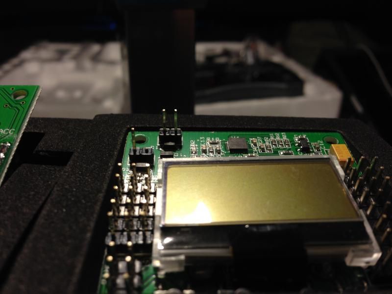
Thanks for the help CraftyDan! I've got the KK2.0 set up for low voltage detection per DHDSRACER/RC Manchild. Also, did the clipping of the "-" pin on the voltage detection connector on my KK2.1 boards. Hopefully they both will work great, I'll probably try and compare them once I can get one of them to work correctly on this try. And now for the pics.
KK2.0 on the left KK2.1 on the right

Close up of the clipped pin on the KK2.1 voltage detector connector
KK2.0 on the left KK2.1 on the right

Close up of the clipped pin on the KK2.1 voltage detector connector

DDSFlyer
Senior Member
Yep, the KK2.0 has v1.6 on it...I think it was the latest one. I did that a month or so ago while waiting. The KK2.1's were flashed with Steveis beginner v1.12 or something like that. Looks like the motors and ESC's are waiting for me at the office, but the international order from HK has misc things but the main thing I will need is the Male to Male servo connectors so I'll be stuck at that step for prob the rest of the month, boo. Maybe I'll see if I wanna spend the cash at the LHS if I get impatient with the build
EDIT** I'm so impulsive with this buy...just bought some male to male servo leads on ebay for 8 bucks...only a couple bucks more than HK but I'll get them by the end of the week!
EDIT** I'm so impulsive with this buy...just bought some male to male servo leads on ebay for 8 bucks...only a couple bucks more than HK but I'll get them by the end of the week!
Last edited:
Value Hobby has the male-male leads for $2.50. . . and they ship in US pretty fast.
Also have great prices on props (you did get enough? right? yes? you probably need more )
$4 shipping though . . . anything else you need to stock up on?
Also have great prices on props (you did get enough? right? yes? you probably need more
)$4 shipping though . . . anything else you need to stock up on?
DDSFlyer
Senior Member
I'll have to bookmark Value Hobby, didn't know about them. I ordered 4 packs for each prop in 8x4.5 and 9x4.7. Green CW,Green CCW, and Black CW. Plus I think I have even more 8x4.5's lying around. Gonna have a field day when I get those props in and just take a night to balance them all watching the TV hehe
DDSFlyer
Senior Member
Haha! Actually, time is not my friend. But I did sit down and balance 16 props while watching some tv. Blades are easy to balance...hubs are a pain! Hopefully my hot glue will stay on when flying. Who knows if the props will last that long anyways...
I may be able to drill the holes in my booms and get to building, still waiting on the Rx to KK board servo leads though so I will only be able to mock up everything and hopefully get to making my breakout wire to appropriate length and extra cables for it
I may be able to drill the holes in my booms and get to building, still waiting on the Rx to KK board servo leads though so I will only be able to mock up everything and hopefully get to making my breakout wire to appropriate length and extra cables for it
DDSFlyer
Senior Member
AHHHH...just my luck. I've left everything in the bag because I didn't have all of the parts to start the build. So I finally have some time to get everything out of the box and what do I find? I'm missing the two straight mounts in the bag. I ordered a bunch of stuff at the same time for christmas and just set this project aside didn't even thinking about checking my order. Called up Flite Test and talked to Alex! He apologized for the inconvenience and corrected the problem and is sending them out my way with some new stickers for free! Flite Test guys ROCK!!!! Now I just have to stare at my bat bone and have another reason to wait on it...oh well
DDSFlyer
Senior Member
Lol! Well I've at least finished mounting the tail boom, tilt mount and servo and attached it to the main frame. I found out I only have 6" servo extenders so I may have to get a 12" or just use two 6" ones for now, but I have the male to male servo leads in now and I need to make my breakout cable, and see if I need to extend the ESC to motor or battery leads or just make a longer breakout cable (the Afro ESC's came presoldered with bullet connectors on all leads but pretty short ones. I'm super excited! Although while getting half way through the servo install I had to stop and when restarting I lost one of the control rods...glad I had extra wire and just replaced both to match....just bugs me when I lose something. She coming together though. I really should've built the frame first while waiting for the electronics. Then I would be farther along...
Similar threads
- Replies
- 422
- Views
- 14K