Foam wing DLG electric

bracesport

Legendary member
Hi There fellow flite-testers, I'm Phil from New Zealand and I have been posting my article with a view to working it through in a few parts. I'm thinking that as 'part 2' has been slow to get approval that maybe it is frowned upon to post incomplete articles. So, I thought id move to the forum as that might better place me for feedback along the way!

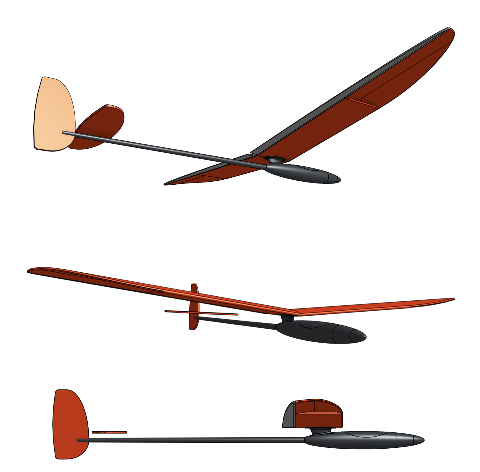
This is where it all started - 'Wacky Wednesday' - it all started with a shoe on the wall (to quote Dr Suess). I just love the design of Vladimir's Models Blaster v2 DLG, so given its wacky Wednesday, I thought I would make a project of it with a Flitetest style foam board wing and tail, an RP'd front fuselage, a carbon fuselage tail, and a motor with a folding prop! The most interesting feature of this very cool plane is the main wing mount which is a standoff from the front fuselage - at this point, I can see that will be the tricky bit!

https://www.flitetest.com/articles/foam-wing-dlg-electric

0.png
1.png
2.png
 
Last edited:

bracesport

Legendary member
To recap - I wanted to build a DLG styled electric glider - this is only my third build, but I wanted it to be ambitious - I think DLGs are quite sexy looking and I like the idea of the flaperons so that narrowed the field quickly!

In the article, I was glueing the top foam wing skins with a view to preparing for the fibreglass! Compared to my first foam wing glider with a similar wing size and a chord thickness of 24mm, this wing is only 18mm thick - I based the size on the blaster 2 aileron template, so hopefully, it will be good enough!

I decided to add the ailerons to the foam blanks with the hope that they will shape better and help support the wing during the glassing process. The plan will be to glass the top first (including aileron) then prep and glass the bottom. After glassing, I will sand and paint, then separate the ailerons from the wing. Then I will reattach the ailerons with a bead of silicon to create a hinge (apparently that works well)!

Ailerons are reattached and roughly sanded, however, with the benefit of hindsight I could have made the complete top wing from one piece including the aileron. If I did that in the future, I think I would use spray glue for the back edge as it was difficult to get the hot glue onto the very this section - just a thought!

I still need to sand the leading edges and tidy up the top surfaces before joining them at the centre and attempting the glassing of the top surface.

Sadly some hot melt that migrated to the top surface when I joined the ailerons on so I cut it out and mixed some foam sanding dust into a small amount of epoxy to act as a filler. I will sand them in the morning and go from there. Hopefully, the epoxy will help stiffen the thin edge of the wing as the top surface is glassed! I was quite anxious overnight, but it all turned out rather well.

Glueing the wing halves and adding the centre wing mount with hot glue was a bit of a mission but with the 12 dihedral jig, it was easier to get it aligned. The central mount fitted well but was a tad too tall on the top surface so needed some sanding. I think it was due to the CAD being at 6mm for the foam sheet, but once the paper was removed the total thickness was less (next time I will plan for 5mm sheet thickness)!

I have opted for Wests 105 epoxy with the 201 hardeners (5:1 ratio) and will go with the 'wet' method which means I will roll on the epoxy before adding the 76g cloth and roll it into the epoxy. I also plan to use the toilet paper method to remove excess epoxy. One more final sand of the leading edge tomorrow morning then the Epoxy and glass will go on!

A new day - the top skin is on - all went pretty smoothly given it was my very first ever attempt at fibreglass work!

Sadly I chose a woven carbon fibre tape and the edges ended up being a bit thick under the glass so I will have to sand that down and recoat with epoxy in that area. Also, I couldn't get the leading and trailing edges to wrap so I trimmed them back for now.

We live and we learn!

Both top and bottom surfaces have been glassed with one layer of fibreglass and a carbon fibre strip. The top surface required a serious sanding to thin down the edges of the tape so in its finished form they look a bit messy. Sadly I got a bit of Carbon sanding dust contaminating the fibreglass. Nevertheless, the finished product is light, stiff and rather impressive in my humble opinion!

The aileron edges are very straight and the wing tips are thinned nicely!

Total weight unsanded is 280 grams (9.88 ounces).

IMG_4664.JPG
IMG_4665.JPG
IMG_4674.JPG
IMG_4676.JPG
IMG_4677.JPG
IMG_4678.JPG
IMG_4679.JPG
IMG_4680.JPG
IMG_4701.JPG
IMG_4707.JPG
IMG_4706.JPG
 

bracesport

Legendary member
This is a partial recap of the fuse build so far.

To make this electric, the trick will be getting all the gear in the front. I have decided to make it with Ailerons and elevator only (bank and yank I think they call it)! I want the three servos required in the fuselage so I can easily swap wings when they inevitably get damaged!

I've split the fuselage horizontally to prepare the interior and clean out all the RP build material, and attach the tail boom before rejoining the halves. The nose reinforcement also provides the front support for mounting the fuselage halves and eventually the front motor cover. At some point, you just need to get started, so I fired up the RP machine and made some parts. The wall section and ribs of the ABS fuse are 2mm and given that RP parts tend to have voids in the walls the parts turned out quite light. I am hoping the resin will penetrate the ABS to further strengthen the body.

So far so good - I glued the tail boom into the fuselage after first making a hole that will eventually allow the elevator pushrod to exit from the boom. The servo arm sits quite high in the fuselage so I need the slot to allow the push rod to angle from above the boom down into the boom at a reasonable angle!

Next is the epoxy - At this stage, I am planning to use some glass through the centre of the interior, and all of the exterior. The wing support needs some thinking as it is the weak point in the structure, I should put some strips of carbon fibre to stiffen it in some way.
Screen Shot 2018-11-22 at 8.27.01 AM.png
Screen Shot 2018-11-22 at 8.27.12 AM.png
Screen Shot 2018-11-22 at 8.20.30 AM.png
Screen Shot 2018-11-22 at 8.20.39 AM.png
Screen Shot 2018-11-22 at 8.20.48 AM.png
Screen Shot 2018-11-22 at 8.20.56 AM.png
Screen Shot 2018-11-22 at 8.21.11 AM.png
Screen Shot 2018-11-22 at 8.21.31 AM.png
Screen Shot 2018-11-22 at 8.21.38 AM.png
 

bracesport

Legendary member
This could be a tad controversial as I started out thinking DLG, but as I research more I'm finding the weight of my plane (targeted at <1.0kgs) might be an issue to really cut it as a DLG, so I've been experimenting on CAD with a 'V' tail version. The 'V' tail is a very sexy style (as is the DLG) and given it will be hand launched with the prop spinning I'm leaning towards the 'V'!

Any input welcome!
compare.jpg
 

Paracodespoder

Elite member
Nice looking little plane you got there! I’d go with the v-tail as it looks just a leetle bit better. Looks kinda like a hot liner with the v-tail.
 

bracesport

Legendary member
Nice looking little plane you got there! I’d go with the v-tail as it looks just a leetle bit better. Looks kinda like a hot liner with the v-tail.

funnily enough about 15 years ago I bought a 1.6m glass V tail hot liner - never flown it - too scared of its +200kph flying speed! Oh, and at that time I hadn't learned to fly - just starting again now with these two slow fliers

fly.jpg
 
Last edited:

bracesport

Legendary member
Learning to fly has been a bit hit and miss for me, I've got some old school gear and my planes are home built! I have a JR X378 with mode one, and I have been uncomfortable with the steering in my left hand. I have been researching the net to see if I could change modes, and although some say it is possible, it does not seem my version has that functionality.

So last night I did some surgery on my TX! It was a relatively easy operation to switch the springs and such so the throttle on the right could be swapped with the elevator. As the RX has a common bus for the power I just reversed the throttle and elevator accordingly and everything worked a treat - I now have a poor mans mode 2!

My plan is to run flaperons on the glider build (or at least have that capability) so at some stage, I will need to do some mixing of the ailerons with the elevator (throttle channel) so that might get interesting!
 

bracesport

Legendary member
QUESTION: My plan has been to have the servos inboard the fuse as shown above, but as I ponder the options, and given the wing is fastened to the fuse, maybe the best approach might be to put the servos in the wing and keep things simple? Any input welcome.
 

buzzbomb

I know nothing!
As is not unusual for my posts, I have no clue how to answer your questions. I just wanted to say "Wow!" I'm glad you ported your thread up here. That is a beautiful, skilled and impressive build. I very much look forward to more.
 

bracesport

Legendary member
Sadly my RPs (rapid prototype) of the fuse shown above have deformed while sitting and waiting for me to finish it! I am putting new parts on the machine today! From there I’ll strip the current parts from the boom and have another go! Challenges at every stage are there to test our character!
 

bracesport

Legendary member
Where are you planning on mounting the Rx and ESC?

I am thinking the Rx and ESC will be on top of the battery. I also have a smaller two cell battery if things get tight! Alternatively if I put two Servos in the wing I’ll have a truck load more space. Seems like the pro DLGs have a smaller nose than mine so I am hoping there will be enough space!
 

Craftydan

Hostage Taker of Quads
Staff member
Moderator
Mentor
QUESTION: My plan has been to have the servos inboard the fuse as shown above, but as I ponder the options, and given the wing is fastened to the fuse, maybe the best approach might be to put the servos in the wing and keep things simple? Any input welcome.

That's a far simpler approach -- it's fairly easy to cut and mill out pockets and channels under the glass for your servo, wires and linkages, then tape over the servo pocket on the underside. I tend to use a fresh #11 blade to cut the servo outline in the glass, peal back the patch, then mill the pocket with a dremel and a milling bit. keep the servo on-hand to test fit against how deep you've milled the pocket so-far. once that's done, you can use a bent-paperclip and a lighter to melt out a channel to the center, and pop a hole in the glass where they come out. I typically add a masking tape wrap around the servo as an epoxy-condom (so I can remove the servo later if needed). fish the wire through, dry fit, and when happy a small dab of epoxy on the inside, and packing tape on the outside. If you're handy with wiring, you can also join the two servos together on the same power/ground rail and swap out the two servo connectors for a single four-pin connector to simplify the flight setup/tear-down further.

It's actually a bit of a shame your hinge is on the top, since if you had gone with the bottom, you could have run a top-drive arrangement, which only leaves a bit of the control horn sticking out into the wind and nothing else . . . but with a powered plane you can afford a bit of extra drag from the linkages. Something to consider on a future wing.

Something else to consider on a future wing, is embedding a hinge tape under the glass in your layup (Kevlar is the typical go-to, but I've had reasonable success with a thin nylon from a fabric store), then you glass and layup the wing as a whole. once cured, cut the hinge on the opposite side, crack the glass along the hingeline and bevel. Easy peasy.

One point on your layups . . . A little 3M-77 will go a long way. When dealing with patches and strips that may fray, a light spritz of '77 between the trimming and placement will not only hold the cut edges in line, but it makes it easier to set the patch into your layup. Tack one side down into the layup in one spot, and smooth the rest in. That being said . . . I'm frequently lazy and skip this . . . and regret it.

Also, add on a vacuum bag and mylar covers and you can do a wing half in one go. The layup goes on the mylars (fabric, epoxy, blot), then you apply the mylars over the foam core and drop it in a bag to suck it down. It seems like an expensive bit of tooling, but you can use food-saver bags (they come in long strips), so long as you keep the wing cord reasonable. the gear for those is usually fairly reasonable, and can be sold to the wife as a "kitchen expense" ;) The sealer on those means you don't have to keep the bag constantly under powered vacuum, so you set the wing halves somewhere warm and flat until cured and cut the bag open when done.

Once the halves are done, you don't need a dihedral jig -- sand a bevel in the root for your chosen dihedral (1/2 on each side, naturally), cut pockets for epoxy around your wing-mounts, then tape them together with packing tape on the bottom to form a hinge. You then use that hinge + gravity to hold the dihedral as the epoxy cures. mix up a small batch of epoxy/talc (or glass beads) to get a wet puddy, fill the pockets, and coat the roots, and close up the seam. Rest each wingtip on a 2x4 with the wing root floating and your bevel/tape hinge will naturally set your dihedral. After it cures, peal the tape back and run a 3-4" strip of glass or carbon weave (on the bias, please) all the way around the root (don't forget the 77), and wet/blot it with straight epoxy. A single thickness strip will be more than enough to make the root solid.

You're well on your way to a nice electric glider. I expect she'll be nearly as fun as a hand-launch . . . but there's always the next build ;)
 

bracesport

Legendary member
Hi there Crafty Dan, thanks for the insights! Having almost made one wing I'm already planning the next! I like your idea with the vacuum sealer for a bagging device - I'll need to look into that a bit more! Sounds like I'm putting those servos in the wing!

The centre join of my wing was a tad rough, so last night I put a saw through it (yikes) and am shortening it by 2.5cm per side at the root. I'll consider rejoining it as you described! It will! now be a 1.45 wing!

Also, the new RP's (ABS rapid prototypes) of the fuse are done so I need to make a few new posts!
 

bracesport

Legendary member
Here are my new parts off of the RP (ABS rapid prototype) machine. I have chosen a differing approach as keeping the RP's tubular has made them stronger and a tad more accurate.

The plan is to only mount the motor and ESC in the front section and fit the battery, Rx, and tail servo into the rear fuse section using the tongue as a mounting platform. The front section will slide over and will be screwed (or taped) for flight

I have also made a wing joiner which allows me to mount the wings without cutting the dihedral.

IMG_4807.JPG
IMG_4805.JPG
Screen Shot 2018-11-30 at 8.14.42 AM.png
 
Last edited:

bracesport

Legendary member
Saturday here in NZ and its a great start to the first day of summer! My son and I have been building chuck gliders and finally, we got the trim right and had some awesome flights (and some ball kicking)!

Also, I had some time to soak the new fuse parts in MEK (acetone) to bind the internal structure of the RP parts making them (hopefully) more robust. After that, I sanded the fuse mount to get a perfect fit for the boom taper and epoxyed in the C/F rod and trimmed the length to 60cm. If I choose to go with the V tail I will use the tail mount shown in the images. It feels quite strong so I am thinking to try this one without any resin and glass.

Painting underway.


IMG_4851.JPG
IMG_4852.JPG
IMG_4854.JPG
IMG_4856.JPG
 
Last edited: