
You are using an out of date browser. It may not display this or other websites correctly.
You should upgrade or use an alternative browser.
You should upgrade or use an alternative browser.
FTFC'18 WWII Curtiss-Wright XP-55 Ascender
- Thread starter HilldaFlyer
- Start date
")
Michael9865
Elite member
Nice take on how to have fully a movable control surface.
HilldaFlyer
Well-known member
Slight redesign (longer) and assembly of the Supercharger Scoop.
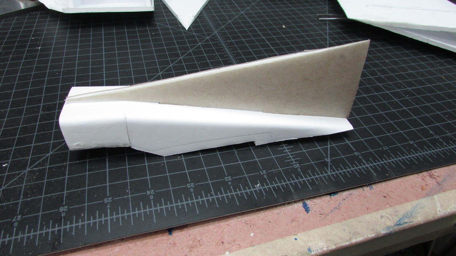
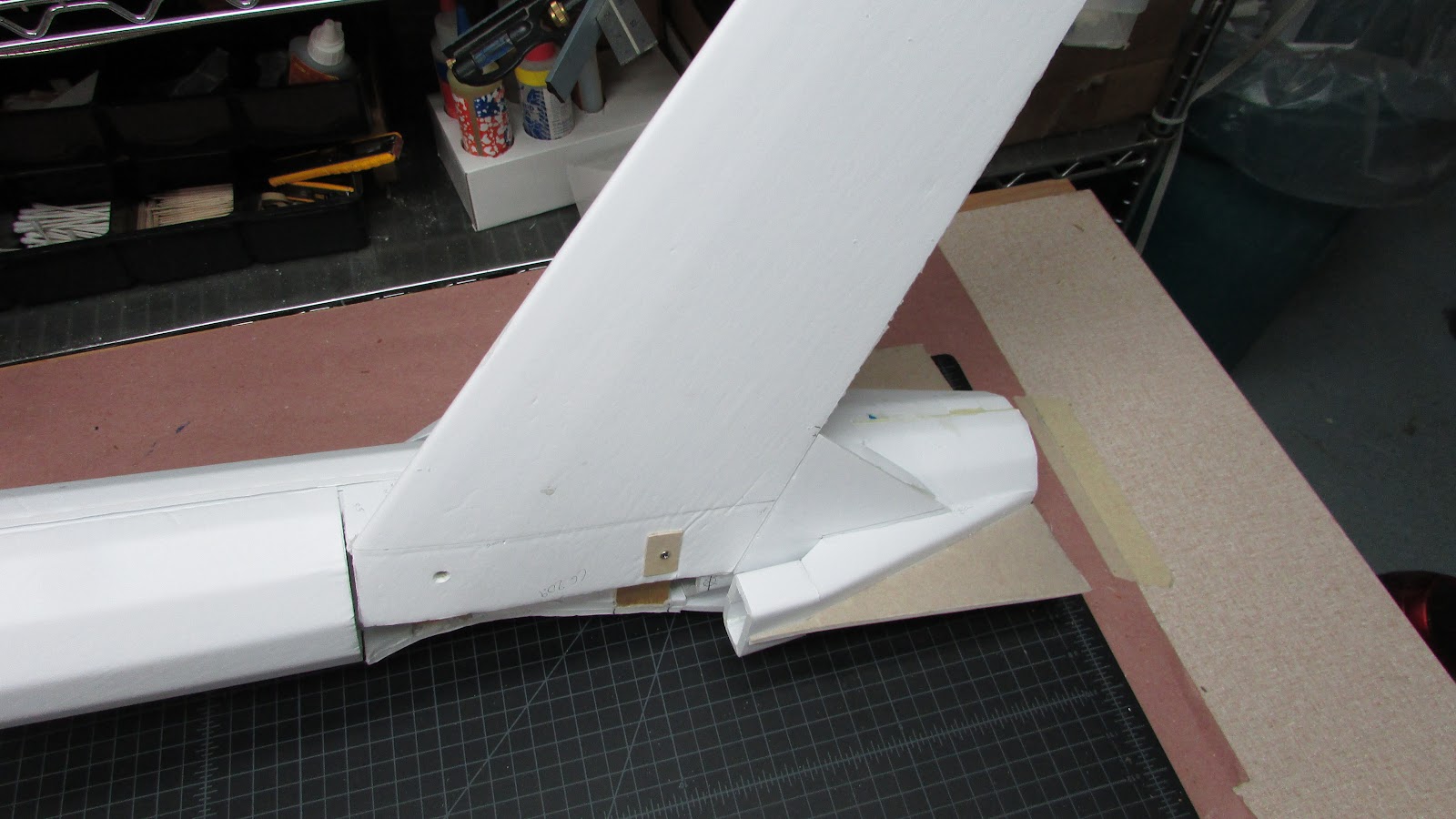
The tail fin is made from two parts, the fin itself and the supercharger scoop.
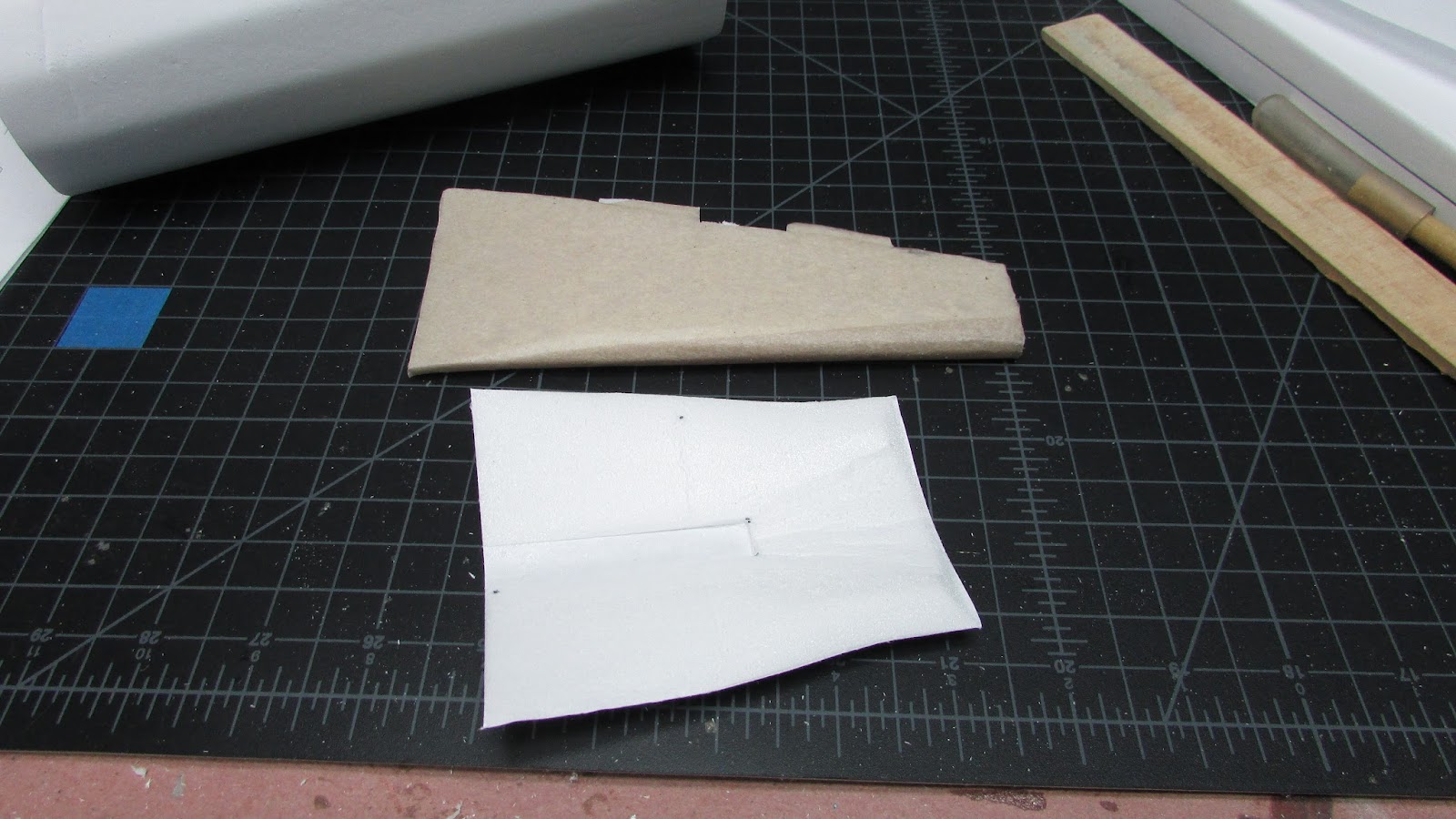
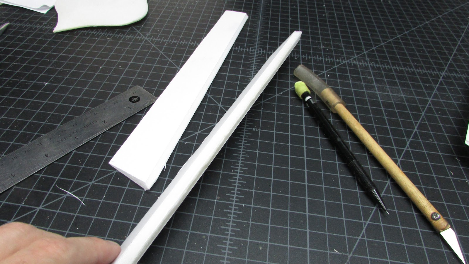
The tail fin is made by gluing two pieces of foam together. The trailing edge is beveled to 5 cm from the edge to the center, the top rounded by sanding. The exposed foam was resurfaced with DuraClear (Polycrylic) and overlaid with packing paper.
The supercharger scoop is a little more complicated because it is sanded to almost half the thickness, beveled 3 cm from rear edge and 1 cm from the leading edge and sides. the front of the scoop is sanded so it makes a nice round curve when folded over.

The supercharger scoop is glued to the tail fin by matching the notch in the foam to the tail and folding it over. I used Gorilla glue to attach the two pieces together and I put weight on it to hold it in place while curing. The longer length give a more gradual taper to the tail.
Next steps: Mount the wings onto the fuselage. Design the lower tail fin and radiator scoop.
The tail fin is made from two parts, the fin itself and the supercharger scoop.
The tail fin is made by gluing two pieces of foam together. The trailing edge is beveled to 5 cm from the edge to the center, the top rounded by sanding. The exposed foam was resurfaced with DuraClear (Polycrylic) and overlaid with packing paper.
The supercharger scoop is a little more complicated because it is sanded to almost half the thickness, beveled 3 cm from rear edge and 1 cm from the leading edge and sides. the front of the scoop is sanded so it makes a nice round curve when folded over.
The supercharger scoop is glued to the tail fin by matching the notch in the foam to the tail and folding it over. I used Gorilla glue to attach the two pieces together and I put weight on it to hold it in place while curing. The longer length give a more gradual taper to the tail.
Next steps: Mount the wings onto the fuselage. Design the lower tail fin and radiator scoop.
HilldaFlyer
Well-known member
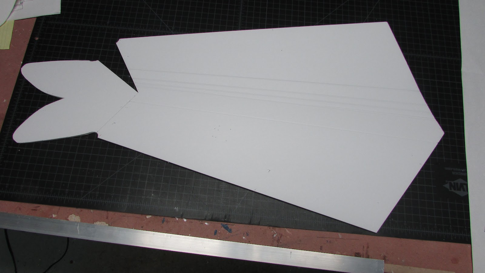
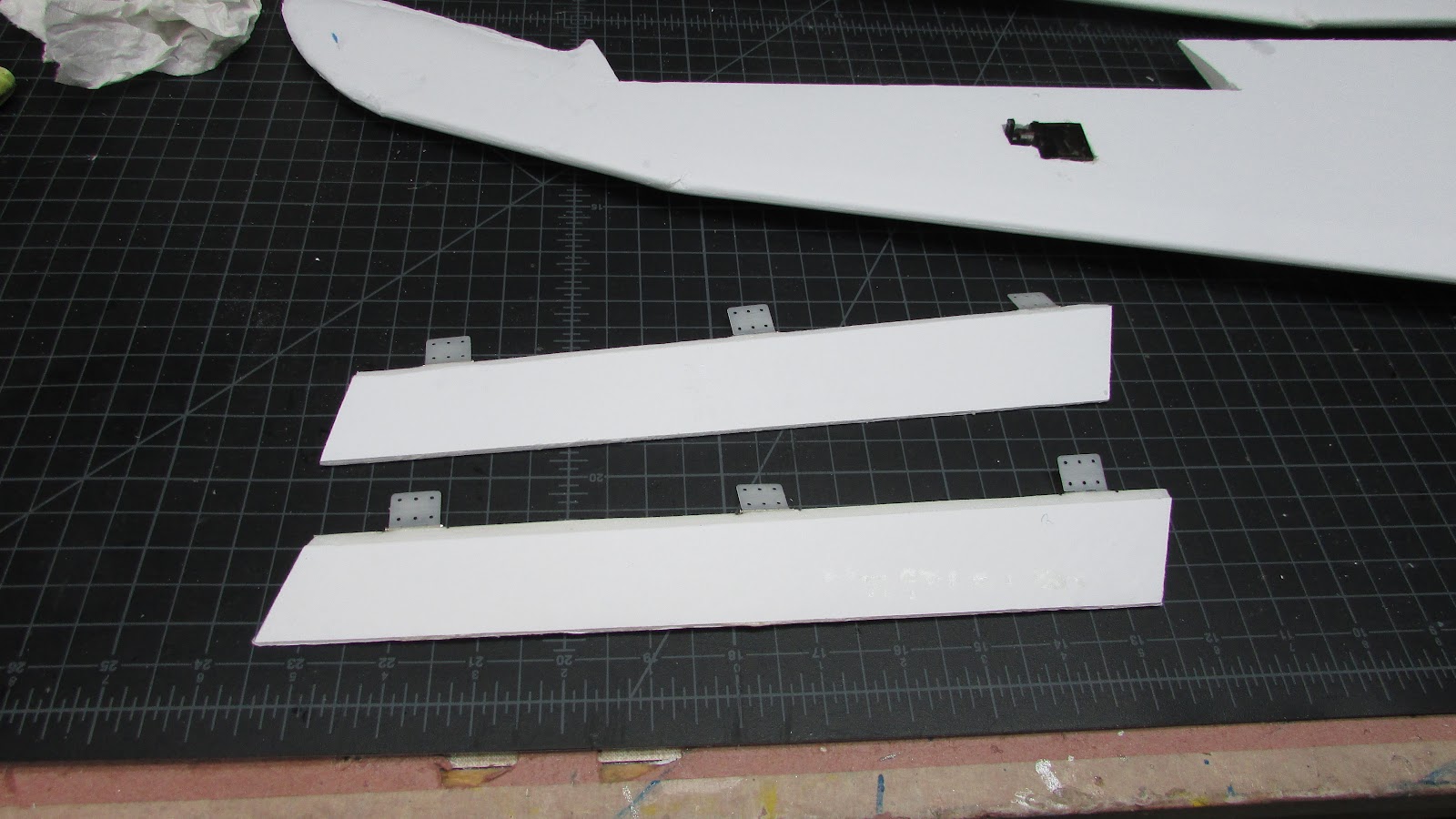
[h=1]Lower Air Scoop[/h]Outline shape
Crease along fold lines.
Bend along fold lines.
Cut out except vertical stabilizer tab holes.
Glue front scoop and hold together with tape.
Glue the crease and hold at proper angle with the wing trailing edge piece.
Cut out vertical stabilizer tab holes
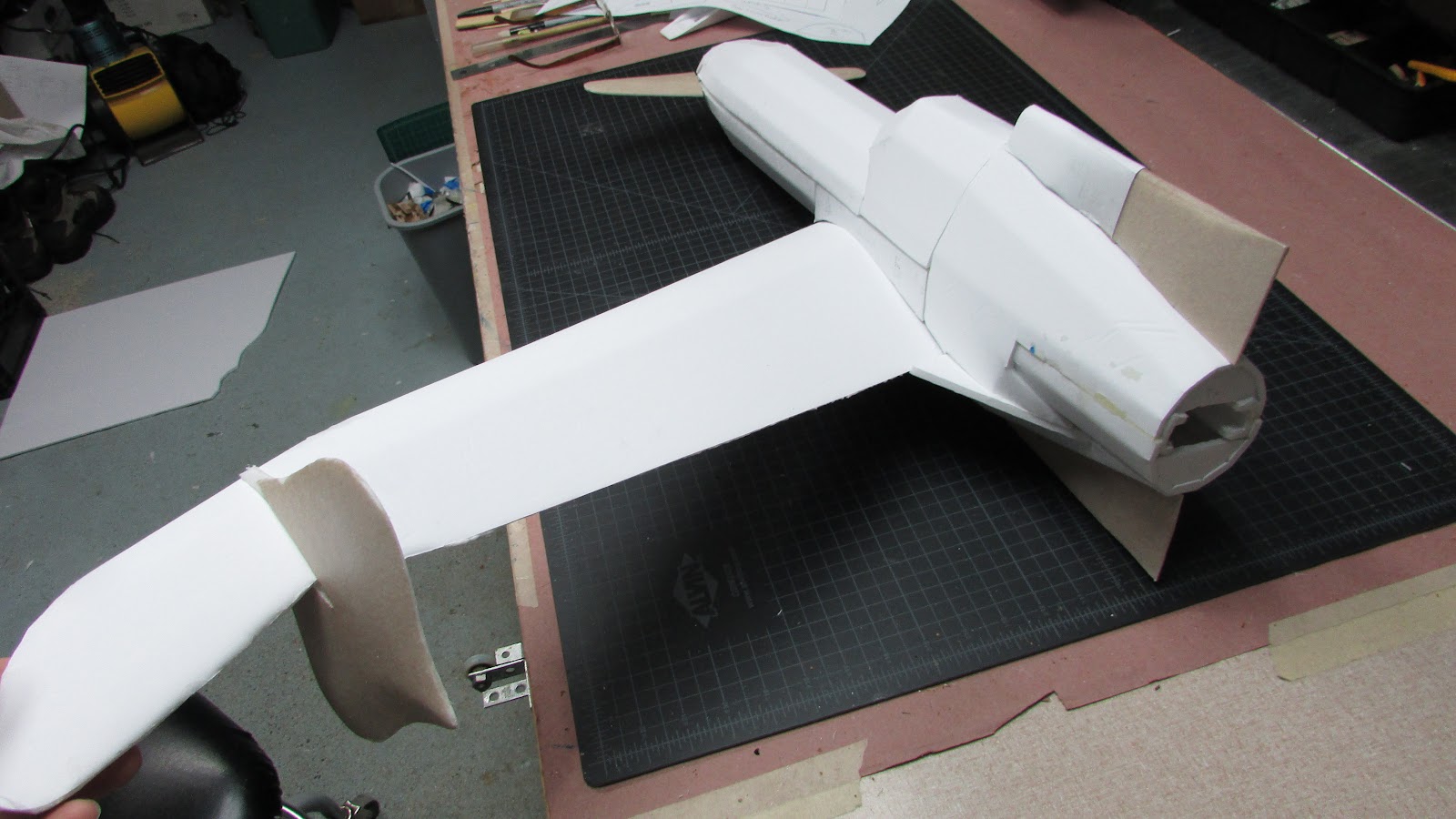
Version 2 of the lower air scoop.
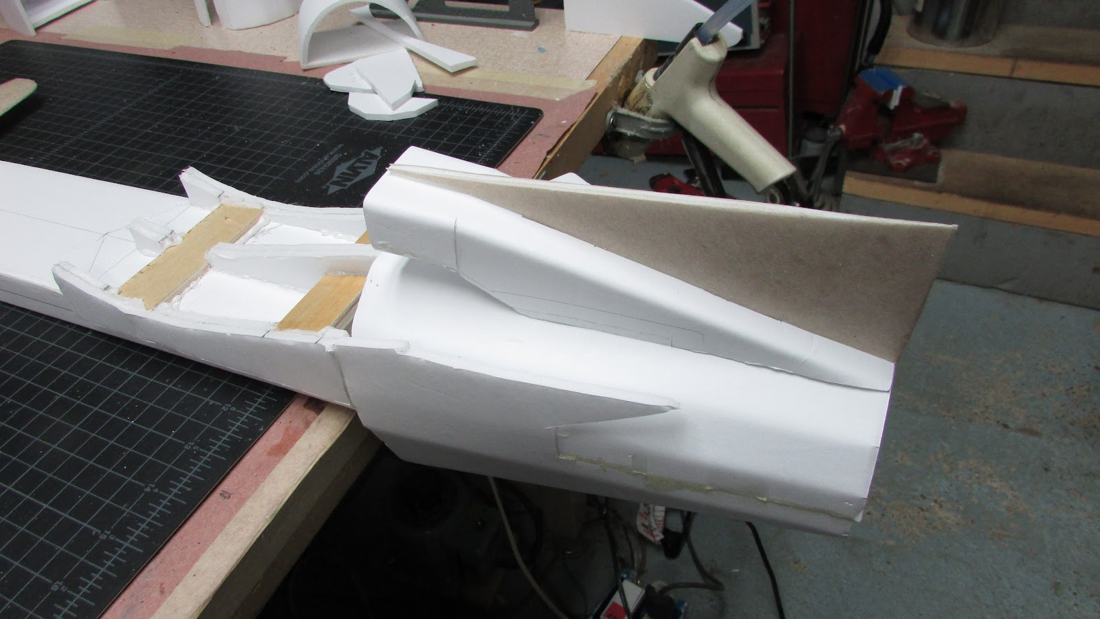
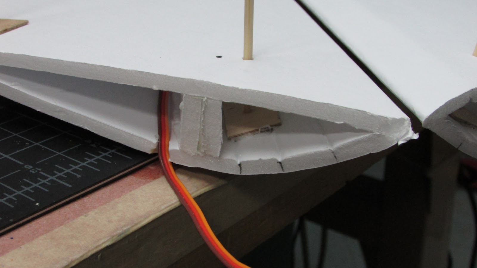
Here is the scoop fitting into place…
I had planned on making this a hand launch belly lander, but this functional motor cooling air scoop may not last. Still thinking about landing gear.
Crease along fold lines.
Bend along fold lines.
Cut out except vertical stabilizer tab holes.
Glue front scoop and hold together with tape.
Glue the crease and hold at proper angle with the wing trailing edge piece.
Cut out vertical stabilizer tab holes
Version 2 of the lower air scoop.
Here is the scoop fitting into place…
I had planned on making this a hand launch belly lander, but this functional motor cooling air scoop may not last. Still thinking about landing gear.
HilldaFlyer
Well-known member
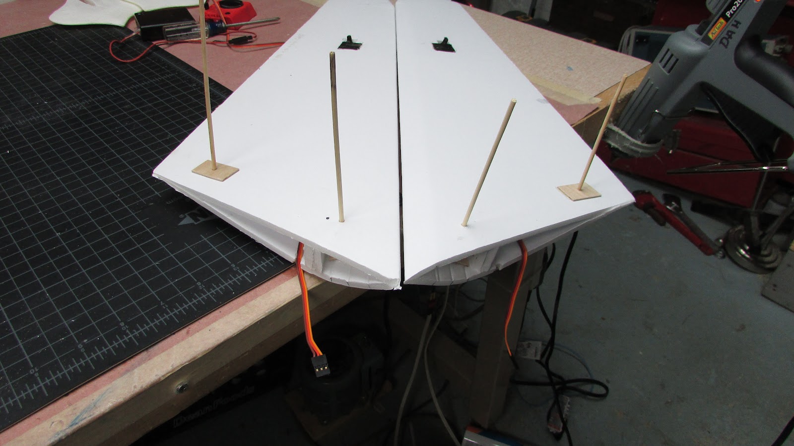
Last night I fitted all the loose pieces I had, and without gluing, took some photos of the plane. I think I'm almost done with the design and ready for the final build. Here are the photos.
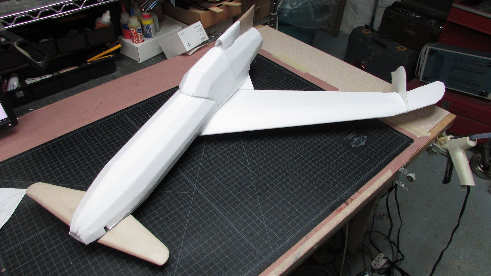
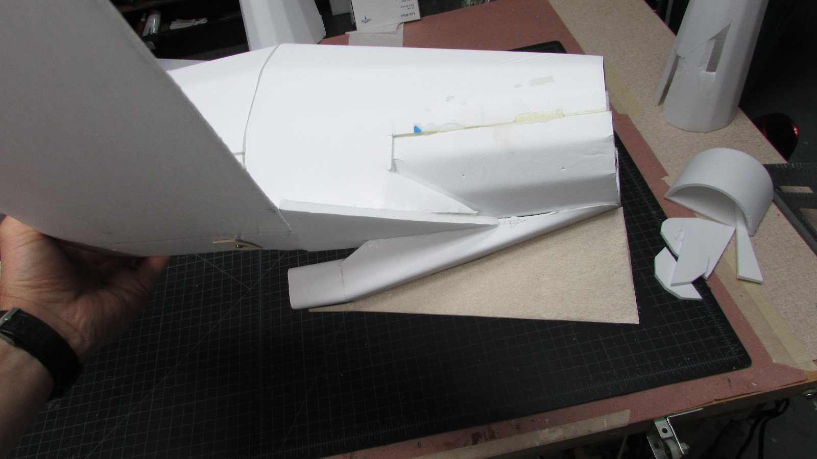
Top view, Nose piece needs to be glued... keeps flexing out of place.
Lower air scoop and wing joint.
Rear side view,
Keep in mind that all these pieces are just sitting in place without glue. The wing, however, is attached with screws.
Sweet!
Top view, Nose piece needs to be glued... keeps flexing out of place.
Lower air scoop and wing joint.
Rear side view,
Keep in mind that all these pieces are just sitting in place without glue. The wing, however, is attached with screws.
Sweet!
F106DeltaDart
Elite member
Awesome work, looks absolutely fantastic!!
HilldaFlyer
Well-known member
Time for another update
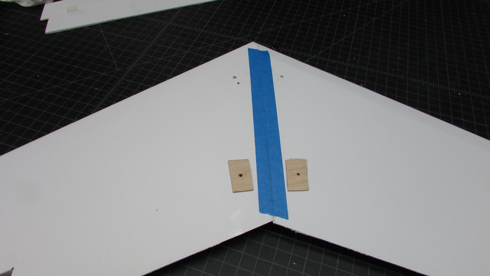
Moved on from the prototype and started to build another set of wings - the real ones.
Changed the wing plans a bit by adding a split top at the tip, this way the tip has a folded over leading edge like the main wing. The split is glued and the vertical stabilizer covers the glue seam.
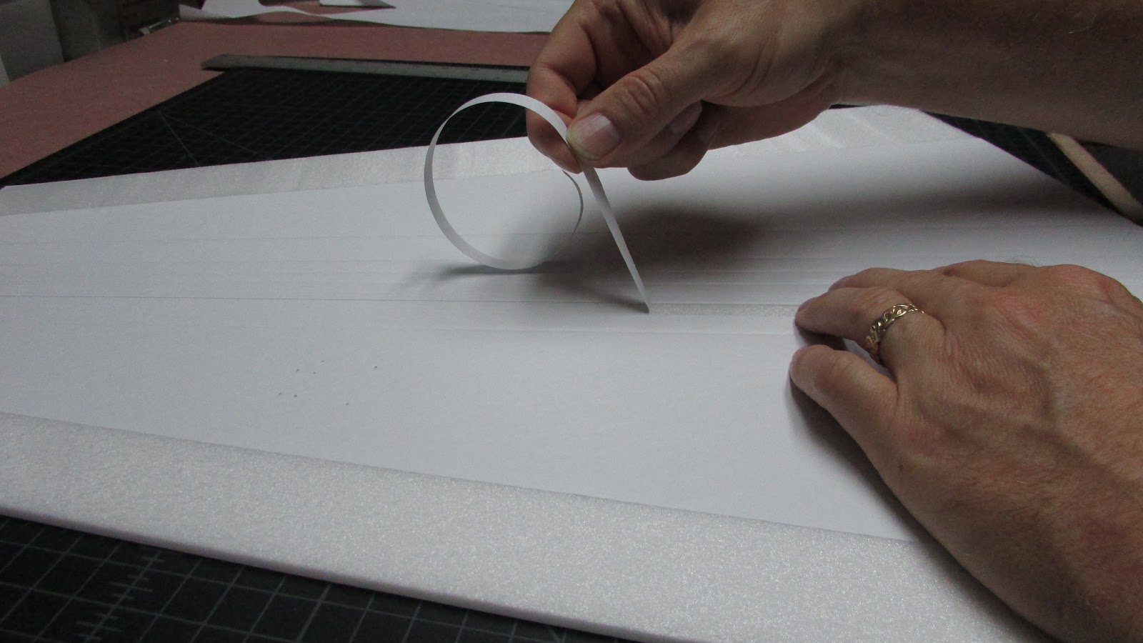
The leading edge bevel was made by peeling the paper to 1 cm from the leading edge. I used a hot wire cutter between the paper fold and the cut. Made a perfect bevel. I made a movie of the process because a video is worth 500,000 words.
The computer with my video editing software decided it was time to come down with a cold during a Windows update. After the update it boots to a screen that looks like windows wants me to restore… but that will be tough because my restore disk didn’t work. Oh, well, Just letting you know that the video will go here when I get it done. I thought the process was really slick - no knife, no sanding, like as smooth as hot wire through foam. Everyone will start doing it this way.
Glued it with Gorilla glue. Didn’t take any pictures, but the main wing was glued first and then the tip was glued, it being held with tape.
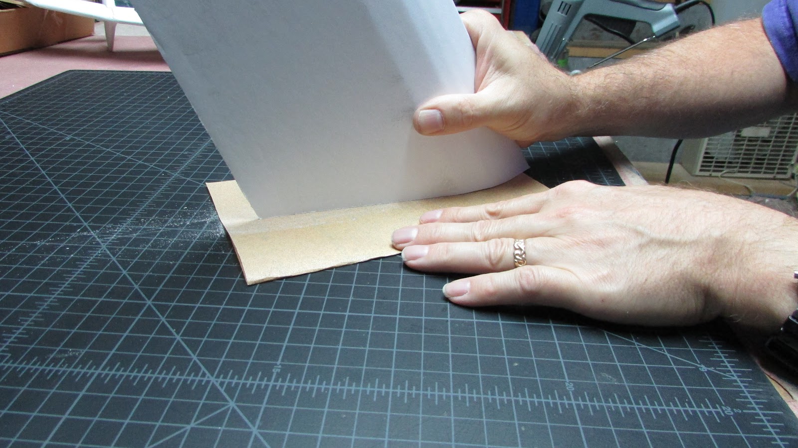
Sanded the root flat.
Cut a hole for the servo.
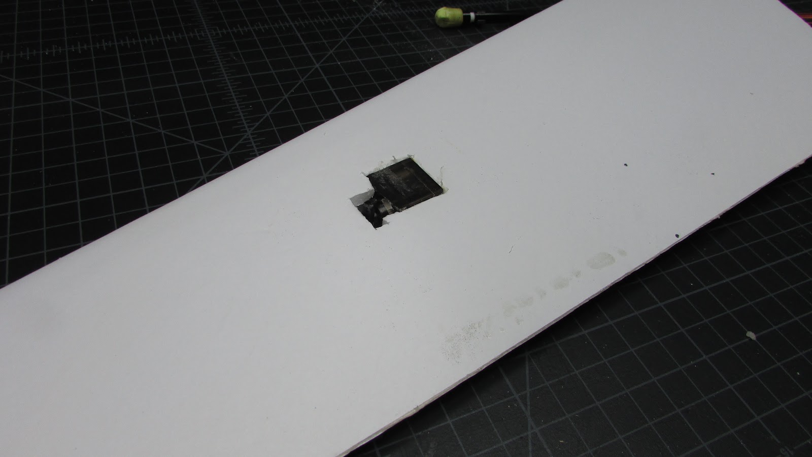
Installed the servo.
Glued pieces of plywood to the wing to give the mounting screws some surface area.
Here is a peek into the root where the plywood was fastened.

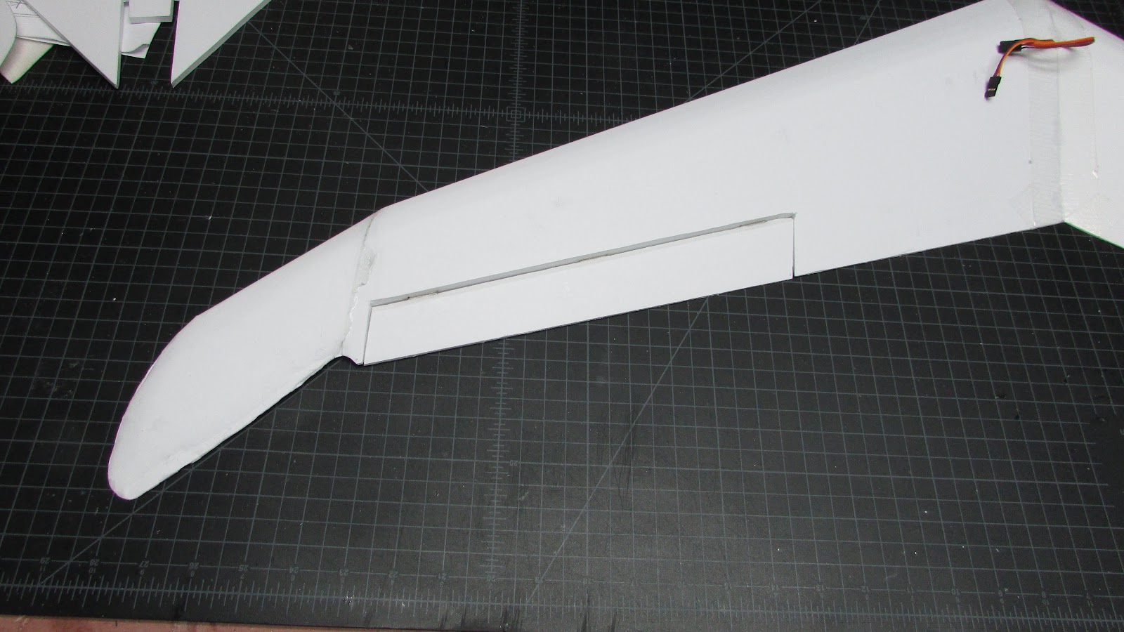
Cut out the aileron.
Made the aileron bevel by removing paper to 5 mm from the front edge and then used a hot wire cutter to remove the foam between the paper and the panel joint. Another video of this?
Cut slots in between the foam and glued in the plastic pin hinges.
Taped the bottom of the wing panels together. Folded the wing open along the tape, Applied Gorilla glue to all mating surfaces.
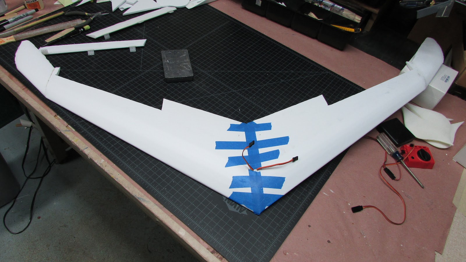
Taped the top to hold the panels together.
Glued the ailerons into the wing.

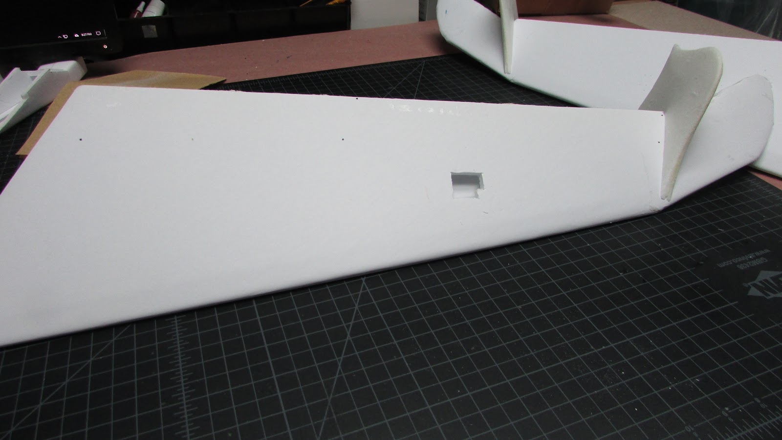
Here is the completed wing. Turned out to be a lot wider than I anticipated.
Moved on from the prototype and started to build another set of wings - the real ones.
Changed the wing plans a bit by adding a split top at the tip, this way the tip has a folded over leading edge like the main wing. The split is glued and the vertical stabilizer covers the glue seam.
The leading edge bevel was made by peeling the paper to 1 cm from the leading edge. I used a hot wire cutter between the paper fold and the cut. Made a perfect bevel. I made a movie of the process because a video is worth 500,000 words.
The computer with my video editing software decided it was time to come down with a cold during a Windows update. After the update it boots to a screen that looks like windows wants me to restore… but that will be tough because my restore disk didn’t work. Oh, well, Just letting you know that the video will go here when I get it done. I thought the process was really slick - no knife, no sanding, like as smooth as hot wire through foam. Everyone will start doing it this way.
Glued it with Gorilla glue. Didn’t take any pictures, but the main wing was glued first and then the tip was glued, it being held with tape.
Sanded the root flat.
Cut a hole for the servo.
Installed the servo.
Glued pieces of plywood to the wing to give the mounting screws some surface area.
Here is a peek into the root where the plywood was fastened.
Cut out the aileron.
Made the aileron bevel by removing paper to 5 mm from the front edge and then used a hot wire cutter to remove the foam between the paper and the panel joint. Another video of this?
Cut slots in between the foam and glued in the plastic pin hinges.
Taped the bottom of the wing panels together. Folded the wing open along the tape, Applied Gorilla glue to all mating surfaces.
Taped the top to hold the panels together.
Glued the ailerons into the wing.
Here is the completed wing. Turned out to be a lot wider than I anticipated.
Last edited:
Michael9865
Elite member
Nice progress.
HilldaFlyer
Well-known member
Yeah, and if my home computer didn't blow out the hard drive, I would have probably have the prototype ready for maiden... but aiming for next Saturday if the weather holds.
HilldaFlyer
Well-known member
Help! Help! Help !!!
If you listen to FreeFall RC podcast... you'll get it.
However, this is a plea for help.
Placing the battery to balance the CG will be a challenge, to say the least.
I’ve got enough of the airframe together to do a preliminary balance act.
First - I’m really excited about how it turned out. Looks really cool.
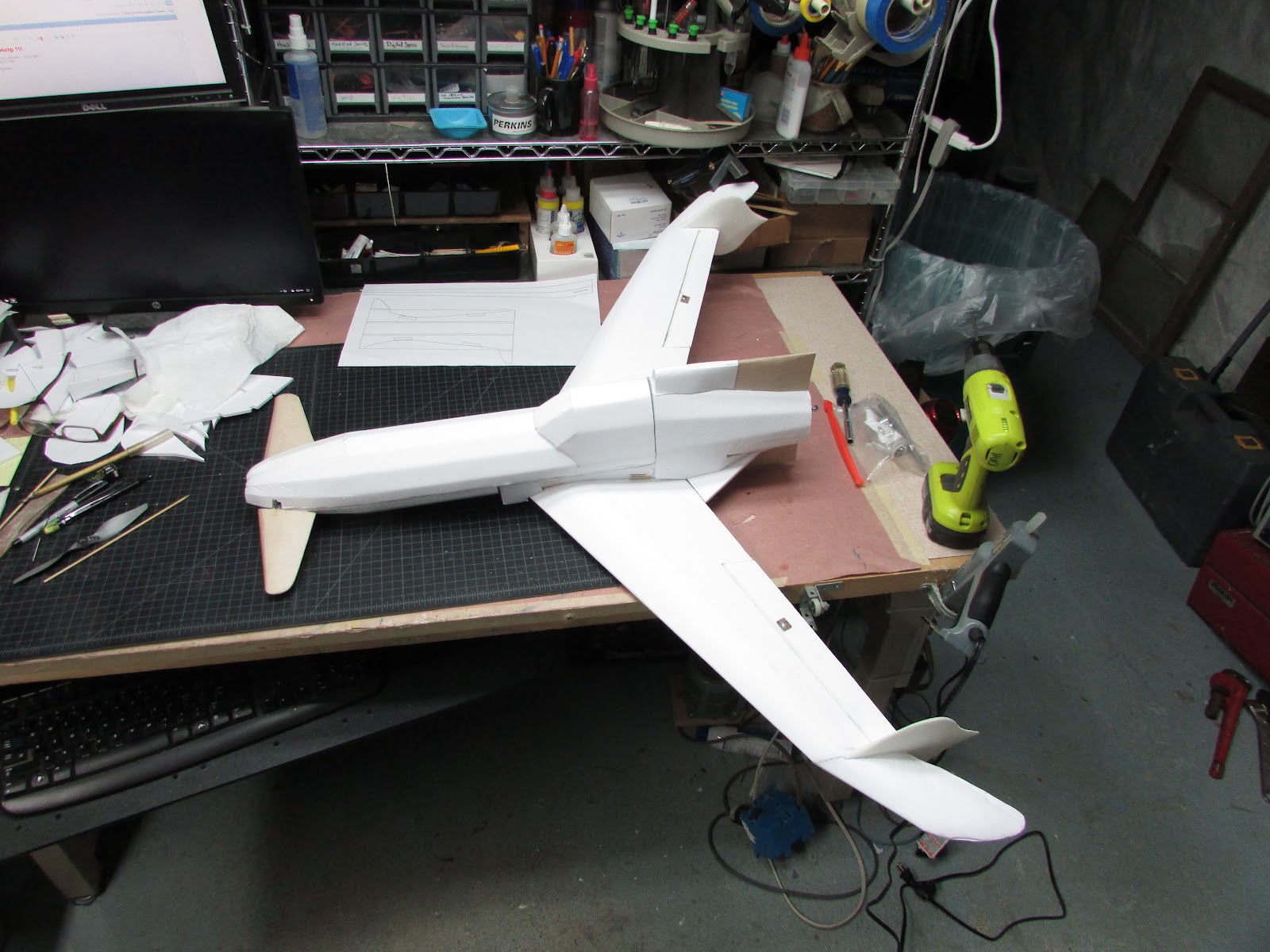
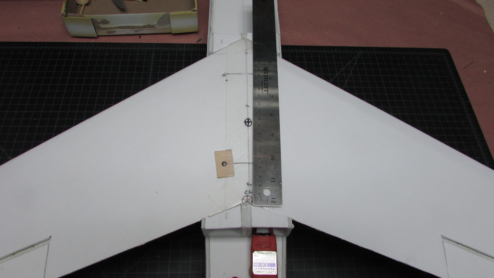
I used the wing CG calculator to determine the location of the CG.
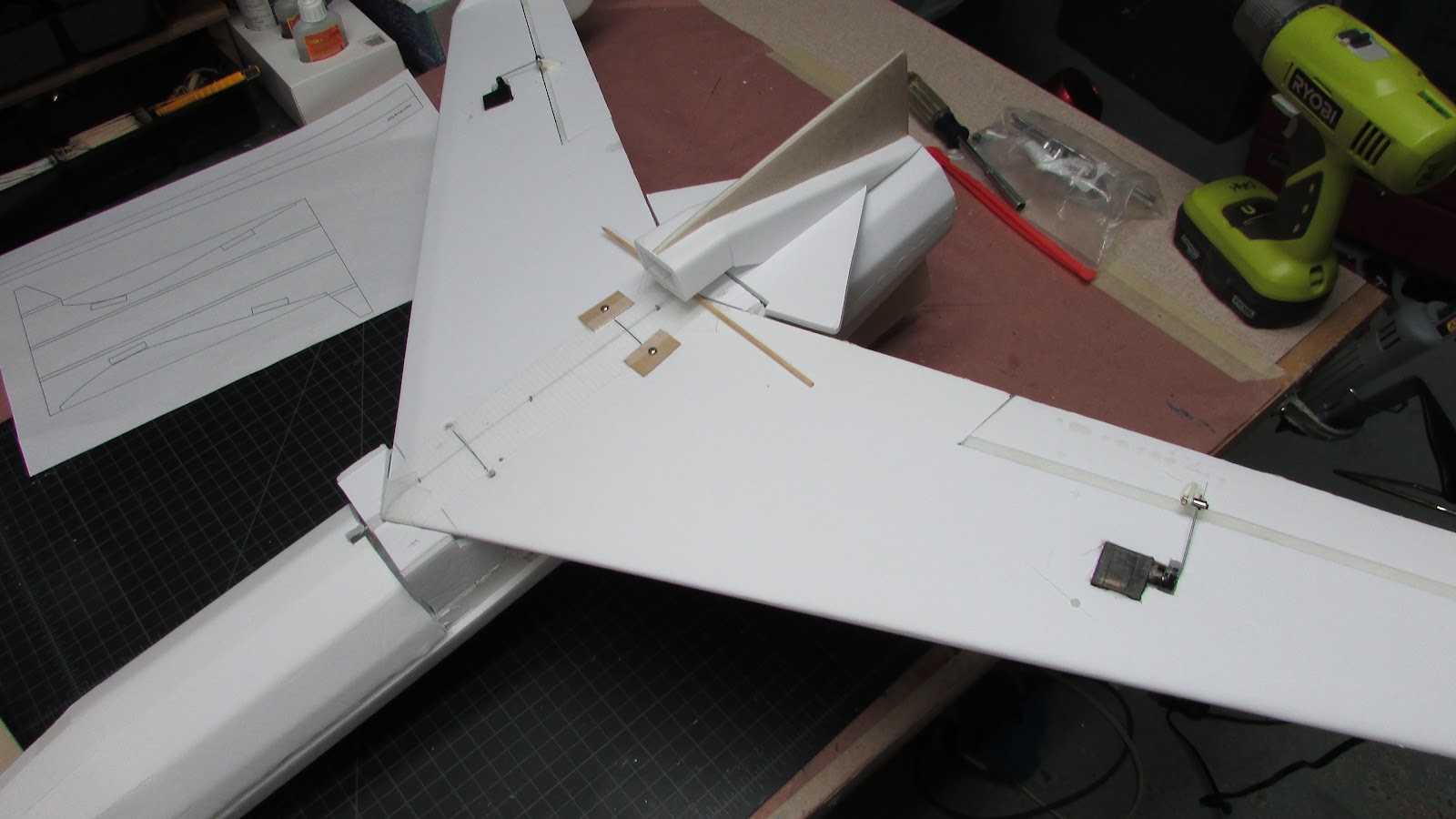
According to the calculator, the CG is located right at the trailing edge of the wing where the roots meet. I’ve laid a skewer at the location. This line is about 1.5 cm in front of the servos.
Here is the problem.
To get it to balance, the battery needs to be placed as far back as the plane will allow.
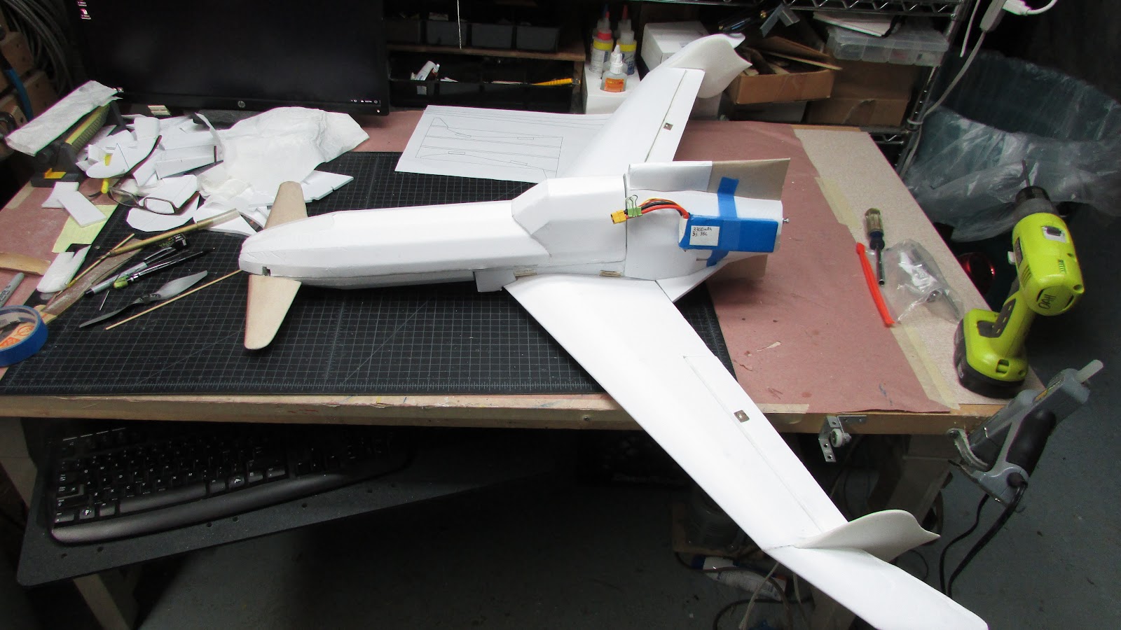
Here is where the battery needs to be placed. Hmmm, there isn’t that much space since the motor is back there. The furthest back the battery can be placed is about 3 cm more forward than pictured above.
Here is where I could use some help.
I have disregarded any lift from the canard arguing that elevators are ignored as lift surfaces. Am I all wet? Can I make this aircraft a bit more nose heavy than calculated based on a flying wing?
I have quickly scoured the internet for information on the CG for this or a Shinden? That information will certainly help - so if you know where I can get it, please let me know. .
Cheers everyone!
Looks like the scheduled maiden for tomorrow will be postponed until I get this figured out.
If it turns out the CG is not actually more forward than I calculated, I'll be moving the wings forward, which will completely kill the scale.
Sacrifices must be made!
If you listen to FreeFall RC podcast... you'll get it.
However, this is a plea for help.
Placing the battery to balance the CG will be a challenge, to say the least.
I’ve got enough of the airframe together to do a preliminary balance act.
First - I’m really excited about how it turned out. Looks really cool.
I used the wing CG calculator to determine the location of the CG.
According to the calculator, the CG is located right at the trailing edge of the wing where the roots meet. I’ve laid a skewer at the location. This line is about 1.5 cm in front of the servos.
Here is the problem.
To get it to balance, the battery needs to be placed as far back as the plane will allow.
Here is where the battery needs to be placed. Hmmm, there isn’t that much space since the motor is back there. The furthest back the battery can be placed is about 3 cm more forward than pictured above.
Here is where I could use some help.
I have disregarded any lift from the canard arguing that elevators are ignored as lift surfaces. Am I all wet? Can I make this aircraft a bit more nose heavy than calculated based on a flying wing?
I have quickly scoured the internet for information on the CG for this or a Shinden? That information will certainly help - so if you know where I can get it, please let me know. .
Cheers everyone!
Looks like the scheduled maiden for tomorrow will be postponed until I get this figured out.
If it turns out the CG is not actually more forward than I calculated, I'll be moving the wings forward, which will completely kill the scale.
Sacrifices must be made!
jpot1
Elite member
After seeing the article on the varieze recently I found some aerofred plans I was looking at. That model seems quite similar to yours and places the CG in front of the rear wing. Take a look. https://aerofred.com/details.php?image_id=91724
Edit: well in looking again maybe not in front but much further forward as compared to yours.
Edit: well in looking again maybe not in front but much further forward as compared to yours.
It looks awesome!
When I did the CG calculations for the FW-42 I just maidened, I did it first with a 5% static margin, and then again with a 15% margin and drew the resulting 3/4" range on the plane. Here are the calcs I used;


After glide testing the best spot was in that range at about 2/3 of the way towards the nose - so maybe a 7% margin. On the maiden flight that turned out to be perfect for very stable performance - I'll probably want to shift the CG back a 1/2" for more aerobatic flight and will test that out this weekend.
The only other thing I can say about the CG is make sure to do glide testing before powered testing. If it doesn't have a smooth trajectory when it's tossed into high grass, adding power won't make things more stable. :black_eyed:
HilldaFlyer
Well-known member
Thanks for you thoughts.
Looking back through the thread, I noticed that I omitted a post on CG calculations. I used the Flying wing:
I was unaware of calculators for different style aircraft... so I'm digging into that.
Here is what I wrote in my build log:
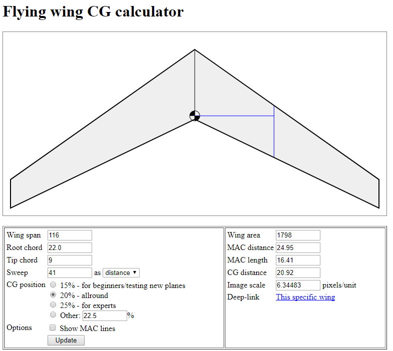
The CG calculator puts the CG right at the convergence of the trailing edges. At first thought, this plane is going to be hard to balance since it has such a long fuselage in front of the CG.
-----
And I was right.
Looking back through the thread, I noticed that I omitted a post on CG calculations. I used the Flying wing:
I was unaware of calculators for different style aircraft... so I'm digging into that.
Here is what I wrote in my build log:
The CG calculator puts the CG right at the convergence of the trailing edges. At first thought, this plane is going to be hard to balance since it has such a long fuselage in front of the CG.
-----
And I was right.
HilldaFlyer
Well-known member
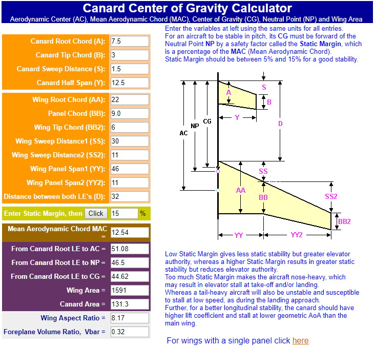
Here are the new calculations - Thanks Rockyboy!
Rockyboy provided a link to a really great CG calculator
Rockyboy provided a link to a really great CG calculator
HilldaFlyer
Well-known member
This calculator moves CG 9.5 cm forward.
Certainly a lot easier to balance there. I'm a bit skeptical, but I don't have anything better to gamble on. My simple calculation was for a wing only. So - I trust more in the calculator that takes the canard and wing tips into consideration.
But now... for the real test.
But first, Now I have to relocate the battery to the spot where the receiver was placed. Reconfig
Last edited:
HilldaFlyer
Well-known member
Maiden - Success !!!
Video - Coming Soon
I'll just say that the CG was different than either calculator. The calculator that took the canard into consideration was closest. To get a good flight I ended up moving the battery rearward about 4 cm.
Video - Coming Soon
I'll just say that the CG was different than either calculator. The calculator that took the canard into consideration was closest. To get a good flight I ended up moving the battery rearward about 4 cm.
Similar threads
- Replies
- 53
- Views
- 8K
- Replies
- 52
- Views
- 4K
- Replies
- 36
- Views
- 6K
- Replies
- 4
- Views
- 4K
- Replies
- 36
- Views
- 5K