Hildaflyer,
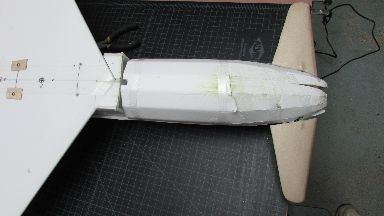
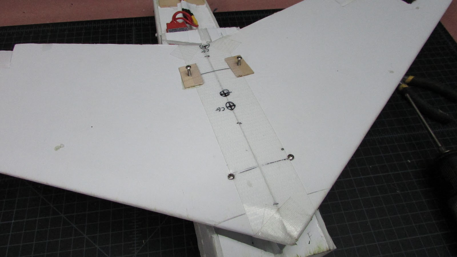
You asked for this info on facebook after I referenced it and then found out that the plans I directed you to don't actually list the CG. So here's the skinny: for a free flight model of the XP-55, the CG goes at or slightly ahead of the wing root leading edge. This actually from three different people who have gotten these to fly, including a retired AeroVironment designer, so I reckon it's pretty authoritative advice..
Thanks! And I agree that is probably good advice. All I have to say is mine is nowhere close. Mine is aft, more near the trailing edge. Which begs the question why? So, What is the difference between a free flight plane and a powered plane? Nothing, I hope, as far as CG is concerned, right?
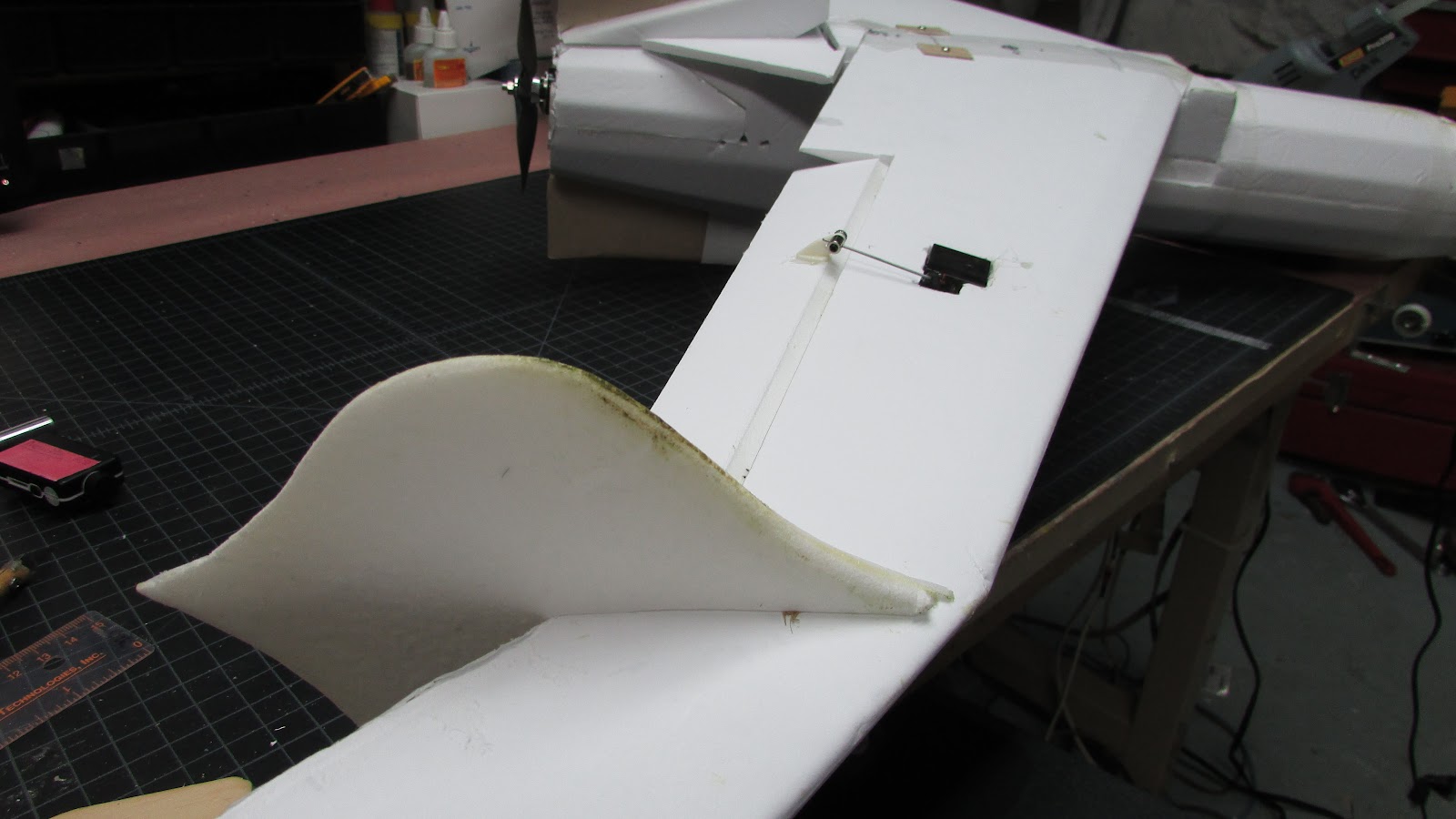
I'd tack onto that the prediction that you'll need about 10 degrees up trim in the canard to maintain level flight, so make sure you have enough travel to accommodate that if you also want to be able to do inverted (if it's stable, it'll do inverted
")
).
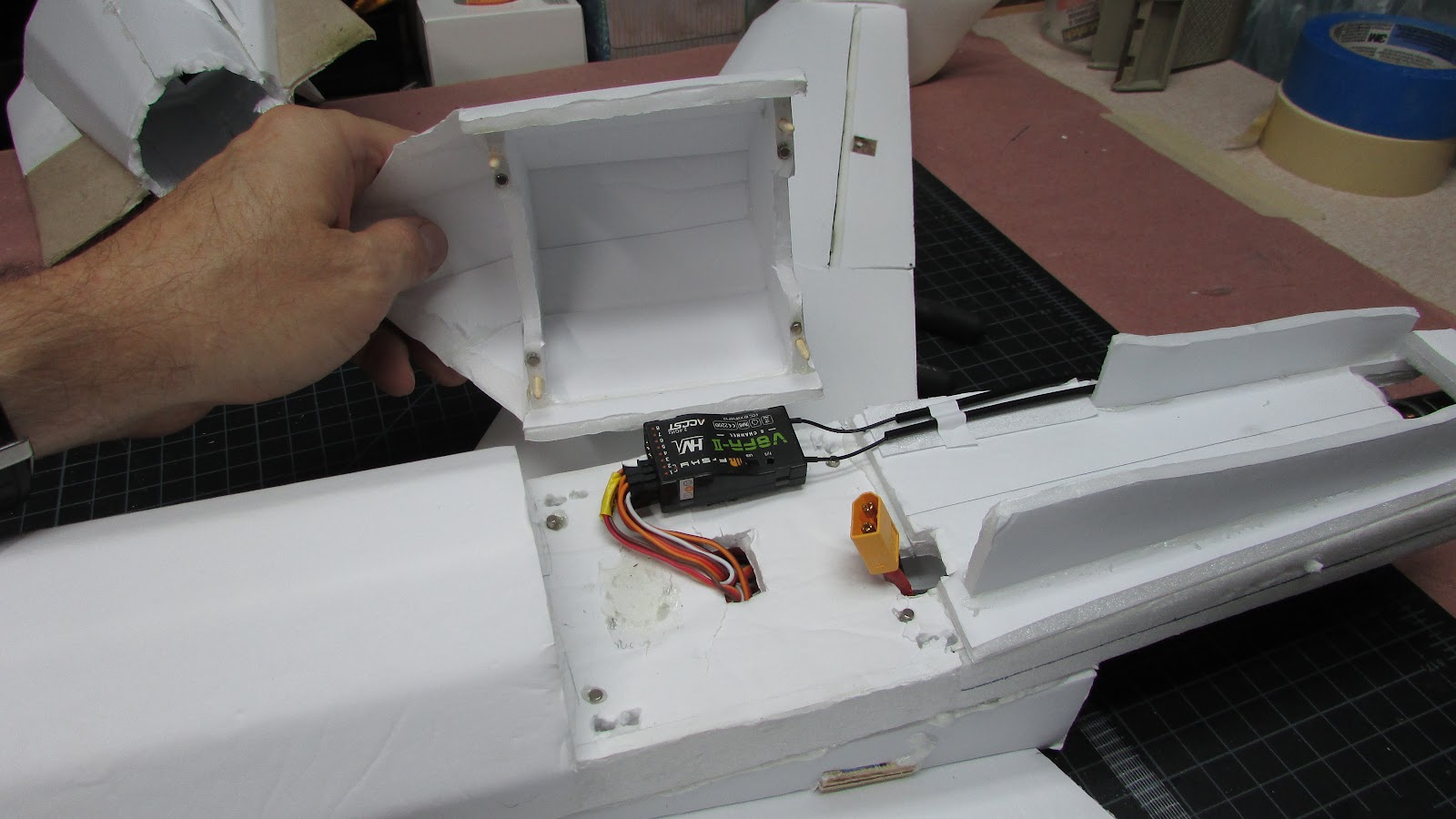
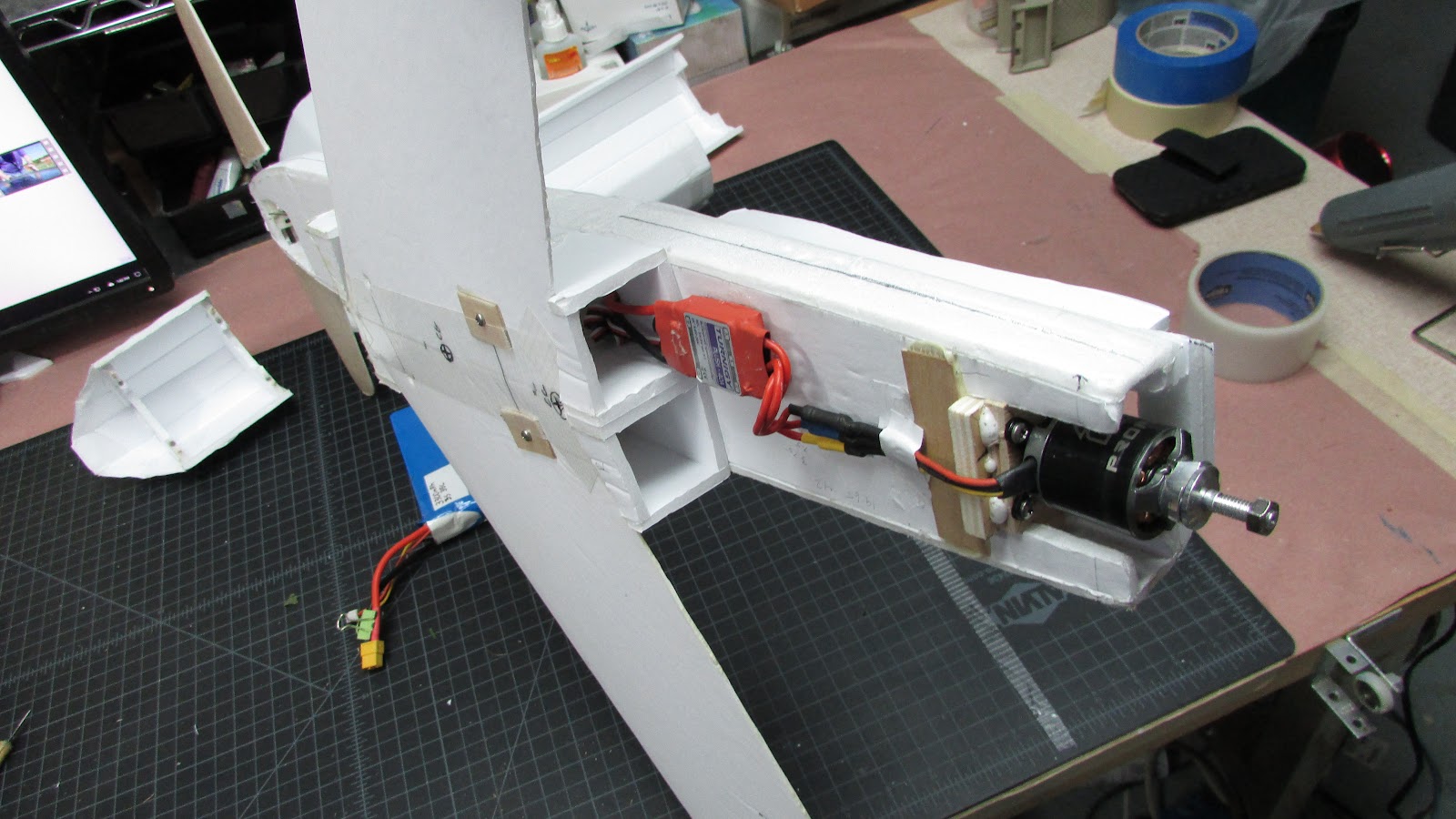
Wow, that much? Currently I have 1 to 2 degree up trim on the canard. I did have it a zero until moments before the maiden. I've got lots of throw to play with, probably 40 degrees (I'll take some more photos).
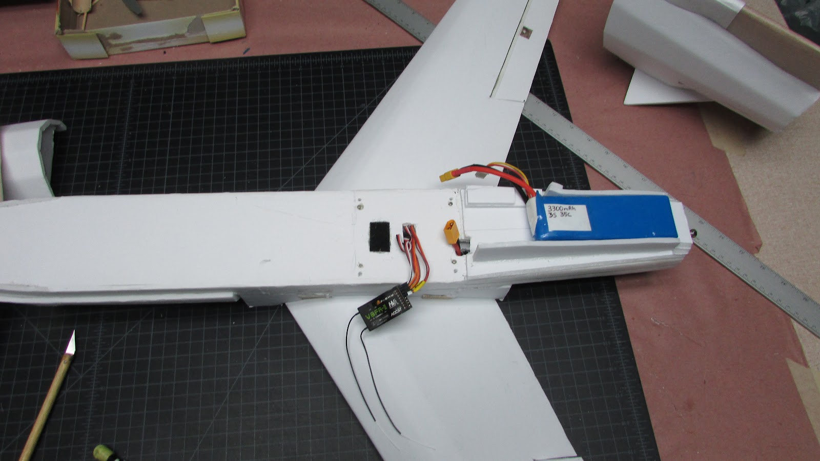
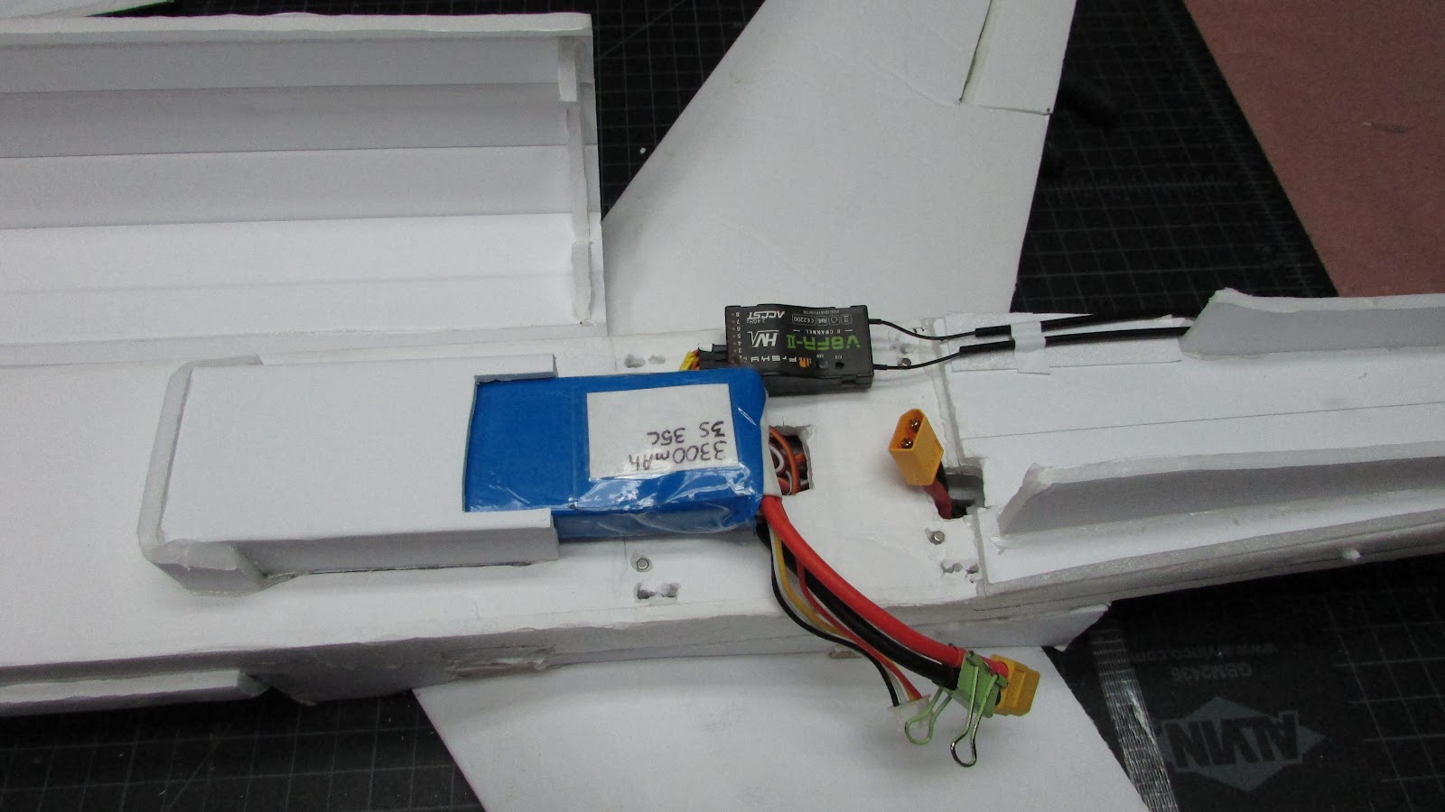
During the first flight, after getting the roll straightened out was full up and it still went into the grass. So I doubt very much that I'll move the CG more forward. My plan was to leave everything as is, do a series of flights and move the battery a bit more forward on each flight and monitor the characteristics. Can't argue with a good flying plane. I'll get it there.