Problems Communicating with Witespy aka Paul Baxter aka RTF Quads

Mastrmindz

New member
Hey FT.

I have a problem and I am hoping you can help me out. (I am not sure this is the right forum topic for this issue, but it is slightly related to customer support).

I have been in the hobby for a few months now. Back in late May, I had to replace my KK 2.1 board and decided to go with the Flip 1.5 board from RTF Quads under the recommendation of the Flite Test team and many others on the interwebs. I got the board in June and was really excited to install it on my Rotorbones tricopter. Everything worked except the tail servo.

After roaming the forums, I found that the general consensus was that not enough power was delivered to the servo from the FC. I tried to get in contact with Witespy and he eventually replied. After a few emails back and forth, he said that he would send me some schematics for the power distribution involving a UBEC. After a few months, I still not have received that schematic. I have sent him multiple emails and have not heard back from him.

I am very disappointed in the product so far. I have tried everything to get the tail servo working and tried connecting the UBEC in multiple ways, burning out several servos in the process. I had a friend come and look at it and he said that there might be something wrong with the code. I would not understand why that would be the case since I ordered mine flashed for a tricopter.

Since you, the FT team, are personal friends with Paul Baxter and are working with him on a few projects, I am hoping you can help me with a solution to this problem. I mainly bought the Flip 1.5 because of your suggestion. I do not want to fully discredit RTF Quads' products. I seem to be one of only a few people to have this problem. If you can help me get in contact with Paul or recommend another one of his products that will for sure work with my tricopter and is still under that $40 price range, I would really appreciate it.

Thanks!

Mastrmindz

P.S. Your show is the BOMB! Love it!
 
Last edited:

bacpck

Senior Member
I am sure someone will be along to help shortly.

With the separate UBEC how did you try and wire it up? If you are using a common ground I would believe you just need the power wire from the UBEC to go to the power wire on the servo but I could be wrong. I have never attempted to wire up a servo that way.

However I do use a separate UBEC to power my board and servo on my Tri (using the KK2.1) but the servo is still getting it's power through the KK2.
 

Balu

Lurker
Staff member
Admin
Moderator
Mastermindz, Paul is a little (understatement) overwhelmed with work and is known to be a little slow with delivering and communication in the last few weeks/months.

You might want to ask your question in the electric multirotor section of this forum. People are usually a lot faster with suggestions.

If you think it's something with the software, you could try and flash the flip yourself. The code should be available on the RTF website. I have no flip, so I don't know what tools you need to do that.
 

bacpck

Senior Member
The whole package of sketches (flash for certain multirotor) and all of the interface software is available via links on Paul's website.

https://www.youtube.com/watch?v=iry4vaE4RUY&list=UUHPnC8onfzmaBnm4487kyew

Is a great video by Crash on the 1.5 setup GUI etc. It is a bit long but you will have a much better understanding after watching it. I just recently got some 1.5's but have had very little chance to play with them yet. I did get them working and talking with my computer but am a long way off from sticking them on a airframe.
 

Mastrmindz

New member
I am sure someone will be along to help shortly.

With the separate UBEC how did you try and wire it up? If you are using a common ground I would believe you just need the power wire from the UBEC to go to the power wire on the servo but I could be wrong. I have never attempted to wire up a servo that way.

However I do use a separate UBEC to power my board and servo on my Tri (using the KK2.1) but the servo is still getting it's power through the KK2.

Hey bacpk. Thanks for the reply.

I tried wiring the power and ground from the ubec to the power of the servo. I did that using the mail connections in a Y-splitter. I also sent the signal of the servo to the FC. It seemed to get the power, but not the signal.

And yeah. That video was really helpful in the set up. I still had trouble looking for any problem in the code. Thanks for the help.

Mastrmindz
 

Mastrmindz

New member
Mastermindz, Paul is a little (understatement) overwhelmed with work and is known to be a little slow with delivering and communication in the last few weeks/months.

You might want to ask your question in the electric multirotor section of this forum. People are usually a lot faster with suggestions.

If you think it's something with the software, you could try and flash the flip yourself. The code should be available on the RTF website. I have no flip, so I don't know what tools you need to do that.

Hey Balu. Thanks for the reply.

Yeah. I figured as much. However it is still a little annoying. He kind of left me hanging mid-email-conversation. I was hoping if I posted in this section of the forums that I would grab someone's attention in FT HQ. I will try to post this in the electric multirotor section, though.

I also have tried looking at the code. Although it is pretty massive, I had trouble determining the problem with the servo. The code states for the servo to move to three positions when arming. Mine does it initially, but then does not move at all when giving input. The gui showed the FC receiving the rudder signal, but no activity in the servo.

I will see what the other forum section has to say. Thanks.

Mastrmindz
 

bacpck

Senior Member
Mastermindz.. i will probably run into Paul tonight on the live portion of a podcast this evening. I will try and point him over to this thread and see if I can help. I know he is extremely busy and trying to do his best. I will at least throw the info at him.
 

Mastrmindz

New member
Mastermindz.. i will probably run into Paul tonight on the live portion of a podcast this evening. I will try and point him over to this thread and see if I can help. I know he is extremely busy and trying to do his best. I will at least throw the info at him.

WOW! That would be fantastic! Thanks so much. I really appreciate it.

Mastrmindz
 

bacpck

Senior Member
also found this. I am assuming that you are only powering the board from one source.

"
1.- with the tail (or yaw) ESC, I powered the tail (or yaw) servo, nothing else. Just the signal wire from this ESC is connected to the Flight Controler (Witespy MultiWii Pro 2.0 in my case). Positive and gnd goes to tail servo.
2.- with the front-right ESC, I powered the FC and the radio reciever. Of course the ESC is conected to the flight controler.
3.- the front-left ESC has the middle (positive BESC) and gnd wires loose, only the signal wire is connected to the FC."

I
 

bacpck

Senior Member
Also on this page near the bottom in the more how to, there is a photo of a ubec powering a servo directly using a 2.0 multiwii board.

title is "Power a sevro for Tricopter - picture - clips suppy 5 volts "

http://witespyquad.gostorego.com/videos.html

It appears to be a photobucket picture but it will only open in IE explorer and there was a strange pop up last night so I won't directly link to it.

LOL I want to help you get it up and running because I want to convert my BatBone over to a flip/multiwii at some point.

Have you hooked the board up to your computer to confirm the sketch? The USB cord is the same as the new standard for Droid/Google/etc. (not IPHONE) phone cord. I would confirm the sketch and all of the settings.
 
Last edited:

Mastrmindz

New member
also found this. I am assuming that you are only powering the board from one source.

"
1.- with the tail (or yaw) ESC, I powered the tail (or yaw) servo, nothing else. Just the signal wire from this ESC is connected to the Flight Controler (Witespy MultiWii Pro 2.0 in my case). Positive and gnd goes to tail servo.
2.- with the front-right ESC, I powered the FC and the radio reciever. Of course the ESC is conected to the flight controler.
3.- the front-left ESC has the middle (positive BESC) and gnd wires loose, only the signal wire is connected to the FC."

I

Thanks bacpck. The only question I have is how would you connect ESC to the tail servo's power and ground? Do you need a male-male connector?

And yes. I have hooked up the Flip to the computer with a micro-usb cable. There are two Gui's used and they are both really neat to use. I used it to test the signal from Tx to Rx for yaw.
 
Last edited:

bacpck

Senior Member
you can pull the pins out of servo leads so you would need power and ground coming from UBEC going to server and the signal wire from the flight board to the servo... I did this provide power to my FC board through a seperate UBEC.
 

rcflyer729

fpv and rc planes
I have 3 flip boards and they all don't work. 2 of them worked for a time but do not any more and the other one never worked.
 

Mastrmindz

New member
you can pull the pins out of servo leads so you would need power and ground coming from UBEC going to server and the signal wire from the flight board to the servo... I did this provide power to my FC board through a seperate UBEC.

I am a little bit confused. Both the servo and UBEC use female servo connectors. Would I have to take the ground and power pins from the FC and use them to connect the UBEC and servo?
 

bacpck

Senior Member
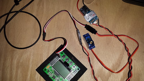
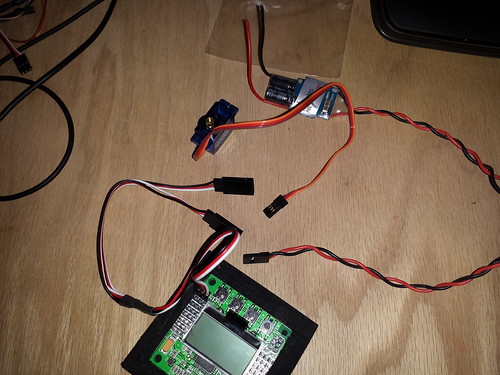
I would buy or make something like this. The Ubec is sending power down the line to the servo directly and it has power going to the FC board. However on this board it can not be powered this way as M2-M8 are isolated and only used to power servos. I could pull the positve and negative pins from the male attachement on the FC board and take them to the M1 terminals to power the board.

20140905_214214


2014-09-05_09-52-28
 

bacpck

Senior Member
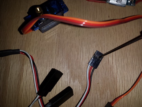
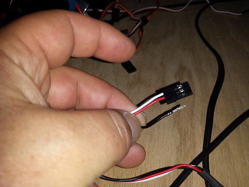
In case you were wondering about pulling the pins.. there is a little tab right at the screwdriver in the first picture. If you lift that and push the wire in then pull it out it will come out and you can put it in another lead or swap to another connector.

2014-09-05_10-07-16


2014-09-05_10-10-13
 
Last edited:

bacpck

Senior Member
You need to be careful and make sure you are putting all the connectors on and in the right places so ground, power and signal are all going to the proper places.

I also wish I knew the power set up on the Flip board.. I don't know it yet but I will be learning soon. Hope this helps.

You do want to make sure you are powering your Flight Controller and Receiver (combo) from only one source. You can provide power to your FC/Rx combo from the M1 ESC (or however you are currently providing power to the board) and use the separate UBEC to power the servo, or you can choose to power the FC/Rx combo and the servo from the UBEC.
 
Last edited:

Mastrmindz

New member
I would buy or make something like this. The Ubec is sending power down the line to the servo directly and it has power going to the FC board. However on this board it can not be powered this way as M2-M8 are isolated and only used to power servos. I could pull the positve and negative pins from the male attachement on the FC board and take them to the M1 terminals to power the board.

20140905_214214


2014-09-05_09-52-28

With the image with the y-splitter and the servo and ubec, are you suggesting that the y splitter just be plugged in to which ever port is designated for the servo? Will that power both the servo and the FC? And will I also have to take the positive and negative from one of the ESC's and plug them into the Rx?
 

bacpck

Senior Member
Yes in my example above you would put it on the pins for the Servo on the FC board. I am not sure if it will power the FC board or not because I am not yet familiar with the Flip power layout. In the example above for a Tri i would remove the positive and negative going the the FC board(on the servo spot, the servo is getting its power directly from the UBEC) and then take them to the M1 or receiver to power it and the FC board.

In my example above it would not power the FC board unless i took the power and ground (currently plugged into the FC board) wire and moved them to different pins but that is because the KK2.1 does not power the board on Motor pins M2-M8.