Archimedian
Member
All up weight- 405 grams
Wingspan- 36 inches
This will be brief. Please leave any questions, tips, or builds of your own in the comments.

Most of the wing construction i will skip. It is a standard D tube wing. The ribs were made using the "sandwich between plywood ribs" method. It was all built as one wing on a pre joined spar of balsa. ALOT of washout was included, and therefore alot of positive incidence was used when placing the wing in the saddle. A single servo in the middle swings pushrods that attach to clevis joints on the internal part of the landing gear wire. Dual aileron servos are used with a Y connector.

These shock absorbers are my baby in this build. They are composed of two different diameter aluminum tubes. The larger tube becomes the moving element. The bottom segment is split open and separated to accomodate a simple paper wheel. A stopper is glued in place at the termination of the split. The spring is then "dropped' in and it rests on this stopper. The narrower tube is completely filled with lightened epoxy, and then cut to accomodate the centering pin. These are much simpler than oleo struts, however, some play occurs in rotation, due to the holes being larger than the pin i used. The entire assembly is epoxied to the remaining wire extending from the already installed retract mechanism.

Fuse is simple enough. 1/16th balsa is laminated to a 1/4inch sheet of pink foam that has been cut to thickness on a table saw. Pink foam blocking inside makes for very quick fabrication compared to bulkheads and stringers. A small magnet is embedded in the "pilot headrest" area to lock in the eventual canopy (which is shaped from a large piece of pink foam) The nose cone is also made of assembled sheets of pink foam, sanded to shape. This makes the inclusion of a cooling duct very easy.
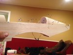
The rudder/stab is made of more pink foam sheet, with a balsa "u" shape accomodating plastic tubes that will accept the centering pins. The rudder can be removed by lifting it straight up after assembly.
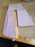
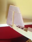
The elevator uses a tape hinge, whcih was extremely lazy considering i used a nice pinned hinge for both the rudder and ailerons. It began by laminating strips of balsa and foam, shaping, and then cutting them apart and cutting a bevel on the table saw. The aerobalance segments were cut out/ glued back on to the moving portion of the elevator. A metal wire strengthens the connection between left and right elevator sections.
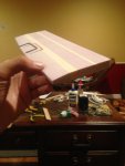

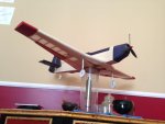
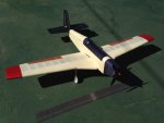
Colored tissue hides my pink foam. The red segments of wingtip are also of pink foam, and were added when i found out how much this thing was gonna weigh. This explains the fairly inboard placement of the ailerons.
Thats it. Maiden this week. Tips appreciated.
Wingspan- 36 inches
This will be brief. Please leave any questions, tips, or builds of your own in the comments.

Most of the wing construction i will skip. It is a standard D tube wing. The ribs were made using the "sandwich between plywood ribs" method. It was all built as one wing on a pre joined spar of balsa. ALOT of washout was included, and therefore alot of positive incidence was used when placing the wing in the saddle. A single servo in the middle swings pushrods that attach to clevis joints on the internal part of the landing gear wire. Dual aileron servos are used with a Y connector.

These shock absorbers are my baby in this build. They are composed of two different diameter aluminum tubes. The larger tube becomes the moving element. The bottom segment is split open and separated to accomodate a simple paper wheel. A stopper is glued in place at the termination of the split. The spring is then "dropped' in and it rests on this stopper. The narrower tube is completely filled with lightened epoxy, and then cut to accomodate the centering pin. These are much simpler than oleo struts, however, some play occurs in rotation, due to the holes being larger than the pin i used. The entire assembly is epoxied to the remaining wire extending from the already installed retract mechanism.

Fuse is simple enough. 1/16th balsa is laminated to a 1/4inch sheet of pink foam that has been cut to thickness on a table saw. Pink foam blocking inside makes for very quick fabrication compared to bulkheads and stringers. A small magnet is embedded in the "pilot headrest" area to lock in the eventual canopy (which is shaped from a large piece of pink foam) The nose cone is also made of assembled sheets of pink foam, sanded to shape. This makes the inclusion of a cooling duct very easy.

The rudder/stab is made of more pink foam sheet, with a balsa "u" shape accomodating plastic tubes that will accept the centering pins. The rudder can be removed by lifting it straight up after assembly.


The elevator uses a tape hinge, whcih was extremely lazy considering i used a nice pinned hinge for both the rudder and ailerons. It began by laminating strips of balsa and foam, shaping, and then cutting them apart and cutting a bevel on the table saw. The aerobalance segments were cut out/ glued back on to the moving portion of the elevator. A metal wire strengthens the connection between left and right elevator sections.


Colored tissue hides my pink foam. The red segments of wingtip are also of pink foam, and were added when i found out how much this thing was gonna weigh. This explains the fairly inboard placement of the ailerons.


Thats it. Maiden this week. Tips appreciated.
