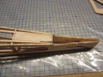
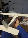
Willy Nillies Eaglet 250 Build

Turbojoe

Elite member
Those wheel pants are going to look amazing! Just for looks alone they'll be worth the minimal weight gain. Looking to see more on your mounting method too.

The windshield hatch is super easy. Just glue the windshield and cowl top together. Add a tongue and magnet or latch and you're done. I did the same thing on my Telemaster 40.

Joe
 

speedbirdted

Legendary member
Sexy wheel pants! I need to see the other side and how you mount them to the wire. Didn't you get an electric motor firewall with air holes in it?

View attachment 160554

Turbojoe and I both made top hatches for our Eaglets.

Jon
I did get an electric motor firewall. However the mounting holes for the motor don't line up with my motor and I think drilling more holes that close to other holes would compromise its strength, so i used the one with no holes in it and will go drill all of them later. I am going to mount the wheel pants with small neodymium magnets or in the event that i don't foresee them moving for any reason they will just get epoxied on.

Those wheel pants are going to look amazing! Just for looks alone they'll be worth the minimal weight gain. Looking to see more on your mounting method too.

The windshield hatch is super easy. Just glue the windshield and cowl top together. Add a tongue and magnet or latch and you're done. I did the same thing on my Telemaster 40.

Joe
They weigh something like 2ish grams each lol. I'm pretty sure adding the float mounts was more weight.
 

Willy Nillies

Elite member
Great work there SpeedBirdTed!

What motor are you using? If there is another common motor mount spacing that we aren't aware of, we'd like to know so we can figure something out to include in the kits.

Sincerely,
Doug and Becky
WillyNillies.com
 

Turbojoe

Elite member
I did get an electric motor firewall. However the mounting holes for the motor don't line up with my motor and I think drilling more holes that close to other holes would compromise its strength, so i used the one with no holes in it and will go drill all of them later. I am going to mount the wheel pants with small neodymium magnets or in the event that i don't foresee them moving for any reason they will just get epoxied on.


They weigh something like 2ish grams each lol. I'm pretty sure adding the float mounts was more weight.

Because they're forward of the CG it may actually help you with balance. Some of us end up tail heavy even with trike gear. They look so good they'll be worth any extra work required.

Joe
 

speedbirdted

Legendary member
Great work there SpeedBirdTed!

What motor are you using? If there is another common motor mount spacing that we aren't aware of, we'd like to know so we can figure something out to include in the kits.

Sincerely,
Doug and Becky
WillyNillies.com
P_20200307_224711.jpg


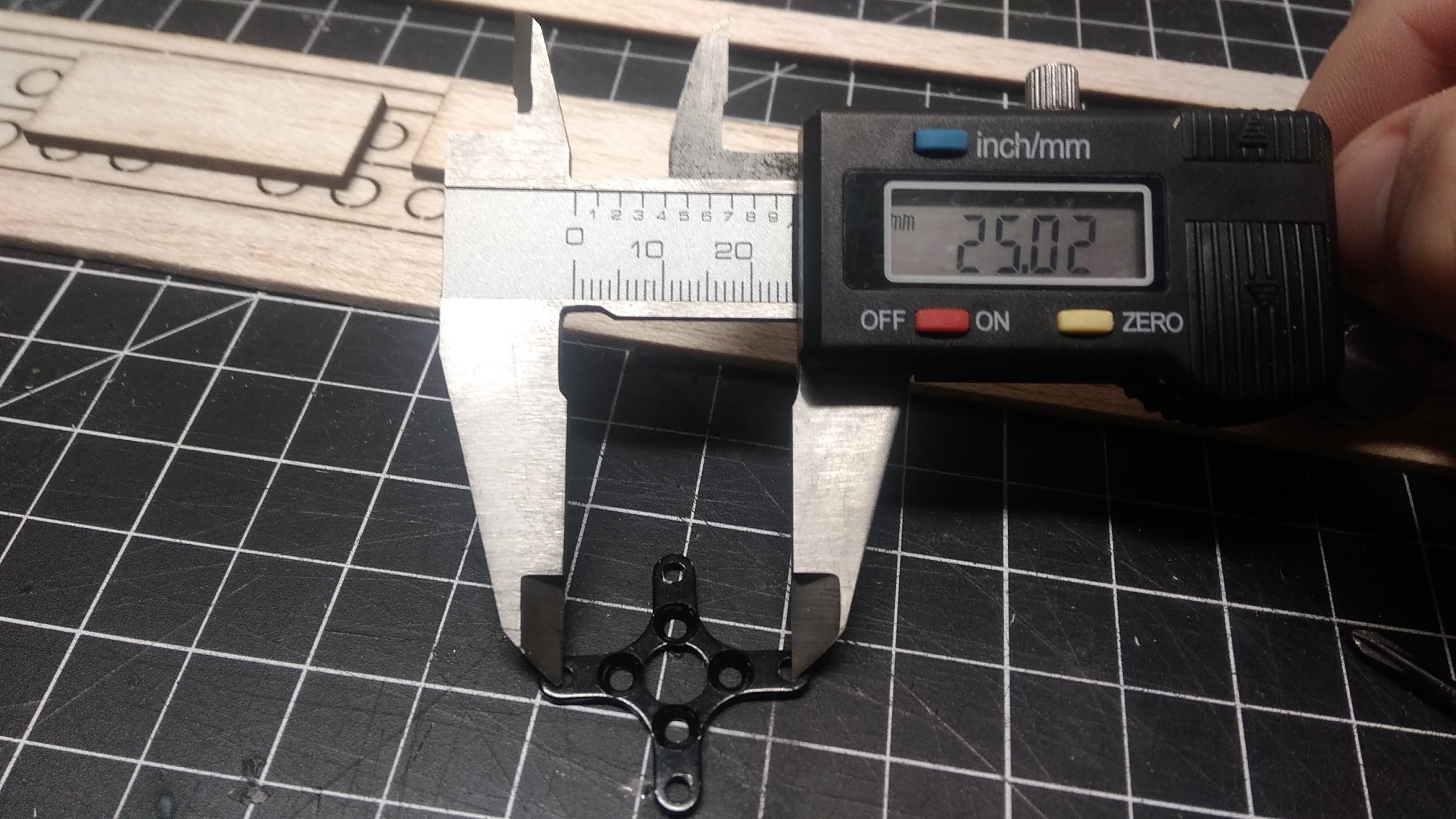
I'm not entirely sure how common this motor mount size is so I don't know how practical it would be to supply a third firewall option with this hole spacing. I have quite a lot of motors and so far the only size ones I have that have this mount are 1510.

Another question - is there not a brace included in the kit that runs between wing halves, other than the ones at the leading and trailing edges? That seems like it would make the wings awfully weak. I might rig up something custom out of 1/16 ply, which shouldn't be too hard given I'm using the 0° dihedral pieces.
 

TooJung2Die

Master member
Another question - is there not a brace included in the kit that runs between wing halves, other than the ones at the leading and trailing edges? That seems like it would make the wings awfully weak.
It's not an issue on an airplane this small and light. On a larger heavier airplane, yes, you'll want a stronger dihedral brace. I have the Skylark 250 coming and I don't intend to use the included shear webs this time. It's overkill. I built electric RC conversions of rubber powered airplanes with longer wingspans and much lighter wing construction than the Eaglet. Similar weight and no wing flex issues.
 

Willy Nillies

Elite member
View attachment 160666

I'm not entirely sure how common this motor mount size is so I don't know how practical it would be to supply a third firewall option with this hole spacing. I have quite a lot of motors and so far the only size ones I have that have this mount are 1510.

Another question - is there not a brace included in the kit that runs between wing halves, other than the ones at the leading and trailing edges? That seems like it would make the wings awfully weak. I might rig up something custom out of 1/16 ply, which shouldn't be too hard given I'm using the 0° dihedral pieces.

Hi There,

The motor mount we supplied in the kit won't bolt up to your motor?

The wing as designed is much stronger than you think. Adding an extra dihedral brace will be simply adding weight.

Sincerely,
Doug and Becky
WillyNillies.com
 

Willy Nillies

Elite member
Unfortunately, no. The holes in the mount line up, but the screws that mount the motor to the mount are not long enough.

Wow! They must have supplied some very very short screws with your motor! :unsure: Are your motor screws 2mm or 3mm diameter? The 1306/1806 use 2mm diameter socket head x 3mm long screws and work very well in our plastic motor mounts.

Sincerely,
Doug and Becky
WillyNillies.com
 

speedbirdted

Legendary member
Wow! They must have supplied some very very short screws with your motor! :unsure: Are your motor screws 2mm or 3mm diameter? The 1306/1806 use 2mm diameter socket head x 3mm long screws and work very well in our plastic motor mounts.

Sincerely,
Doug and Becky
WillyNillies.com
Diameter is 2mm. They are very short indeed - however the mount you supplied looks like it has recessions for the screw heads to go down into... which would let me use it if the screw heads weren't too wide, which prevents the very short screws from actually going into the motor like they should. I could drill it out but that would risk breaking it. I'd rather keep it around so when I have a motor I can actually use it with it's there :p
 

speedbirdted

Legendary member
Wing is coming along nicely. Just the remaining bits of sheeting and shear webbing to do. I built the option for zero dihedral. I think I'll also add the angled wingtips like some people here have done (if my LHS sells tri strips big enough - their balsa selection is usually pretty worthless) After some quick measurements I determined with the flap servo in the middle of the wing it wouldn't clear the elevator and rudder servos so I had to move it to the side. I'm not going to be using servo cable extensions for the outer wing servos, instead I'm going to cut the cables and solder on longer ones. I like doing this because it both saves servo extensions and cuts down on the number of failure points.

In case you hadn't already figured it out, the ailerons will be split at the 5th rib (the one the servo is mounted in)

P_20200309_014206.jpg


And a family photo, because why not? This plane is adorable.

P_20200309_020408.jpg
 

speedbirdted

Legendary member
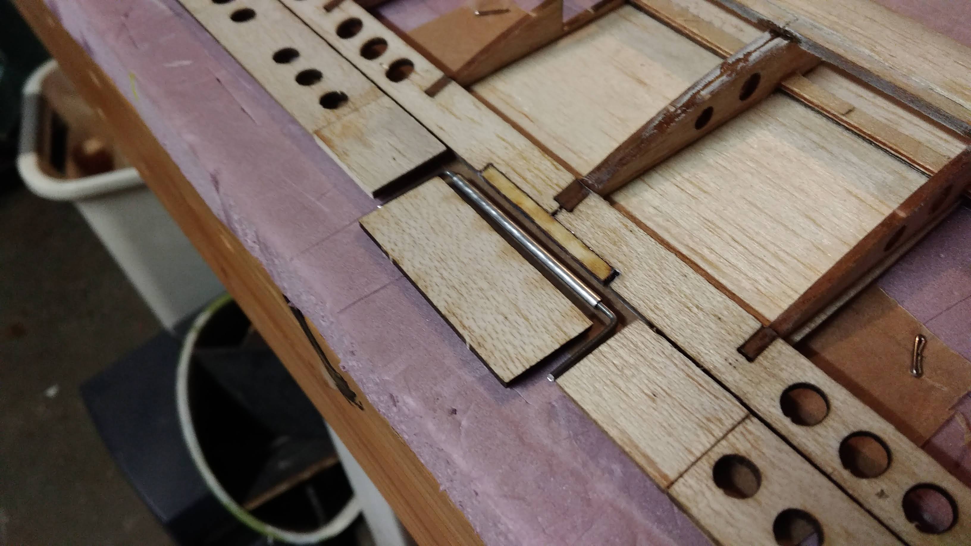
A lousy update, but I've figured out the flap system (mostly.) I decided to cut one of the weird spacer thingies and glue the halves to the inner flap edges - the flaps will be a little more effective if the amount of room the air has to escape between the fuselage and the flap is smaller. Plus, the gap looks kind of weird.

I found some 3/32 aluminum tubing that fits over the supplied landing gear wire perfectly and also is narrow enough to fit flushly against the wing trailing edge. Though I think I'm still going to run a piece of 1/32 sheeting on both sides of the joint just to hide the tube better and maybe add some stiffness. Installation is going to be a bit tricky - my technique to get absolute 100% coverage on both the wing and control surface and still get the hinges glued properly is always to cover the stuff and then cut the slots for hinges and glue them afterwards... however due to the way the flaps get installed here I might have to cover the little bit of the wing that is inaccessible when the control surface is installed, epoxy the flaps to the wire and cover them, then hinge everything and get the tube epoxied in, and then finish the covering job...

P_20200312_004150.jpg
 

Turbojoe

Elite member
Looking good so far. If I may make a suggestion add another layer of strength to the trailing center section. I don't remember why I didn't convert the Eaglet to bolt on wing as I did on the Supper Sport and the Jr. Skylark but I still added a layer of 1/64" ply top and bottom in that area. That small amount weighs virtually nothing and adds tons of strength. The only picture I took of it was from the Skylark build though.

Joe

IMG_0028.JPG
 

speedbirdted

Legendary member
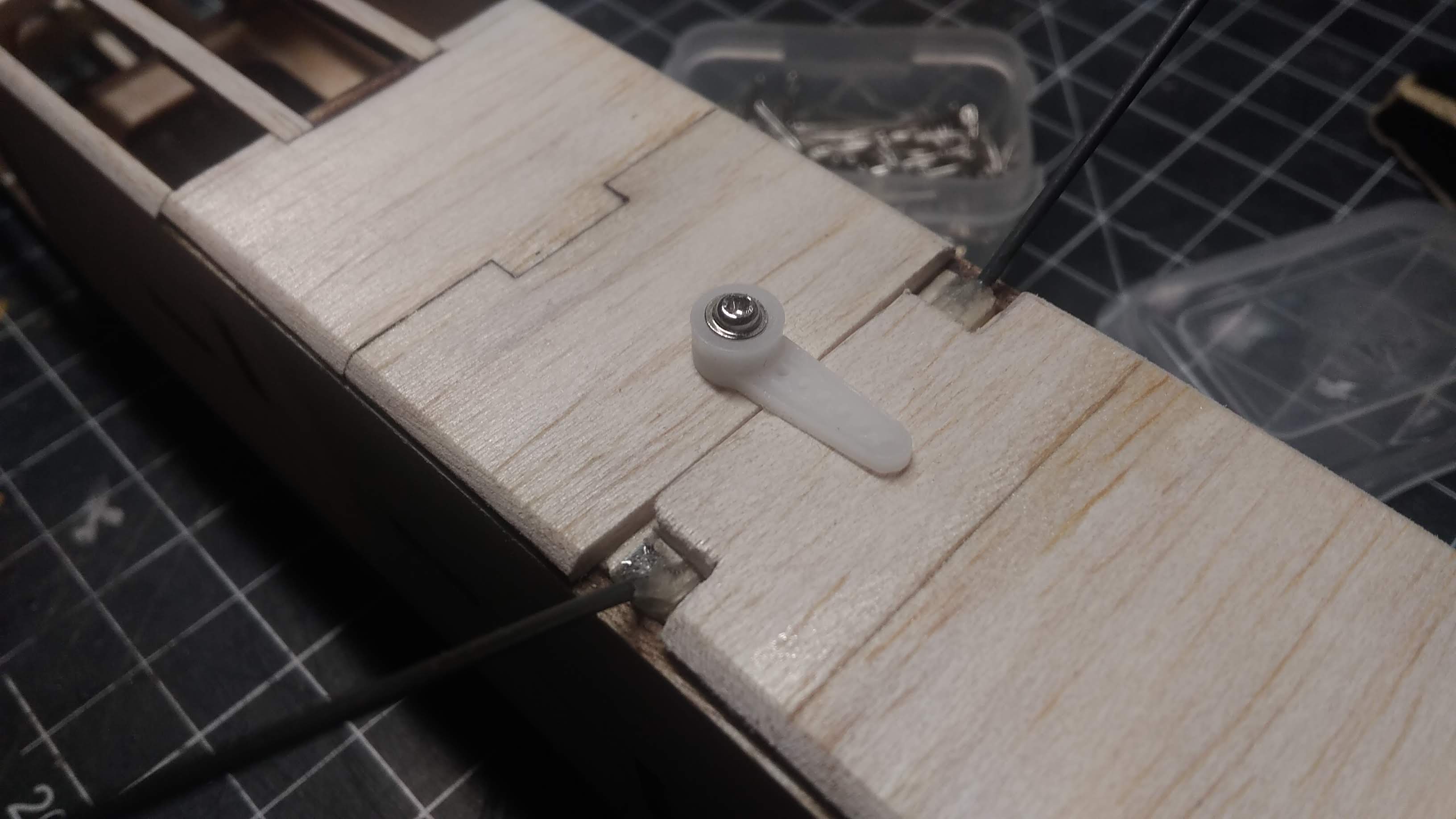
I got a lot done today but didn't take a lot of pictures. Usually it's the other way around :ROFLMAO: Built the top hatch with neodymium magnets and finished off the bottom. I shouldn't have glued the screw in before I put the covering down - but whatever, it's not a huge deal. Servo horns are incredibly useful, even when off of servos!

P_20200313_020602.jpg


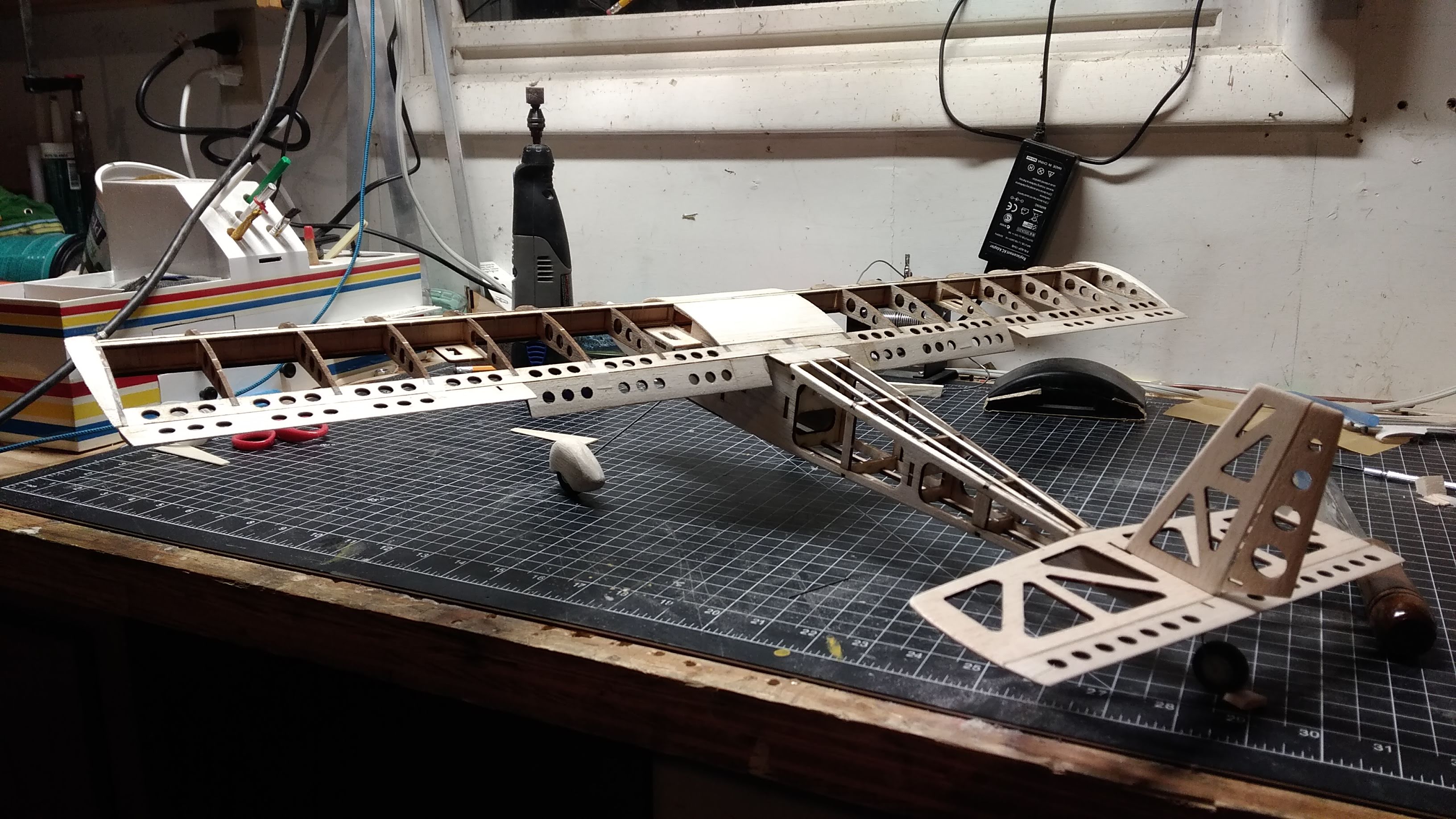
Many of you probably also want to see some naked airplane action. Fear not...

P_20200313_025733.jpg


Very little is permanently attached here. The whole tail will wait until it's fully covered before it goes on - it helps massively with ease of covering, and most ARFs go together something like that so it must not pose many other problems.

Another question - how are people routing the rudder pushrod? I want to just put a Z-bend in it and route it in between the two outer top stringers, but I was also thinking since I moved the vertical stab and rudder back maybe I could get away with running a tube through the horizontal stabilizer to house the pushrod. That would be more weight....
 

speedbirdted

Legendary member
Your idea of putting the rod through a tube and coming out of the horizontal stab would be cleaner looking. I prefer push rods through tubing.

My other worry with that idea is it would add a significant bend that the pushrod would have to go around which would load the servo up more. If anything is certain about these tiny servos, they are fragile, and I don't want to place any more strain on it than I have to.
 

Turbojoe

Elite member
I did pretty much the same as Jon but both pushrods exit on the same side. Dictated by the use of the steerable nose wheel. I just used the Dubro micro pushrods and guide tubes. If you keep the angle shallow it shouldn't be a problem coming through the H-stab. You're right about the servos. They strip easily. I killed on on the bench! I now just use it for setup only.

Joe

IMG_0005.JPG IMG_0011.JPG
 

speedbirdted

Legendary member
I'm also using the Dubro pushrods but I only used the guides for the little bit where it runs through the fuselage formers to cut down on tail weight and protect the wood. I like both of those methods, but I'm a bit skeptical of the first one because me moving the rudder back might cause the pushrod to be able to flex between the Z-bend and rudder and lose some rudder authority. Oh well, I have plenty of wire available, so I might as well explore both options.
 

Turbojoe

Elite member
With the relatively tiny .032 wire I would have used the full length of the pushrod tubes to negate any possible flex between bulkheads but that's just me overdoing things. Hey, let's face it, at the speed this bird will fly there just isn't a lot of aero force on the rudder so just about any linkage you decide upon will likely work fine.

Joe
 
I got a lot done today but didn't take a lot of pictures. Usually it's the other way around :ROFLMAO: Built the top hatch with neodymium magnets and finished off the bottom. I shouldn't have glued the screw in before I put the covering down - but whatever, it's not a huge deal. Servo horns are incredibly useful, even when off of servos!

View attachment 161231

Many of you probably also want to see some naked airplane action. Fear not...

View attachment 161232

Very little is permanently attached here. The whole tail will wait until it's fully covered before it goes on - it helps massively with ease of covering, and most ARFs go together something like that so it must not pose many other problems.

Another question - how are people routing the rudder pushrod? I want to just put a Z-bend in it and route it in between the two outer top stringers, but I was also thinking since I moved the vertical stab and rudder back maybe I could get away with running a tube through the horizontal stabilizer to house the pushrod. That would be more weight....
Like everyone else, I ran a tube guide from the former to the top of the tail. Sanding the tube flush allows for a small exit hole.

I like the idea of adding the zbend, I'll have to see when I attach the control surfaces. I'm almost finished with painting them, then the trim, windows, clear coat, and then attach the control surfaces using fishing line and CA glue.
 

Attachments

  • 20200126_123634.jpg
    20200126_123634.jpg
    1.2 MB · Views: 0
  • 20200302_171831.jpg
    20200302_171831.jpg
    1.3 MB · Views: 0