***I was sent the mechanical parts at no cost to help beta test this kit.

So a few months back Martin, a fellow Hobbyist local to the Bay Area, asked if i would be interested in helping him beta test a hot wire cnc kit he was developing. Now i have had an interest in hot-wire cutting foam for probably 7 years, ever since i first watched some of Andrew Newton's videos on YouTube. I have built my own hot wire cutter out of MDF and drawer slides and even before that i was manually cutting wings using fishing wire and aluminum flashing templates. So I was very excited to try out a manufactured kit. A few weeks later i received the v1 kit from him and the electronics i needed from amazon.


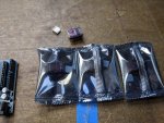


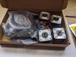
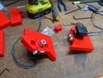
The rails are extruded aluminium and the connecting pieces are 3d printed parts with metric hardware. The controller is Arduino based with a cnc shield and the motors are Nema17's. Although i find i am not using them daily, the kit does come with 4 limit switches. I will explain why i dont use them often later.
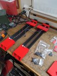
Now, as i stated i have built a 4 axis kit from scratch using mdf and drawer slides, so this isnt my first time and i do know how everything "should" function. I have also built a 3d printer from a kit. But having said that, the build was very, very, very simple in comparison. As i said back to martin, i think if i had to build this again i could do it in under an hour. Now this is building the 2 complete towers. It took longer than that to get it up in working, probably 3 or 4 evenings. The longest part, and he is looking into how to remove this step, was extending all the stepper motor wires as the length cannot make the 40" of travel. So lots of soldering extensions onto the cables. And than depending on how much time you take, getting the 40x40 piece of mdf square with the two towers can take some time. Martin has a very convenient drill template to assist with placing the holes.
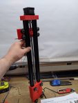

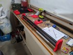


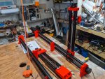


The cnc shield i have can take 12-35v. I had an adjustable power supply on hand and made a little project box out of some scrap #wewd. This brings up a very nice feature of the table. You have a good 4.5 inches of space under the mdf to hide all the messy bits. Also, as i have a problem with leaving things on, i added a voltmeter to not only display the voltage going to the arduino but it also acts as an "on" light for me. Although in hindsight you can hear the nema motors when they are on, but it looks cool.

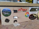

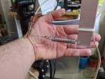
A cutting bow does not come with the setup, but this is a very easy thing to make. I grabbed some angled aluminium from Ace hardware ($16) and some rivets and made the one seen above. For cutting wire i had some Rene 41 27g wire on hand. I used a very strong spring from the hardware store and some zip ties to break the electrical connection to the aluminium on one end (fyi this was NOT what i did at first lol. Yes springs can glow red). To power the hotwire itself i have a $60 adjustable power supply from banggood. The bow just rests on the arms of the towers with guides that keep the pivot points from moving. I measured the table to see what the length would be if the towers were at extreme angles, basically a 45 degree angle. That way one tower can be all the way forward and other tower all the way on the opposite side and the bow will reach. This is how you can get away with little nema17's, all the tension is in the bow, not between the towers.


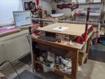
Here are some later pictures of the table as i am using it today. I added some measuring tape stickers to help with foam alignment, put my pc in a better location and pimped out the table with some stickers of my favorite wing makers. I also keep a drywall square on hand as this helps with getting everything perpendicular. Its a pretty big table as you can see. The cutting dimensions are 1145mm between pivot points, 880mm of travel on X and 330 on Y. Thats a pretty big area. While the 880mm depth is set, you could make the distance between towers more or less. If your going to be doing some extreme sweep you will want the towers closer together. Although devWing software does have some tricks to assist with this. You can see some of the things i have cut at the bottom of this post.


Now the one part i was kind of dreading was the Arduino setup as I hate programming. The physical wire connections are very clear in the instructions. The one "fiddly" part was adjusting the vref setting for each board on the cnc shield. There are 4, one for each nema motor. The vref is a reference, in voltage, that you adjust to tell the boards the maximum amps your nema motors will take. It requires a small screw driver and a multi-meter. It was easy, just takes time. As far as the programming part its a simple as plugging the Arduino into your windows pc via its usb cable and selecting the appropriate Arduino and shield in the software. Thats it. Done. I immediately had control of the motors. Its that easy.
As i mentioned the kit comes with 4 limit switches. Myself, personally, I like my "home" position to be the upper corner of the mdf table. This makes it very easy to center up foam. I just reference that corner. So i manually adjusted all 4 towers, in the CAM software, to line up at that position and just barely above the mdf. And i set that as my "home" in software. That sets all towers to Zero at that point. Every time i am done with a cut, i tell the towers to "go to origin" and they go back to that exact same point, and i turn off the Arduino. So next time i turn the system on, its already at zero and i can just start again. So, in my case, i dont actually use the limit switches daily. In my CAM software i have also set some "soft limits". I measured out how much travel i had, minus about 5mm just to be careful, and entered those. That way the CAM software will automatically stop travel even if the gcode says to keep going. And at the near side, if for some reason i forgot to return to home and the starting point got offset, it will still hit those physical limit switches and automatically stop.
The next thing you should do, no matter which software you are using, is to do a "drag" test. I dont know what this is called thats just what i call it. Basically you are going setup a piece of foam at a "usual" length. You are doing a test cut on a average width of foam. The point is to find the best cutting temp for that foam. Each type of foam is going to require a different temperature setting. White rigid foam has a lower melting point than dense pink or blue or even EPP.
So setup a block on the table. Setup the wire so that it is about 5 mm below the top of the foam sheet. Start moving the towers forward at the same speed you will be cutting at. Basically we are slicing a 5mm sheet off the top. Now adjust your volts and amps. If the foam starts "dragging", moving, turn the power up until it doesnt move at all. If your foam isnt moving, keep turning the power down until it does. The goal is to find that sweet spot where the wire is not even touching the foam, but the radiant heat is melting the foam before the wire gets to it. You want this "kerf" to be as small as you can. I keep a little notepad with the volts/amps i use for various projects. This will be something you will play with forever. Finding the right setting for each project.
For reference, the speed i am cutting at is 2mm/sec
Lets talk about software. I am going to do some more in depth and specific posts about the software, but i will briefly mention what i am using here.
Being that this is Arduino and CNC shield based you could very well get by with any number of free to use software such as Fusion360. But i have been "getting by" with free software for the past 2 years and i was ready to move on to some purchased, but specifically made software. In this case devCad's software packages. For the CAM, the software that you load cutting files into and directly control the arduino, i went with devCNC. It is specifically made for this application. For the design side i initially purchased devWing Foam 2 and than also picked up devFoam LE. Both of these are made to export cutting files not only specifically for devCNC but for any CAM like linuxcnc or the more widely used mach3.
devWing is software specifically made for designing wings that will be cut out of foam. Its amazing. Has way more options than i need but also lets you skip those sections easily. I spend more time drawing out a plan on paper or inkscape than i do in this software. Like 5 minutes to design a wing and get a cutting file out.

defFoam is for cutting 2d objects out. Letters, numbers, anything you can design, like for instance a fuselage profile or wingtip. I design a shape in inscape, export as dxf, import into devfoam and tell it one of its dimensions are. Really quick.

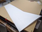
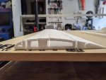
Since i got it together and working i have basically been doing nothing else with my hobby time but designing and cutting things on this. Here are some of the things i have done so far:






Heres Martin flying a wing he cut on the cnc:
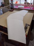
Heres a fpv wing im working on that i cut a few days ago:

Im sure im forgetting stuff, ill update this as i can and as questions come in. Im also going to start doing a bunch of "all the way thru" videos where in real time i make a cutting file and take it to the cnc. It takes longer to cut the foam out than to design it. As i said at the beginning, i was sent these parts at no cost but I would say i am more biased towards this because i really love cutting wings out of foam lol. But having said that i cannot say enough about this current setup of the windyhillhobby cnc and the devcad software. It just works. Heres an exact copy of what i told him a few days ago: " I'm having a total blast using this machine It in combination with the new software is like all of the roadblocks to like creatively getting my thing into the real world are just gone and I just think of something put it in the program and it just like comes out it's awesome".
Thats really how it is. I have an idea in my head, i document it in inkscape using real world numbers, spend about 5-10 minutes in devCad software, than walk out to my shop, load the file, cut the foam to shape and hit "start". And bam the wing appears.
Go check out https://windyhillhobbies.com/
https://www.instagram.com/windyhillhobbies/

So a few months back Martin, a fellow Hobbyist local to the Bay Area, asked if i would be interested in helping him beta test a hot wire cnc kit he was developing. Now i have had an interest in hot-wire cutting foam for probably 7 years, ever since i first watched some of Andrew Newton's videos on YouTube. I have built my own hot wire cutter out of MDF and drawer slides and even before that i was manually cutting wings using fishing wire and aluminum flashing templates. So I was very excited to try out a manufactured kit. A few weeks later i received the v1 kit from him and the electronics i needed from amazon.


The rails are extruded aluminium and the connecting pieces are 3d printed parts with metric hardware. The controller is Arduino based with a cnc shield and the motors are Nema17's. Although i find i am not using them daily, the kit does come with 4 limit switches. I will explain why i dont use them often later.
Now, as i stated i have built a 4 axis kit from scratch using mdf and drawer slides, so this isnt my first time and i do know how everything "should" function. I have also built a 3d printer from a kit. But having said that, the build was very, very, very simple in comparison. As i said back to martin, i think if i had to build this again i could do it in under an hour. Now this is building the 2 complete towers. It took longer than that to get it up in working, probably 3 or 4 evenings. The longest part, and he is looking into how to remove this step, was extending all the stepper motor wires as the length cannot make the 40" of travel. So lots of soldering extensions onto the cables. And than depending on how much time you take, getting the 40x40 piece of mdf square with the two towers can take some time. Martin has a very convenient drill template to assist with placing the holes.


The cnc shield i have can take 12-35v. I had an adjustable power supply on hand and made a little project box out of some scrap #wewd. This brings up a very nice feature of the table. You have a good 4.5 inches of space under the mdf to hide all the messy bits. Also, as i have a problem with leaving things on, i added a voltmeter to not only display the voltage going to the arduino but it also acts as an "on" light for me. Although in hindsight you can hear the nema motors when they are on, but it looks cool.


A cutting bow does not come with the setup, but this is a very easy thing to make. I grabbed some angled aluminium from Ace hardware ($16) and some rivets and made the one seen above. For cutting wire i had some Rene 41 27g wire on hand. I used a very strong spring from the hardware store and some zip ties to break the electrical connection to the aluminium on one end (fyi this was NOT what i did at first lol. Yes springs can glow red). To power the hotwire itself i have a $60 adjustable power supply from banggood. The bow just rests on the arms of the towers with guides that keep the pivot points from moving. I measured the table to see what the length would be if the towers were at extreme angles, basically a 45 degree angle. That way one tower can be all the way forward and other tower all the way on the opposite side and the bow will reach. This is how you can get away with little nema17's, all the tension is in the bow, not between the towers.


Here are some later pictures of the table as i am using it today. I added some measuring tape stickers to help with foam alignment, put my pc in a better location and pimped out the table with some stickers of my favorite wing makers. I also keep a drywall square on hand as this helps with getting everything perpendicular. Its a pretty big table as you can see. The cutting dimensions are 1145mm between pivot points, 880mm of travel on X and 330 on Y. Thats a pretty big area. While the 880mm depth is set, you could make the distance between towers more or less. If your going to be doing some extreme sweep you will want the towers closer together. Although devWing software does have some tricks to assist with this. You can see some of the things i have cut at the bottom of this post.


Now the one part i was kind of dreading was the Arduino setup as I hate programming. The physical wire connections are very clear in the instructions. The one "fiddly" part was adjusting the vref setting for each board on the cnc shield. There are 4, one for each nema motor. The vref is a reference, in voltage, that you adjust to tell the boards the maximum amps your nema motors will take. It requires a small screw driver and a multi-meter. It was easy, just takes time. As far as the programming part its a simple as plugging the Arduino into your windows pc via its usb cable and selecting the appropriate Arduino and shield in the software. Thats it. Done. I immediately had control of the motors. Its that easy.
As i mentioned the kit comes with 4 limit switches. Myself, personally, I like my "home" position to be the upper corner of the mdf table. This makes it very easy to center up foam. I just reference that corner. So i manually adjusted all 4 towers, in the CAM software, to line up at that position and just barely above the mdf. And i set that as my "home" in software. That sets all towers to Zero at that point. Every time i am done with a cut, i tell the towers to "go to origin" and they go back to that exact same point, and i turn off the Arduino. So next time i turn the system on, its already at zero and i can just start again. So, in my case, i dont actually use the limit switches daily. In my CAM software i have also set some "soft limits". I measured out how much travel i had, minus about 5mm just to be careful, and entered those. That way the CAM software will automatically stop travel even if the gcode says to keep going. And at the near side, if for some reason i forgot to return to home and the starting point got offset, it will still hit those physical limit switches and automatically stop.
The next thing you should do, no matter which software you are using, is to do a "drag" test. I dont know what this is called thats just what i call it. Basically you are going setup a piece of foam at a "usual" length. You are doing a test cut on a average width of foam. The point is to find the best cutting temp for that foam. Each type of foam is going to require a different temperature setting. White rigid foam has a lower melting point than dense pink or blue or even EPP.
So setup a block on the table. Setup the wire so that it is about 5 mm below the top of the foam sheet. Start moving the towers forward at the same speed you will be cutting at. Basically we are slicing a 5mm sheet off the top. Now adjust your volts and amps. If the foam starts "dragging", moving, turn the power up until it doesnt move at all. If your foam isnt moving, keep turning the power down until it does. The goal is to find that sweet spot where the wire is not even touching the foam, but the radiant heat is melting the foam before the wire gets to it. You want this "kerf" to be as small as you can. I keep a little notepad with the volts/amps i use for various projects. This will be something you will play with forever. Finding the right setting for each project.
For reference, the speed i am cutting at is 2mm/sec
Lets talk about software. I am going to do some more in depth and specific posts about the software, but i will briefly mention what i am using here.
Being that this is Arduino and CNC shield based you could very well get by with any number of free to use software such as Fusion360. But i have been "getting by" with free software for the past 2 years and i was ready to move on to some purchased, but specifically made software. In this case devCad's software packages. For the CAM, the software that you load cutting files into and directly control the arduino, i went with devCNC. It is specifically made for this application. For the design side i initially purchased devWing Foam 2 and than also picked up devFoam LE. Both of these are made to export cutting files not only specifically for devCNC but for any CAM like linuxcnc or the more widely used mach3.
devWing is software specifically made for designing wings that will be cut out of foam. Its amazing. Has way more options than i need but also lets you skip those sections easily. I spend more time drawing out a plan on paper or inkscape than i do in this software. Like 5 minutes to design a wing and get a cutting file out.

defFoam is for cutting 2d objects out. Letters, numbers, anything you can design, like for instance a fuselage profile or wingtip. I design a shape in inscape, export as dxf, import into devfoam and tell it one of its dimensions are. Really quick.

Since i got it together and working i have basically been doing nothing else with my hobby time but designing and cutting things on this. Here are some of the things i have done so far:


Heres Martin flying a wing he cut on the cnc:
Heres a fpv wing im working on that i cut a few days ago:

Im sure im forgetting stuff, ill update this as i can and as questions come in. Im also going to start doing a bunch of "all the way thru" videos where in real time i make a cutting file and take it to the cnc. It takes longer to cut the foam out than to design it. As i said at the beginning, i was sent these parts at no cost but I would say i am more biased towards this because i really love cutting wings out of foam lol. But having said that i cannot say enough about this current setup of the windyhillhobby cnc and the devcad software. It just works. Heres an exact copy of what i told him a few days ago: " I'm having a total blast using this machine It in combination with the new software is like all of the roadblocks to like creatively getting my thing into the real world are just gone and I just think of something put it in the program and it just like comes out it's awesome".
Thats really how it is. I have an idea in my head, i document it in inkscape using real world numbers, spend about 5-10 minutes in devCad software, than walk out to my shop, load the file, cut the foam to shape and hit "start". And bam the wing appears.
Go check out https://windyhillhobbies.com/
https://www.instagram.com/windyhillhobbies/
Last edited:


