Looking around I found this from a
Scale Modeling site;
I copied this from
here I think. Don't know the original poster, but credits to him.
If you have ever had a hankering to build a biplane, but have been put off by the rigging, or any of the other issues that are unique to them, then hopefully this little blurb will make things a little clearer and easier to understand. While I claim to be no expert, I have done enough of it to be comfortable enough to share my techniques and trials and tribulations learned over the years. If you have any input I would be glad to hear from you, just drop me an email at
mr1057@frontiernet.net and let me know your ideas, or questions.
Background.
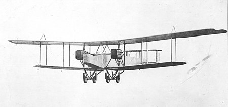
Most biplane wings are divided up into bays or cells. Visualize a box in between the top and bottom wing, with the wing struts comprising the corners of the box. Within the box is your bay, or cell. So when its said the wing is a 4 bay or 4 cell wing, it means there are two cells on the left, two cells or bays on the right, with the fuselage center being the divider. Most biplanes are rigged the same way; X bracing fore and aft between the struts, and landing and flying wires in an X pattern between each bay running span wise. Some aircraft used doubled flying and landing wires, so check your references. A flying wire extends from the inside of the bottom wing to the outside of the top wing. Conversely, Landing Wires run from the inside of the top wing, down to the outside of the bottom wing. They are named for the loads they take. Landing wires absorb load from a negative G direction, Flying Wires absorb loads from a positive G direction.
Rigging.
There are several different techniques that can be used. We will cover the two I most commonly use, elastic thread and nylon monofilament. I gave up on stretched sprue a long time ago for various reasons. I could never pull a strand that was consistent in thickness from one strand to another, and it lends very little strength to the model. Plus I am hamfisted enough to usually break one or two strands during the rigging process. We will also cover the tools of the trade that make it easier to rig a model.
Elastic Thread. Sold under the trade name Lycra, this is a small diameter multi filament thread, which will stretch to 50% of its relaxed state. I use it for any rigging that does not contribute to any structural stability, i.e. control runs, internal wire bracing, antennae wires, etc. If the model you have built is strong structurally and does not need further strengthening from the rigging, it can also be used for bracing, flying and landing wires. As it implies, it contributes nothing to airframe stiffness, it is strictly for appearance. It is very easy to work with, and requires a minimum of practice to get it down. The steps in rigging with Lycra will be covered in depth.
Monofilament This is, as the name implies, a single strand nylon line, most generally used for fishing, or for heavy duty sewing needs. It usually comes in clear, but I have seen smoke colored line. It comes in a variety of thicknesses, and from several different sources. I use Aeroclub Mail Order from the UK for my elastic and monofilament needs. The price is cheap, and you have your order usually in about 5 days. Do a search for Rigging and you will find it in their online catalogue. The advantage of nylon is that it is very strong and contributes to the strength of the model. If you have a very petite airframe and need the additional bracing, monofilament is the way to go. The drawback is it has to be drawn tight when installing, as it does not heat shrink like stretched sprue does. We will cover the method to do so later on.
Tools / Materials required:
- Small scissors.
- Small tweezers, preferably cross action, at least 2 pair.
- Ruler (6 scale is usually sufficient)
- Pin vise with straight pin and a #75 drill bit (or close to it)
- Black Permanent Marker or Paint Stick (or your choice of color you want the wires)
- Masking Tape
- CA Adhesive (thick gap filling variety, not Gel)
- CA Accelerator
- Accelerator applicator. ( I use a piece of music wire)
Preparation
One of the most critical steps in a successful rigging job is preparation. Misaligned rigging can really detract from a model, so the extra care spent in layout pays huge dividends. The best time to layout rigging holes is BEFORE the model is assembled and painted. This way you can use a pencil to layout alignment lines, and then rub them off after. Lets begin with the wings.
It is assumed that you have your strut locations known at this point if its a kit, or you already have them laid out if a scratchbuilt wing. Check your plans and references before drilling any holes to determine the number of Flying/Landing wires you need to drill. Once this is determined, its time to layout your rigging holes and drill them. I generally space my landing/flying wires out from the strut hole about 1mm, but this is subject to accuracy. If you are not working from 3-views, then eyeballing it from a good clear photo should give you an idea how far away to make them. Begin by drawing a pencil line from tip to root, using the strut holes as a guide. Do this for front and rear struts if equipped. V strut wings may only require one line. Now using a small square, square off these lines and draw lines between the strut holes for your inter strut bracing. On both sides of this line, draw a parallel line the determined distance from your strut hole, for the flying and landing wires. Remember, on the outermost struts, there may not be flying wires, and rarely any landing wires, (check your references again) so odds are good you wont need holes on the outside of those strut holes. Where these pencil lines intersect is where you will make the holes.
Drilling holes.
Depending on what technique you are using determines how deep you drill the holes. If you are using Lycra Thread, then you only need to drill to a depth of 1 mm or so. If you are using monofilament, then you will drill completely through the wing so that the hole goes all the way through on the bottom wing. On the underside of the top wing, drill ½ the thickness of the wing. We will cover why later.
Using the pinvise with a sharp straight pin chucked in place, center punch all the intersecting pencil lines to prevent the drill bit from walking when you drill. The method you use to drill is entirely up to you, but I have found a Dremel set to low speed makes short order of the holes, but a steady hand and a pinvise with a #75 or so drill bit works just as well, it just takes longer. Once all your holes are drilled, relax and have a beer or drink of your choice; you have earned it. The same methods work for fuselage rigging and tail plane rigging. Just remember the mantra, measure twice, mark once, drill once. Always double check your dimensions and never assume you have it right… always double check.
Running the lines.
Okay. Your jewel is assembled, all your rigging holes are drilled, and you are about to cut your first line. Stop. Look it over and determine an order of rigging. Generally speaking, working from the inside out makes the most sense, trying to run lines in between existing lines can be enough to make your little jewel become airborne into the nearest wall at a fatal velocity.
Now we can cut lines and begin gluing them in place. If you are using mono, length is not a concern. The rule of thumb I use is to cut your line about 2 inches longer than what you need. This will allow for your tweezers to act as a weight to keep your line taught as you glue it in place. More on this later.
For Elastic, use a ruler to measure the distance your line needs to be. It does not have to be accurate; remember this stuff stretches. Unroll a couple of feet off the spool, and using the permanent marker, draw it along the line several times to color it. Let it dry for a few minutes, then lay the line on your ruler at the determined length and cut it off. Make as many as you need, as you will find most of them will be roughly the same length.
Now the fun begins. Remove the drill bit from your pinvise and install a common straight pin. This will be your CA applicator to get the glue into the hole. Put two strips of masking tape down on an area of your workbench that is out of the way, but easy to reach. You dont want to rest your elbow in it and become one with your bench. Put a drop of CA on the tape, and stick your pin into it, so that a tiny drop forms on the point. Touch the tip of the pin onto the side of the hole and let capillary action pull the CA into the hole. A little practice on some scrap holes may be in order until you get the feel for it. You dont want the CA to be above the surface of the wing, just enough to fill the hole. After 3 or 4 holes are filled, you may find it necessary to remove any excess CA buildup on the tip of the pin. For the first end, no accelerator is needed, just poke the line into the hole and let it cure. Repeat this to as many lines as you feel comfortable with.
(Hint: Install all the landing/flying wires and X bracing into the underside of the top wing before you install it onto the model. It is much easier than trying to install them later when it is assembled.)
Once these have cured, you can begin gluing them into the bottom holes. To accomplish this, I generally check the length by stretching the line to the hole and seeing how taught the line is. If it is loose, I cut just enough so that the end of the line is about 1/8th of an inch or so away from the hole in a relaxed state, then I can stretch it to the hole and it will be nice and taught. Now using your pinvise CA applicator, put a drop of CA into the receiving hole, and add a tiny dab of accelerator to the end of your line. It may curl a bit, but it does not hurt the line any. Now, quickly, use your tweezers and stretch the line to the hole and poke it in. The accelerator will instantly cure the CA and you have one nicely installed rigging line. Repeat this procedure for as many lines as you have. Begin with the X bracing between the struts, then work your way from the center of the model outboard, stretching and gluing as you go. Once you get the knack of this, you will be amazed at how quickly you can rig a model.
For Monofilament the techniques are the same for the first end, just put a drop of CA into your anchor hole, poke it in and let it cure. The difference now will be the other end and how it is secured. Back in your preparation, you drilled the holes in the lower wing all the way through. Take the other end of your line and stuff it in the hole so that the end pokes through and out the bottom. Now using a pair of cross action tweezers, grasp the end and pull the line through the hole, and let the weight of the tweezers keep the line taught. Now using your CA applicator, add a drop of CA to the top of the hole to seize the line in place. When you get all your lines run, flip the model over upside down. There are two methods of seizing the line off, use whichever one you find easier. You can either use a sharp #11 blade and cut the excess off and add CA to the hole, or you can trim the line off, leaving about 1 or 2 mm extra, fold the line over on itself and poke it back into the hole before applying CA. The advantage of this is, the hook that is formed will become embedded in the CA in the hole and will be a very strong anchor. After all your lines are done, use a drop of CA to fill the hole off, and after it cures, a tiny brush with the same color paint the bottom has, or spray the color onto some decal film and punch out tiny circles to cover the holes, will make them invisible after flat coating.
Hopefully this will give you some idea of how easy rigging really is. I find it one of the more satisfying parts of a biplane build, as the rigging is what gives them that look and a lot of character. . I hope that as you practice the techniques here more, you will become more confident in your rigging abilities and you will find its not the endless dark tunnel that people perceive it as. As always, start with something simple with minimal rigging before you get carried away. A Fokker D-VII or a Nieuport is a good place to start, and then perhaps go to a Sopwith Camel or Albatross DV with a little more. The more you do, the more you will become comfortable.


")


