Snarls

Gravity Tester
Mentor
This is going to be a fun one. For once, I am not dealing with maximizing acrobatic performance, speed, or camera stability. No, this time it is just that: time. Flight time specifically.

My friend challenged me to a build off. Who can get the longest flight time from two 18650b batteries. Now, he did not specify what type of aircraft, configuration, and flight conditions we are limited to, but judging off the context of the conversation we had, I am assuming we are working with the well known quadcopter.

Initial Ideas:
My first instinct was to build the biggest quadcopter possible. Most of us picture a large cinematography/agricultural copter when we think long flight times, and I have always wanted an excuse to build a very large multirotor. So I started by looking at what flight times I could achieve with 18" propellers, the largest affordable ones I could find. The idea was that slow spinning props on 2s would give max flight times. This turned out to be the wrong path to go down, and here is why. Two 18650b batteries gives me either a 2s ~3400mAh battery, or a 1s ~6800mAh battery. The large AP machines with long flight times achieve this by having large rotors, but by also having very large capacity, high voltage batteries. Even with large rotors, using only two 18650b batteries won't give the longest flight times, because a typical configuration of that size is capable of carrying much more battery. So with a small battery on a large frame, the mass of the frame and components is detrimental, because a smaller quad is capable of carrying the same battery, at a more efficient percent payload. It is like flying a racing quad on a 1s 100mAh battery. It is doable, but you will benefit more from a larger, higher voltage battery.

I still would like to build a very large multirotor, but this is unfortunately not the time for that (anyone want to have a giant build off :p).

The Plan:
Thanks to a tip from my friend/competitor, I shifted my focus to something smaller, much smaller. Thanks to the wonderful multirotor calculator known as ecalc, I was able to test countless numbers of motors and propellers to achieve the best flight time.

Here is what I came up with: 1306 3100kV motors with 6x3.8 propellers on 2s. With this setup ecalc predicts a hover time of 62 minutes. A close contender was 2204 2300kV motors with 10x3.8 props on 2s, but with larger motors and props, a larger frame would be required, meaning more energy wasted on mass.

To reduce mass as much as possible, I will be using a 20x20mm flight controller and 4-in1 ESC. The receiver will be a de-cased LemonRX satellite, and I will add a mini GPS with iNav/arducopter to give me position hold. I do not want to manually fly this thing if it is flying for an hour. I could go even smaller with a 16x16mm flight stack, but I could not find anything with a barometer for use in position hold.

The frame will be as minimal as possible. Probably just a carbon rod and small supports for the motors and flight stack. The batteries will be held on by only what is necessary, and I will use something smaller than an xt30 or jst as the connector. This build will only be hovering or slowly moving, so nothing has to sustain any high acceleration.


Ecalc.jpg


Lets see what is possible :p
 

PsyBorg

Wake up! Time to fly!
Is the "quad" part set in stone or can you drop to a tri or even bit copter?

If not limited to 4 motors look into the bi copter system Litterbug is working on if the goal is just longest hover.

Also I was thinking hover is the most inefficient use of power. If you are planning Inav and gps could you set an auto path to do small ovals to unload the motors and be less resistive?
 

Snarls

Gravity Tester
Mentor
I have considered other multirotor configurations. Interestingly, ecalc suggests that anything less than a quad will have less flight time (with the same motors and props). I think the reason is that one less motor and ESC removes some weight, but there is still the weight of the FC, GPS, and batteries to be distributed across less motors. So for example my quad is projected to have a mass of 186g distributed over 4 motors (46.5g/motor). Going to tricopter (-1 motor and esc) reduces the mass to 171g over 3 motors (57 g/motor). The same trend is true for a bicopter. I also think motor efficiency has a role in this. If I go to 5 motors, I get 40.4 g/motor, but still less flight time. I believe this is because the motor/prop combo is less efficient at that loading. Of course I could try new motor/prop combinations to find ones efficient for other multirotor configurations, but I must also keep in mind the weight of servos, or extra arms and escs.

Yes, a hover may not be the most efficient. I was actually planning to place a variable speed fan next to the position held quad to find what air speed is most efficient. I think my friend intended on just hovering, but I want to see what the maximum time I can get in any condition is, whether it counts for our competition or not.
 

quorneng

Master member
I do suspect the equations used in ecalc are not going to be absolutely accurate, particularly when using figures at the extremes of the variables.
One problem with a really long endurance is that a small change in almost anything can have a significant effect and the testing to prove it can get a bit boring! ;)
 

LitterBug

Techno Nut
Moderator
Hmmm.... I have all these 1306 motors, carbon rods, 18650 batteries.... but now have a job again with no free time....
Watching.....

Cheers!
LitterBug
 

Snarls

Gravity Tester
Mentor
While waiting for my parts to arrive from Banggood, I've been working on the frame design. I'm shooting for a frame mass under 10g, and a mass under 20g with the ESCs, FC, and battery wiring.

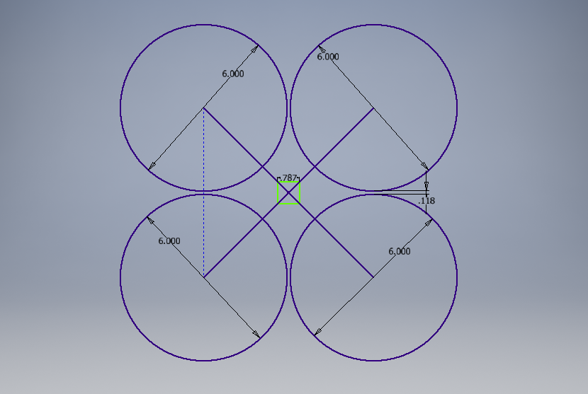
First thing I did was go to the nearby hobby shop and pick up a carbon rod. That's right, there is actually a rare brick and mortar hobby shop near my new residence. I bought a 0.157" (4mm) diameter hollow core carbon rod that claims a mass of 0.282 g/in. Using Inventor, I determined I would need two 8.652 in. long pieces to build a simple X style frame that has clearance for 6" props.

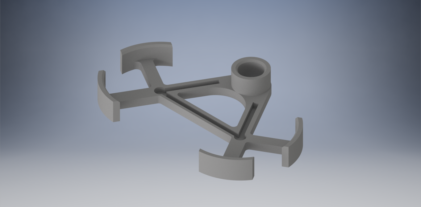
Continuing with Inventor, I designed the rest of the frame components. In order to minimize material use as much as possible, all the mounts are using 3 holes instead of 4. The motor mounts have a small clip that will snap on to the carbon rods (with glue), and hold the motor on with 3 bolts. To mount the flight controller and 4-in-1 ESC, I designed some simple collet style mounts. Basically some ring shaped pieces with a hole on the top to screw in an M2 bolt. The bolts will pass through the FC and ESC, and the two boards spaced by a thin piece of material. Once again only using 3 bolts not 4. Finally, the battery mounts are a little more interesting. They are designed to hold two 18650b batteries in series. The batteries will not be in a pack, but separate when removed from the frame. The battery mounts hold each battery at 3 different points, on each end of the battery. They also have thin grooves where the power wiring will reside. The ends of the batteries will make contact with exposed points to form the circuit, much like installing AA batteries in a holder. As a result, the batteries will be installed, rather than plugged in. The hovering quad will draw less than 1 amp, so the power wires can be small.

EnduranceQuad.png


EnduranceQuadLayout.png


Mounts.png


BatteryClip.png


I made a spreadsheet to keep track of all the parts and weights. I was able to find the mass of each purchased component on their respective product pages, and from the CAD I was able to determine the approximate mass of each fabricated part. Altogether, I am looking at a projected mass of 179 g. That does not include the mass of the wiring (additional to what comes with the motors and FC) and glue. In order to meet the mass used for the ecalc calculations, I need to stay below 186 g.

Parts.png
 

Snarls

Gravity Tester
Mentor
I've been working on constructing the frame. It's been a really quick build so far, but I've only been working on it here and there. There is no rush since the banggood order is out in the ether somewhere.

Making the basic frame involved first cutting two 8.652 inch lengths of carbon rod. Correspondingly, this is just a tad larger than a 220 mm sized frame, with 6 inch props. I located the center of each carbon rod and used a metal file to cut in slots with a depth equal to half the diameter of the rod, and a width equal to the diameter of the rod. The result is just a lap joint between the two carbon rods. This will allow me to build a '+' style shape with the two carbon rods on the same plane, as opposed to one on top of the other. It will be easier and require less material to bond the two rods together.

Rods1.jpg


Rods2.jpg


Rods3.jpg


I also have been testing prints of the motor mounts and flight stack mounts. Mainly, I am just checking the fit of each piece on the carbon rod. I initially sized the diameter of the clip/hole to be slightly larger than the stated diameter of the carbon rod, but this turned out to be too loose of a fit. I switched to specifying the clip/hole to be equal to the diameter of the carbon rod (4mm), and the fit is much more snug and rigid.

TestParts.jpg
 

Snarls

Gravity Tester
Mentor
To aid in the construction of the frame, I designed and printed a jig to hold the carbon rods perpendicularly to each other. The jig keeps this angular alignment, and also frees up my hands to work on bonding the two carbon rods together.

The bonding was done with CA soaked sewing thread wrapped in a cross pattern over both carbon rods. I got the idea for this method from RCTestFlight, who used it to build a heavy lift octocopter a few years ago. It is a very lightweight bonding method, and it is strong enough for my purposes.

FrameJig.jpg


FrameWrapped.jpg


After testing the fit of all 3D printed pieces, I went ahead and printed the full set of parts needed to build out the frame.

FrameParts.jpg


All up, the frame is around 9 g, which is over the 7 g predicted in my calculations. Notably, it is hard to be precise with a kitchen scale that only reads in 1 g increments. The carbon rods are approximately 6 g, versus the 5 g predicted, and the 3D printed parts are around 3 g, versus the 2 g predicted. I am hoping there will be areas of the build to cut weight, so that I can make up for deviations that I am already seeing from the theoritical values.
 

quorneng

Master member
I am not sure your "lap joint" frame is such a good idea.
The maximum bending load and thus the likely point of failure in such a structure is at the centre, yet you have cut half its thickness away. Any strength restored by the glue will only have a small fraction of the original strength of the carbon rod.
It could be that the joint will prove to be 'good enough' but that then raises the question how much over strength and weight is the rest of the X frame.
If you really want to create the best possible strength to weight ratio you may have to abandon the convenience of a simple carbon rods and perhaps consider some form of structure that puts every part at the same level of stress.
An "X" with thick arms at the centre tapering out towards the motor mounts is a much better shape to combine light weight and stiffness, indeed quite a few quad bodies already do this.

Saving weight in any flying structure is to be applauded but remember as a 'rule of thumb' each additional weight percentage saved is likely to require twice as much effort to achieve!
 

Snarls

Gravity Tester
Mentor
I completely agree that a more ideal frame could be designed and made with more time and effort. What I have now is what I think is the best I can achieve with the materials and tools available. As for the lap joint, as you agree, I think the glue joint should still be more than enough for forces sustained in hover. For one of the rods, the missing carbon is replaced by not just glue, but the other carbon in compression. The other rod has the missing section in tension so it might as well be as strong as the glue and thread there.

I may consider building a more heavily engineered frame if I want to get even more flight time, it would certainly be a fun challenge. But it's important to remember that engineering is more than making the perfect design, its about making a solution within the time, budget, and capabilities you have. Of course, a pefect design would help me win this competition! :p
 

Snarls

Gravity Tester
Mentor
I've been working on the build this past week now that all the parts are in.

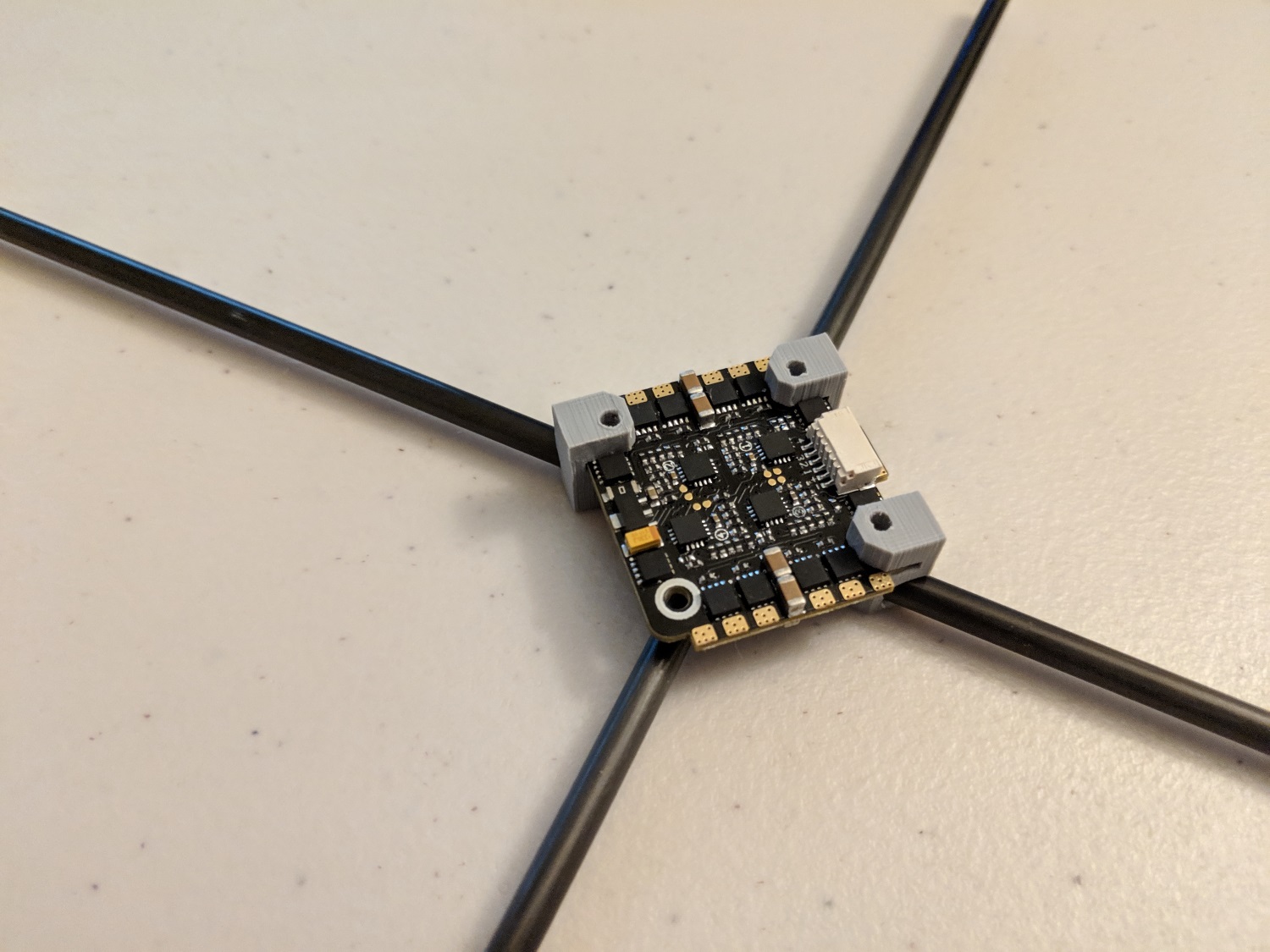
My original design for mounting the ESCs and flight controller was not working out too good. There was not enough material for adequate thread engagement on the nylon bolts, and it was very difficult to align the 4-in-1 ESC to the FC, with spacers, before putting the bolts in to secure it. To solve this, I designed a component that acts as a standoff and spacer at the same time, all while fitting on the carbon frame. It took a few tries to get the fit and alignment right, and it weighs a fair bit more than the original idea, but I ended up with a mounting method that is much easier to setup and work with.

StackClips.jpg


ESCInstall.jpg


Another thing I built was the holders for the 18650b batteries. The initial design was slightly too tight for fitting two batteries, and the curved pieces on the end of the 'arms' were not tall enough to constrain the batteries well. I increased the dimensions on both of those issues, and ended up with a pretty solid battery mounting system. This build integrates the inter-battery wiring into the battery holders. Instead of a 'pack' with a connector to plug in, it is like a AA battery compartment where you plug in two individual 18650bs and get a 2s configuration.

I used some nickel battery strip and small 28 AWG wires to make contacts for the batteries. One battery holder connects the positive of one battery to the negative of the other. The other battery holder contacts the beginning and end of the 2s chain, and will connect to the ESCs to give power.
BattClips.jpg
 

PsyBorg

Wake up! Time to fly!
That fc mount is genious. Should help structurally with the center frame.

How long left before the competition fly off?
 

Snarls

Gravity Tester
Mentor
Thanks Psyborg. The competition fly off doesn't really have a set date. The competition is with a college friend of mine, and we both have moved to different places. So meeting in person to fly is going to be a rare event. We will probably just film it all on video and/or take our word for the time we get. We haven't set a date to be done by because we are both busy with other projects. So its more like 'do it at some point and tell me what flight time you get, and I'll tell you mine when I get around to it' :p.

It also just snowed and below freezing temps have arrived so I think flying will have to be indoors.
 

PsyBorg

Wake up! Time to fly!
Yeah we got close to 6 inches lat night here too.

Not that I am remotly wanting to fly atm.

Bent over this morning to put in some pants and twinged something in my back. Just gettin to the point the spasms are lessening and I can stay in one position more then 30 seconds at a time.

Wanted to work on quads today myself but thats not gonna happen any time soon.
 

Snarls

Gravity Tester
Mentor
Time to break out the winter flying gear I guess. Last year, the with the new drone club at my school, we were having flying sessions in below freezing temps. It took coats, hats, gloves, face masks, and a hefty amount of conformal coat on our quads, but we made it work. The things you'll do to get away from school work :LOL:.
 

PsyBorg

Wake up! Time to fly!
Oh i know... every winter my butt was out flying as long as temp was over 40 to be nice to the batteries.

As long as it was not raining or snowing I was out freezing my fingers off.

On the bright side the slight resistance of the driving gloves improved precission and strength of the fingers.
 

Snarls

Gravity Tester
Mentor
I finished the rest of the physical build last night. With the battery mounts done, I could attach the motor mounts. They are glued in place, so I needed to make sure the fc/esc standoffs and battery mounts were good to go before doing this. To make all the motor mounts coplanar, I used four magnets I found to form an elevated plane with which the motor mounts could rest and align upon. They were then glued with CA into this position.


motormounts.jpg


With that, the frame was completed. All up it is only 9 g! Pretty good considering the 10 g budget I had for it. That said, my scale is not super accurate, especially at low values so it may be +- that value.
mass.jpg


The battery leads were then soldered to the bottom of the 4-in-1 ESC
bottom.jpg


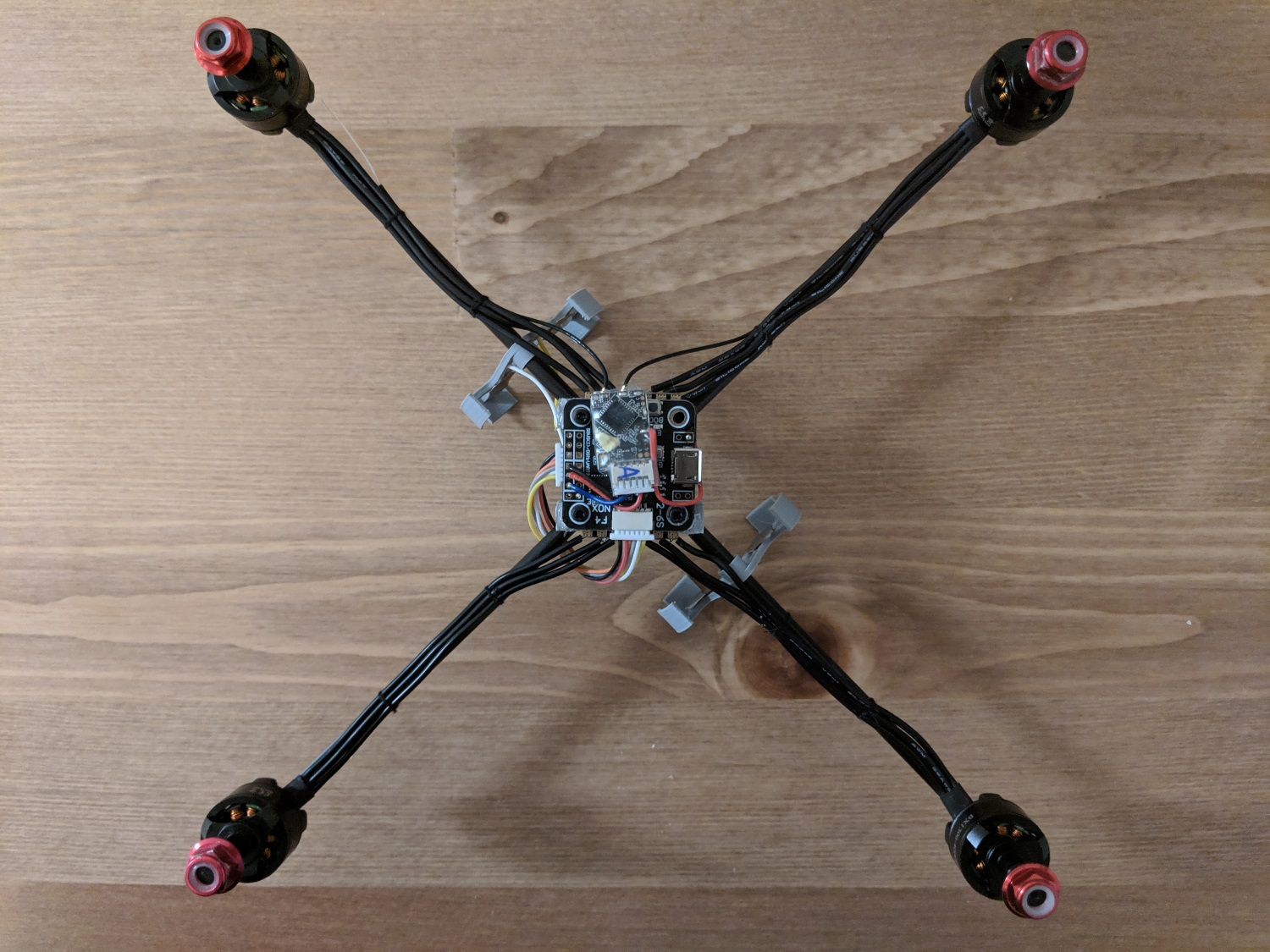
I attached the motors and spent some time cutting each motor wire to the right length, and then soldered them to the ESCs. To clean up the wires from moving loosely around, I used some sewing thread to bind the wiring to the carbon rods of the frame. In this picture, the bottom two arms of the frame have the wires tied up, and the top two are still loose.
wirewrap.jpg


The FC prep was probably the easiest I have ever done, but it still took some time. The FC connects to the 4-in-1 ESC using a wire harness that was provided, so only the receiver needed to be soldered. I am using an R-XSR with this F4 flight controller. It took some time, and some soldering and unsoldering to figure out if I should be using inverted sbus and smartport, or uninverted sbus and smartport. I ended up determining that inverted sbus and uninveted smartport is what works on this FC. The receiver is secured to the FC with just a drop of hot glue. I may be able to shave off another gram or two by removing the antennas. Since I am only going to be hovering within my vicinity, I think I can get away without them.

Configuring Betaflight was a little bit of trouble. I started by flashing the latest betaflight only to find that 'barometer' mode (altitude hold) has been removed since BF3.4. Apparently it does not work that well so they removed it. That is a bit disappointing since altitude hold is one of the easiest 'autonomous' control modes to implement. I guess the devs would rather focus on freestyle/racing developments, understandably. For now I am using 8k/8k loop times with dshot600. I may try stepping down to lower looptimes and dshot values to reduce CPU load, and hopefully associated power consumption.

Also worth mentioning that I will not be using a GPS to provide position hold for me. It turns out the GPS I have does not have a magnetometer, and using any non-integrated magnetometer requires tapping into the i2C pins on the FC. Unfortunately my FC, and every 20x20 FC with a barometer does not have the i2C pins exposed. To make things worse, the board I am using (F4 noxe) is not a supported iNav target anyway so I would have had to make a custom build. I blame myself for not doing enough research beforehand, but after looking into it, I don't think I can pull off a GPS enabled 20x20 size stack with any of the boards available out there. So for now I will be gently correcting the position of the quad in a hopefully working altitude hold.

fcwired.jpg


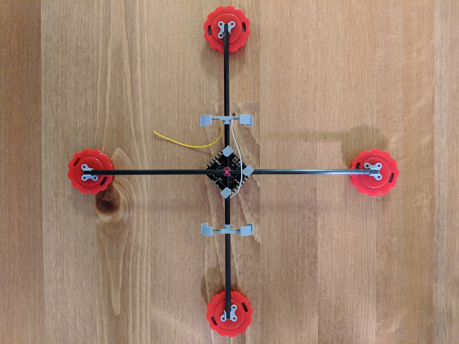
Here is is, all together. I just need to get the motor mapping right, and confirm everything is spinning in the right direction. This will be a + style configuration, the first I have ever done. The reason being that the mass of the batteries is evenly distributed in the + config compared to the X config. I chose the rear of the quad as the corner of the FC with no standoff (top right in this photo).
assembled.jpg


Maiden will likely be tonight, and the first endurance flight test will be this weekend! I think the 18650bs need to be broken in, so the first flights may not be the longest I can get.
 

Snarls

Gravity Tester
Mentor
I've had a couple flights since the last post. I had a scare last Friday trying to get the motors working. I was unable to arm, and motor 4 was not recognized by Betaflight nor Blheli configurator. I thought for a while that I had a bad ESC or wire going to the FC. The ESC calibrations were also way off, at like 1300-1500 instead of 1000-2000. After some searching I discovered that the motor resource mapping was wrong, and motor 4 was not even mapped! I had redone the resource mapping earlier, knowing my ESC numbers did not match the order expected by the FC, and that the FC is rotated 45 degrees. Somehow that did not save as intended, giving me bad mapping, and a missing motor. I corrected the mapping and all the motors were recognized. I was even able to arm. I still had the motors 90 degrees off, so I quickly redid the mapping to the correct values.

These first flights have been interesting. First, the quad is quiet enough to fly in my apartment. It's not super silent, but it's about the same as the AC vent or a small vacuum. The next thing I discovered is that betaflight altitude hold is, well, one of the worst things I've seen in betaflight. With the stock PID values, altitude hold just makes the quad jump higher and higher into the air. I had to lower the PIDs down to very low values to get this behavior to stop, but at that point it can not hold altitude. I'll have to take it outside and see if it can at least hold within a 1-2m span, as that would be good enough for me. For now I am flying all manual in autolevel.

These 18650b batteries I have are unfortunately disappointing so far. I can't quite blame the brand, or the type of battery yet though. They sag pretty bad, which is not surprising for batteries with 10A discharge max. At points I'm seeing the batteries sag to 3.2V and recover to 3.85V.

The biggest problem I'm facing is that at low voltages, when the batteries are around 6.1-6.2V total, the quad gets into an unstable slow oscillation, almost exclusively on the pitch axis. I also hear a squeaking sound, as if one of my props is loose. But my props aren't loose, and I think this noise is motor desync. Here's what I've tried so far. Changing motor timing does not seem to affect the desync, nor does demag compensation, and low power protection in blheli. I've also tried lowering the PIDs in case this is a PID related oscillation. I'm also thinking my battery mounting system is introducing a large contact resistance, causing my batteries to sag to a lower voltage, putting the motors in a state where desync occurs. To solve this, I build another battery mounting system with larger gauge wires and metal tabs that should more reliably contact a large area of the battery. Unfortunately this did not seem to make a difference. Right now I'm concerned the desync may be unavoidable at low (~6.0V) voltages, but I can't stay above that mark with what I'm flying with now. I may try using 5" biblades, triblades, and whatnot to see if these motors can not handle the inertia of the 6" biblades at these low voltages.

All said, my best flight time is 22 minutes so far, which is the longest I've ever flown any multirotor, but it is only 1/3 of what I am hoping to get. I'm going to keep pushing for better.