F/A-18 E Super Hornet SUPERSIZED 150%

HilldaFlyer

Well-known member
Hold me back... I'm doing it again.
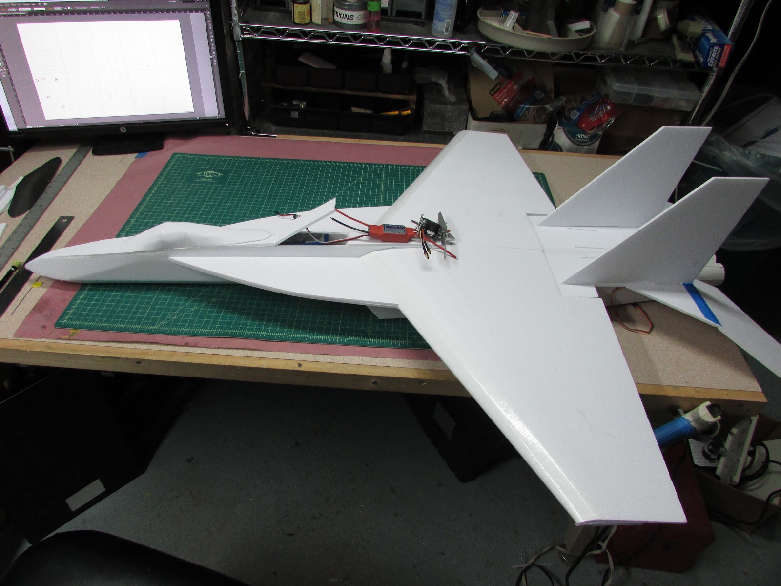
I have do say that bigger planes are a lot of fun. So, I enlarged the FT-18 plans just over 150%. Actually, the size was determined by the dimensions of the foam core. To maximize the width of the foam core, the plans were scaled up until the wing panels could barely fit. So, the SS F-18 has just under 100 cm wingspan.
KcDb89gDdz9b-shOQPnSCTxfSv-4-_nWXAuWdeZcS2W9C2EoujiukkvRHoY8Rnj-0dnZKtSyL-Prag8pyDtjRDwaqHNv0qiHv7CKrrXCjctJ_wQkBMSQAnB8NiOtZOWkwgFw--DX

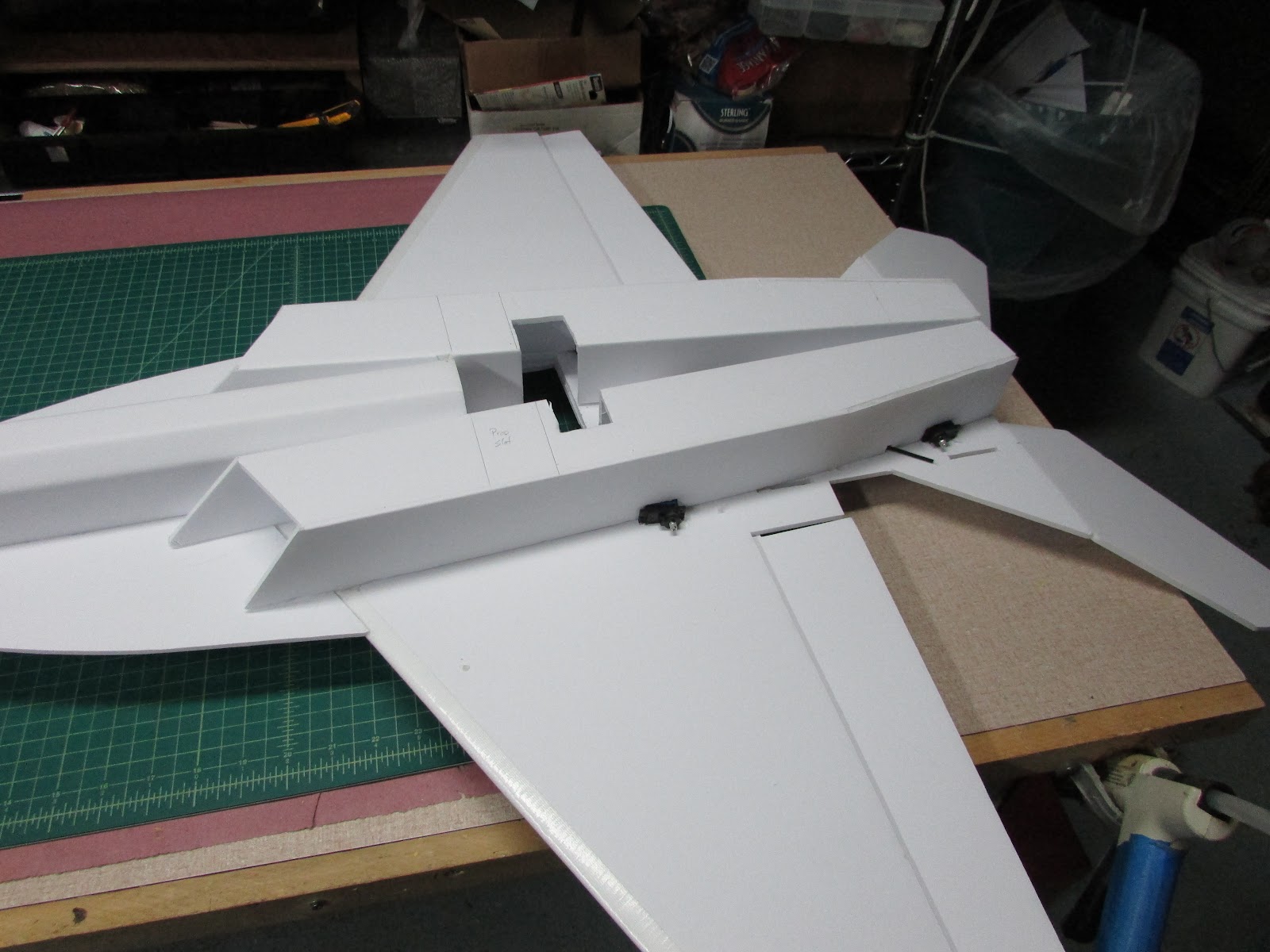
Here is a photo to wet your whistle. This plane sports airfoil wings
vUhH8fxNeNvLvRaSUO_k_poqhigLBsty8JC1frnxnimq13o4jVZSJSyR10UoiPiv-UO7teaxG_Ad9gv3RAHtjy6b-CFZBu7Zpd9i65DccPPW6mlEe2dy0zaAnWRqlbA9S82VLd3h

and engine nacelles.


HilldaFlyer

Well-known member
The Plans

First - I'll get this out of the way. I designed this build to be compatible with common FT build techniques. If it flies, I'm going to definitely make another with fiberglassed foam core. But for now, this will do. Also, I used Ross foam core from Walmart. It holds up against the humidity element better than Readi-Board.

The plane can be cut out of 4 sheets - but I typically use five.
DIXmlX8kQMi9ll3tAnOnsbXw06lfR76iyfx1KUUd8bU9VZGUEXKB1qnsiZdNqY9F7s8HgQBXjkTUYyTHX2HRzAYzbb_ZMxsF_sVqNS_VasKge7_EfU6bbNu9_kZweUXzpL2Is0k1


Oh, here are the plans: View attachment FA-18 ws40 Final Plans.pdf

I hope that worked...
 
Last edited:

HilldaFlyer

Well-known member
Wings

Cut out the wing panels. I know everyone has their own techniques. I lay the plans on the foam core and poke holes with a piece of sharpened music wire. Then I cut from dot-to-dot. Mark all the holes and crease lines with a hole... but only cut the perimeter leaving all tab holes, propeller and motor mount holes intact - these will be cut out later. The crease/bend lines for the airfoils only need to be made on the inside, the rest of them should be punctured through so they are visible after the wing is glued together. Oh, don't forget to mark the CG spot.

zZwYC3qhjm6obdz9Z2dQIUpW-Ob8VseOb7gc3JTOR8Y5zunIisNHH4y1Ne8ytgC4T1bvlW31u7cNWH1FLOkwcwl575tJOr0LqwlyjI8pwUNxuXMGf_jVasTjFpyLLT_ePu9gDA93

Crease the top wing panel - I use a tongue depressor. Make several light strokes without tearing the paper.

EndYApVXdByAtfRf1MokTxPJX41i1gZID9sCoUsVi2LAUorkn6wv3VpE7fay0FIsOYVzJ_GWqBul4PQQsQCFnJWZYKdSVVra2F_qlwcm4IcGNovp-TbBRRfezOeKWNi6AjJ8f7og

Lay the foam against a sharp edge and press with both hands to make a bend (my other hand is holding the camera). Then gently bend along the crease/bend until it has the general shape, like the wing panel in the background.


HilldaFlyer

Well-known member
Wing Spar

To make a spar, I don't follow the plan... say what?
For me it is too difficult to get two cuts to be exactly the same width. So, what I do is make a score cut in a piece of foam that is 50 cm long. I fold the foam back onto itself and then cut from 1 cm to 0.5 cm thick.
Kx9OSY6wxlaEZKmDPqDWe2iZ07v1IlEIHbYrM3xqMGuFRJNVJqVnPOi-3l6WLejF7ahlY1JTS8q2066aobTX56nk4odNAzP0yewzYXCek_J2khUY2PFjMEJRx6PhjOunPPRn2OPr

If you hold the knife perfectly perpendicular to the table, a spar is formed with both sides being held together with a paper hinge.

t2CgS5sDJdcDcnPsNX4Khp7Jc8H6loowrBusz3DT4BFSx005TCRxPBQS5aKmFs4DJOGrL9uONxwxV81SmIzLYIwXxCCZi28U_utqx1AgXgWVJQ5hxtg6--YbEciL7qSBVY_5vkoB

Add glue
CFAtZOba_5dABHLSgLjhFZmUHTCTCwvAJHgr8nThQ9PtsD8SBnxp19n6z_0Nw2YFvtj2KbPK5ol0m8BkIgAFXeW_bQ9L7Pf64GyVT1pK9elKn35ti2_O12w_cxahUW12jEXMTDQ8

and hold to a flat surface. Here I show hot glue (but I really used Gorilla Glue on the last build).
 

HilldaFlyer

Well-known member
Spar placement

I don't have any marks for the spar placement, except for the wing bends. I center the spar in the middle between the last two from the leading edge.
WoR-ziWgmUIt3hKR0gA9B5CXJlPDyqN-bZJpx0wNrRm6FuNNCEUJkkCzz3kQxKkKRmT_EiDIMYUhFyPE_Ycb-W5JzycpS9g31lxfsmPFksulX-kwPF72m3RfzYd3j3qcyUJTBUyZ

I tape it in place with masking tape,
IMg_4yUfS35mJYAXFv4wdJj86hgenFtfYmnWiC1wrfEnSCJ58Bb4Koftbqda-mTgEU2xZdJ6Q4_MaaqqyrXUmdvG_UaCatdiTry_ImbFSY2PmiJVn94XcM6h9FBGPD7eCFukmC5g

with the root hanging over a bit.

0Vncc9rVtW1YwcZPFqaAGsjjMdCx_lmZRLBp2yWHFkndk5pbNX88LhyaB1DJqWkvh0-_eyBA_DavuOG-XrflabOcg-KJ7OGwkCYTQbJhukFyC4N4LZF9u8FAa_FR-4ROmlQCcVhb

Then I roll the spar onto the tape, add glue and roll it back to the wing and hold it in place.
2zHyRPWA3S19Ww7JdUKPaL-eJ7FxK858W5WUecGnO0wQ4g78xA8Yf0s7xjvyH7HITh7WSidFRrvuU6-ytKj9yKsDH54UvxT7xLJqcORc9pfqZZwHq-fFr4qZF4Ou0UAaQIEKmnHT

When the glue is cured or cooled, cut the root parallel with the root edge.

Presto.. the top wing panel is done.
ty8Dh2wj2rm_tgp-UmEkXcOLNvlt7w8tlL2eIwZN_Q-XjGyczLMdhPp7dRMnE0xcviFd2nFnIPrBIctgTzgXVYVTkgOVkIttQ46QAyu69C9b2dRpeOyKND-QzntO8_E-uetcTBl9


HilldaFlyer

Well-known member
Join the wing panels

Joint the top and bottom wing panels together at the leading edge.
UYNhGPXi-PJ7jxkIzMwA1Bn-o_GeATXODxkbmo05zpF0ODHSRIGNTFeeId-9qCDKFYLL4dzL6Tswlm8TxvPzkO1tq59istC8LWrSV1u6KVSf1asw7MKjImx4rLSuJlJrvx2JXRR2

I use that awesome clear and really expensive clear duct tape. I have succeeded with 2 inch wide masking tape. Run a strip of tape along the leading edge of the bottom wing panel.

PSIemfb5s-WlyK5efYBVVPtnEt6jiGV3VfyYWEO5ZJx7OCavuIffsC-sFgmaTC9GoZD3LVMpVyogC2XmXcb7ZsWGqDO-64v5h_BD_9QJOaxtQANzLww9MVDL7Gw4dTJttFnUOv6U

Hold the top wing panel so the points at the root of the leading edges align. Press the top wing panel into the tape.


Ym5yE_-RwGY6RG5PtL3MC_YKW26jwxZGLPJpF8JKIX0GZCMN0wxGKzfweIaMm2tj8G8wrGqo-kJqOtf9qHG5zS7y2op55XIRzy_ljmu1dKl1UGVOZnKSIlE78X04hiaGIJVu_g0W

Slowly press the top wing panel into the bevel cut of the bottom wing panel and with your thumb press it into the tape. The leading edge of the top wing panel will slide down the bevel cut and get stuck in the tape. It should be a perfect fit.


1TLry6D26j9yfTKhM9dCb0XbnbfUONSQpTdDRIC9be8v2b81Pd9EGOE-vi5vwtUSTECrf0xAD1OneIFt2ETxPYVFFIu7rBOUTvdX3FtbtQrOnlBHKO0I9bQ3pIG1dCy_3kRoKPd1

Flip the wing over and lay the leading edge joint over the edge of your build table and finish pushing the tape onto the foam core.


HilldaFlyer

Well-known member
Join Left and Right wings

lCDKHipQmIoxrAbf5xyEIr9QFxdZU6rG4krX55OJjBc_Xh7Q-_pKVUo1jX_dq_QNrWnLn8zqOMst66dt8o9yaipVOLY8OwZKsKXkq2Sn_lubQRDcWc_vl0ESeDVG_76yf3sbhR2j

I like using Gorilla glue to join the wing panels together, but you can use hot glue if you want to. Use masking tape to hold the wing panels together making sure the edges of the tails are aligned.
of6-PVMk12lYBPeK8xTOxvb10a-sC8V1j4WzdoG8lgGMs0j-co09dCK5gPz0V8AoBqHZM3aD56GvtAlcb-4kE7Zcxo-mKyL0fWokAjLAgFTefxyfKOFXeeGRSM9wOyPAW1iLB2Kw

Once taped together, open the tape joint by lifting the center of the panels off the table and add Gorilla glue to the length between the two bottom panels and lay flat. Add Gorilla glue along the leading edge bevel cuts and along the length of the spars and along the edge of the top wing panel (marked in red). If you use hot glue, the same steps are followed only don’t try to do it all at once. Just make sure that the center of each top wing panel does not cross the center seam of the bottom panels and that the top wing panel is pressed into the spar.
IeRDpcePj7hY-H4uKAJZ7g-UMFv7j4e2QP165EsTicnLkoKKpaXKGDQb9XFyWV1IVMrZeTZoxqQYv73I5qZmNuk4WJrCzv2ne5OGmpL9V9e6qFGDWIq7V0oktUCTC7OXxVd9JAeA

Roll the top wing panels over the bottom wing panel that is laying on a flat surface and hold in place until the glue cures. If you are using Gorilla glue, I suggest using weights placed along the spar because it takes a few hours to set. The excess Gorilla glue that oozes out of the crack can be easily cut off with a one-sided razor blade or sanded off. After curing, remove the masking tape and if you want, the tape used to form the leading edge. Some people like leaving it on for added strength.


OidpqHQdi2Hc-XTW6sTmmqcFy6BZGM0Qvam8c9lCY_4JRd4EISqckFCxPEfhGuh0WDh4kAhmJRKXmHCN9nlFhI9xJuBQ832APd4A8oiPVFuKMh6UgNCEYMpScEnacbiE43OUnwLC

Next, cut out the fuselage tab holes in the bottom of the wing panel.
lukziB-osUg-QlzBlVE3rexrMSAObSDdMBx-n9kol6Tn7wQsiVw0CuOYrLdamHfldtGCiGSFFHyFZLro1rBEQCtoMSMOI3d-FsZRdnXP5WvlOWmpebb9DbnRGR3yKpr5ue2amvQV

While you are at it, you might as well cut the four tab holes for the engine nacelles.


HilldaFlyer

Well-known member
Making the Fuselage

FbwP0xELwXZfylOSN1Py7djbMfl7qMtqS5G5qNDcPz1zgDMmeekO94qXsWYGwJUcZUMacG9TBwDLWj_xtiWaLm2AhoZJcwjCEAJip_cyAP8-jDSZM1hZIkd2hwq1xLKuKyNoG9eb

Cut out the outline of the fuselage. I like using pinholes to mark the places along the plan lines and then cutting from dot to dot. For the nose cone area, I draw a line from dot to dot and then just freehand the cut along the lines. At this point all the pinholes are on one side of the board. Since some of the pinholes mark the location of wing slots and tab holes that will be cut later, they need to be on the outside of the fuselage after it is formed. The only pin holes that need to be on the inside of the fuselage are those that mark the crease/bend lines.
HCW2p7W1IhpawDOS3xpP5jjNkLTOmjaNlyILEWuwFtZF1QrK-kqlK3tzt_w6r-BIYZ1xSGOa4T4Jq47YkVuiKScA_L5m6o-KlVKC60mDgOjMu4JY8ey4IFpodutR2tA3z0iWEnhi

There are six holes on the rear of the fuselage and
8ERYAd4-c3SCSRzpxCboE0eUyMSTGWaWst_BeqnB-X6QRZN7PdTEJY4zT8VjIcviLBZre-mzSKOrT78KI-7CxUgXTA-qwQHUn5iNjAHLrtlyJS19B9dzin0n-4SHBN-0V4YVdijw

two holes near the nose cone that need to be punched through to the other side (marked in black above). After these pinholes are punched through, flip the foam core over so the side with all the pinholes is face down. Only the visible holes should be those marking the placement of the crease/bend lines.
1OriHqV9cAaX-mgBthhxexLyoYpOUBbNvC8M3yjHjeG6hYNnb0TbT4aHYSoXOtqKLyQjNgnhFPwV2w-9I7N7SyYfXbbH6UrvNrj8HxMx1q8DAajL6P_Ckhh5ktOTnJVo_ty7SnED

Crease along the lines (between the pinholes) with a popsicle stick.
HBA1uT42n3z-N2yqokbpxGYDN4QkWLtC4u-c9y4aIHyKG0cR98jB-5XdklEjRqLfGDstZsyeYxLST41-JGFXon4jTU3KlX70Olr9oPBp4YB9ywZu9Y32Bevy8pj_sNecawUFjote

It’s hard getting a photo of the crease lines, but this is what it should look like.
0fZow97zzrf13QaRmHVuQsYH5X-ls_RccsmLeE_ZDBbX3b5WCtZJJQe-5OQJmNduAkHBCaA0xWfWxMRPa4pWhBt-L3qwQbESN9DByGW05ZvEZDIGE98kSLASvCTnhnwWEOFanr1k

Cut a bevel along the inside edges of the fuselage nose points that will form the nose cone.
W4Rwple4scLnEFejAQDoz7QqSZD8aqLTfYy6pS0DiT9xC0w8TL88rtKlApZCFlxHkPi-k79Ke6YD7vx8pAsQ7gTW181OzeWlNqhSEbw90680TN_lWlUjSXt6U3iQVYTK5fZOO7Nz

Use the sharp edge of the build table to bend along the bottom four crease lines.
6fTVorj-8D-ztqWoLU473vUWgWMBuDOozSmEp0NymO_gyMZFcXDlOy2J9Pzzw91q37ovBCghIsfUShEyPMvbuHYbpIqBA8Y9LaWQgLcdveu4QyxleK916FBIXuVvzhfBpsRvGeAX

The bottom of the fuselage should bend into a “U” shape with the bottom being half of an octagon.
Bend the fuselage in the “U” shape and hold it with rubber bands. Add hot glue to the fuselage formers one at a time and put them in place by spreading the fuselage.
aRAEY1PoNG7I84mAf2Twb3ovMx77uf44sj5fKggayl3YJdifddw_4ObrfB0qV6Lw2yNjs_I6_QrLrM4oDrSsiJ1e2W5MpPCU59k2jsE4rfcebDn_yTQz5G7KvmssiLCcuBmgNWN8

While the glue is cooling, ensure the top of the “U” is flat by holding the fuselage upside down against the build table surface.
xlYnxlAGDP3bjjMRdaOYn-AoY2QvW9ToqPsycmEf2mypQQyFUNnkVvOB5BJf33NzOkRmGMicgmLtDH0nWvQCkXDxT4wPWwjSDKEiIxj46jZ-AW36wLzlQrcHs-UJUyujct4c8ohl

The formers should be placed every 8 cm starting from the rear of the fuselage.
QE-Bo--f_39GQYFHDo0VXzRFYxdNtH6l7hLoBoTQnpkNZyeEFSNMEkZZG676vogZcmR8TzM5cVCBPmkK8Lb__WuzTnZOgzQNOweiz7e3qjvL0pCRGoj3GpugGBbwm4hB6SYha2PI

The rear most former, a rectangle piece of foam, is added last and glued between the side cheeks of the fuselage anywhere from the octagon bend to halfway up the side cheeks. Any higher may block the wing from sliding into its slot. You’ll see how this all works a bit later.
 

HilldaFlyer

Well-known member
Forming the Nose cone

Before gluing the nose cone points,
7nslLFkDwWoli3bBLiQ7Z-HsX11nI253-Z71T4psg0KGx47KGzjjfkjGfOlxR3cy6aEZ42l6UFdhd9y6nCNY7mkaIlJXp2ZEalBlJuTdP1_0XuxgDrXKSTg829FBErKHX7AYDcfN

bend the nose cone side cheek panels. These are the creases that run from the first “V” to the canopy as marked above in blue.
op4W3J0_f0s-YwFousu41388UmUNnqk1Xke9ZKuzUqXcAIR-ZZ4mAnB3Tww_IJfz3nI5Rvbr8dIkId4fXG0ml3_0w-0U6LoveoXZ0PdqGdBX-E9SfryUaj4hHC20OAaoHeZw4b4Y

Crease and bend all the points so they arc towards each other.
zgEDFDVtixbloXBL4w9mFPasl5N6OpCExfMsCrlOEn6O3tXGGuEERL50Z1vTFSWz2LOWdjY7Mj4T3iDQHNrDzoxoovnbjUxGLs0EnoxNlsRwoDtBFAVNPMT_7GBBpH96_xB1MLgF

Glue the two side cheek points together.
QoXj8ws-tlIkfB2aTMKnX_dWlMybiXUGyhK1Nlxi7OqbOpz_yft-JIod8OzopIatV_XqhbkKB1UwxxXc62USReMOUAqryhwGxl6mLO4a4kfl-OhNnnFswl6FItVkyP85wyMehsSl

Then glue the points just below the side cheeks to the side cheek points on both sides. This takes a bit of pushing up on the lower point. Just hold it until the glue cools.
TRnjT7PHQFuD0UzwFIOLWzoO7NLgZiUcar7j0dwHoDKA-xXqlS2y3Lz_Mq50vcbO7W-X4vynZ6qtj4aR9KdFC2WCCDrs5kxkmPHa18brHM21CdrWH9vUVwOMH_hYnWUo4k11J91w

When both sides are glued, the bottom most point is glued to both sides.
vOuIiV901M_ugerxYObtUxi9e6CPvh4tIrVYGpljVcRFbWTIHI7XbRMBwOOZFvzV0X0N5AtK8bRyN2znxvaljlBD_uOHraSmIt2NRttaTjpVGIQxpdmpDNVva_Y9uDKhv9jwchDC

The nose cone is complete.
I know that looked easy... but this was my 6th one. I think the 5th went much better... but I didn't get pictures of it.
 

HilldaFlyer

Well-known member
Finishing the Fuselage

Battery Tray Platform
The next step is to add the battery tray platform to the top of the fuselage formers. Since the battery is used to adjust the balance of the plane to the CG, I like keeping my options open as to where the battery is placed until the end. After the fuselage is formed, the battery tray is glued to the battery tray platform.
YaYzgNU0zjse7UuofqynFbalxFU5_xu9dBj9py7OmqbKT7sentXJ2Xg8cltHY5guKvaL-005i2xFu4sFN1mupkMMPYGApYeCE_4b8Si_4OG_COXb2Huf_CM79G0CExfBJQGob0Jb

The platform is a flat 5cm by 25 cm piece of foam core (bottom) that is glued from the front point of the wing (marked by pencil below).
TqdGCdKEBVKd7l6d2kXoByZjAJ9rYpzNRSgPpEti-ZWW7jN9x4ivWWBW2ZIOmTOOu5pZZyzQDelcZ8YeXVPgImAHlRkln4k1JwV-vgkHF__dbLtHf1r8Ai4WLitm21rpkZYw60cr

UHVBOV-0WsTQqv94W6oIptAgAgLv3VUAF5FSxHUV2NWaiAqbTgCPNiBUKyELfWAZLP4DEabJhpI4BGiUWwSsrYf0Fk3i7hMth9_90IW9g8gF3b-zlRvJFDpbbX0-Oiy3XBqUM1i1

The battery tray will be added after the model is complete, but it is made by folding the piece back onto itself along the lines marked on the plan and adding velcro to hold the battery. The battery tray is positioned along the platform to balance the aircraft. It can be shortened to the length of your battery.
BykWxN8buO7ja56ub0LD0raFW3EJ_mk_m_lXixRia1aIOxZeDrZzoXEtkBTfpiEtM-P1tCoAhELha9Q4KSQ3i0oJo3N0kznMjkC-oXOsiqB16-nxXl3kK51Z1mvZVgWLmXH15bXq

Here is a picture of the battery tray platform with the battery tray moved forward. For this build the balance point was achieved by gluing the battery tray to the battery tray platform 8 cm forward of the wing leading edge point. You should finish the build and then glue the battery tray to the battery tray platform at the location to balance your plane.
PWq8TeniMPowBbNj7VxYJPzL_h8EreD_-BOC3GqaABE31hW-oXTgIcjpnSSa2lxPO9JABvwKEmk4r85wOU6rIFRteumzO6PWJebCCeEWvfHTa3GKkEJIxbJLoehUwXyg-U4_MMsb

Next, cut out the wing slots. With your hands, bend along the top most crease/bend line that extends from the wing cutout to underneath the canopy location so the the fuselage top piece fits. When it fits together comfortably, it is ready to be glued.
lVypDW4HAxEewh_22YrN66fPiwgwjhFGedWy3Kq2y8eXUOtcSaX9YZBU5-5CELv2-lWw84KH8mbho62LgziU9ZuEm0sbImKVbHqdg2PFNWlNdjHmMioZ-eCW6XTJX8Mw6RWPwSAC

Glue the fuselage top panel to the fuselage starting at the rear. Add hot glue to the top edges of the fuselage “U” from the rear to the marks for the battery hatch cover (which is the marked above). Do not glue along the length of the battery hatch cover (from the front of the wing to the battery hatch hinge).
unDkEjILUW2PZWZlN_2QEZkpr6IGAjsBcEPdHxEIPnegn8qvQnkDBmi9US_nKE6Tfj2WnH6gTDENsbBWl1MOESQ_4UzZSBh9vmaGMwHTmhXghDbYgvJkq4ywjdo6cS6YQGLM9S9Y

Continue to work your way forward by gluing the fuselage top panel to the fuselage from the battery hatch hinge to underneath the location of the canopy. The last step is to glue from underneath the canopy to the nose. To get glue between these pieces, I lift the fuselage top piece, add glue and then hold it in place.
KuMhL7GRKKLPfw_c5Y8eqJelu9MXCHZb08PhkmYc-94vZ8gAH2pXk_o1g10OX5du-FAImCmKggYWqNsQVl-Mv7u1g0KlMQYCiAEbqlyn6CT16ZWZ5Xa7LBG6po42RPIqULuDEI3D

The last step is to make the battery hatch work. In the rear, I but it at an angle to to make a jam. The hatch is held shut by gluing a couple of pieces of scrap foam to the underside of the hatch and then poking a toothpick through the side cheeks
 

HilldaFlyer

Well-known member
The Canopy

It only took, like, a hundred tries...
fdcDfkrxKej5LJMuQDNmfUbfkkmop2bEQ14UaztNYyHt3TQMLfgmJB6agDxUiCvUSfX5s2YCW0CfVOXa5HjLfBE5HmxTcnvFnNGfKHWHuJ45s4kY-QkjpPNXEPsIQH66V60A9R_3


to get the canopy to be the way I wanted.

kmOqH3_WglO2LjIIFSuRe2_VkXQ7LgvDFYgcVjmSfmrQiBEXedO8V8TjakfkkTj7hLKBXueC6CvB4S370ONlbMAYcPRjJcPOU9WHDHF86staXd4-hGTHjCJn_pltDkes76zCWnvS

Cut out the canopy piece and peel the paper off of one side which will become the inside.
gQmK05mL732wjJMsegrboJCm7t9tc8zQGW6p1LZdczZKv0-jdYNsYqKFshPfVyYkcJxeFw5p-xwQmPvI7azwAL9miUKg9u8fxl92sX0ivuvXQPsXLvCOQNUHzpVcP01NS9q_M9jG

Gently bend the canopy and massage it into a nice curvy shape.
FeQdoaPmc4TdSN9wIbxd4lPjHIDAh2P7W-gcQGYJFeq-Waev8wJybUm2MMSHwd4cqf6QWFAYGr0tSGQ83at8lXvSCgQHdyycuK8lGQyzSTEPcXxT1YTqMakDUDwN7LsvDG2se_mT

Add glue to the notch and push it together. Hold it until the glue completely cools.

TNkPDu-r7uKVkYK4bf5otGjs2H_JawS1QD2T-KxPBDTA3y0gJMDMYzBBTdKO7IlUti42rrkc0E02NzvFUANguK5GN0qwdC5sWFlqm1GKBq3dhucyL0AawtuGULtyG7TRB8UBwkKI

At this point the canopy has a general shape, but it is really hard to hold the curve while gluing it to the fuselage. To help me I use some rough formers. Cut four pieces of scrap foam with the lengths of 4, 4.2, 3.7 and 3.0 cm long.
EoJInWSHEHRx0SV0E2aemEg1mwJpx9ZHhSxpuBKZrP8GRnldsxGUZamgY9600Ut-VfUSe5K9PbjhieGZD0O8XKsZGkxCcP5ZIzS4XKCCOsJTP6uQCcQUfYKkxq1Pc7zSMobow3Iy

Glue the pieces of foam into the canopy as shown above to hold it in the curved shape.
fMhmQnPCo1PSY_-cCoKzrba7VKRyTPr09oMGb7jaF5bDrrliK34VazC6GVqsfkJCkWnCBuN2hvKpB7fGzsly4COkPq12E9zdl3wDx-ghHjjAm6RfapFnddgwVwowaPACE9PuOoWE

The bottom edge of the canopy needs to be flat. Lay a piece of sandpaper on the edge of the build table and sand the front and rear points. The canopy can be glued to the fuselage now or later.
IzG7LE16txta4szpymlwlwMqZLquIcpL4A7iqnKqaja8S4l5Z35mCQdwFmhx-2vudkOXIqM_qoFfBqw-yU09Ku5e3Tbx9CD0orC3lsN2ASy43-52tLW7HSgynuYFWAJdXw7WXbZh

The position of the canopy is placed on the fuselage so that rear point meets the battery hinge as shown above.
1b6bLg1DDX1ZNv91W21bM3dphgF57uFf97jxtZEW23iWIjydENM3pUm35er_KdSwaH8cUwj_tQHGNozKzV3sjN2gWtKd2PW0p40WX9KWWjBXDbBeZAY7d6NNgT11GY3dvvb2KcRW

It can be attached now or at the very end of the build.
 

HilldaFlyer

Well-known member
Leading Edge Extensions

J8dafizerm7y3f6TJ_TKOIFOgX54O_dIHcQ6KRBMJAwDkoKcWoMOmJDxs7sOMiddYwyxw5TLhukJYXkyTAwKv2ZINz8MjN4biEFoLpqAvYdMakZpO0puwItXdPM9r8EMXWUHKWMc

Cut out and bevel the rear of the leading edge extensions, the edge that will mesh with the wing. There should be four of these, the two bottom panels will have tabs and two top panels should not have tabs.
Zy3OIwSmv5XqXeoCSuT5JZ7ONci6ITOJghdi59GQOp6blUEH8d2ctcDY0BkmcR6GrTTdLodk5_r5CCLkFJr-m6qHLdtLyDxEro5fmBYk6pnctFttRV6zZa24mnE071_ApAI82CaV

The bottom panels with the tabs should be beveled up and the top panels beveled down so that when they are glued face to face they form a “V” for engaging the leading edge of the wing. Put them aside for a few minutes.

 
Last edited:

HilldaFlyer

Well-known member
Engine Nacelles

Build the nacelles by cutting them out and gluing them together using a “B” fold
ULXU0FUEIu_YpMqEY2H485obGAykxfPEYgDkcEOYEF_CNqI83AbIyEnh3TXYVy1H7OocQ_ruyvXtJbUiUScWIezc8PS9BEFPvZEr7Hfkw5vyvUR5AidTrewLEhn1LbLaEbS8gmzO


e8VvR6Q_rzi5N4Ghl0K4aYeb2s59M-45C_AiwPM2M66fXXECzRSfdL5WNS3sYyG8HEnP5WaJTmk2ftnvvgTbEdJT6DH1UboGM0QKLXfLfjNCNyrN-yfjyhR51H935XmQrWtd9RwB

The restriction portion to the rear can be glued together.
9wCAq8q4dcfk29dbAWqvlfJgEvDyIBQm261IW32UlMNMsjIgTrdqrO2El_KruLPwMDwI2ZnM3MokiyopANH1hb9iBi3qLso0ufHQ2vbFXFRv-_ht4-DPguz1D085Xy-bReAstILh

Test fit them to the underside of the wing (do not glue at this point, just make sure they fit).


HilldaFlyer

Well-known member
Fitting the Wings and Fuselage

H0YsmePXnSpgGRNPDVlz0k8sFu4X11X7K1pzw_8GQNzqC_FBuJY3nMGB75ok5b0byX8VLOhSDOlK_ecOUeG5UVvCh_c93XFu50CNg2i5KiVrhqtsCrSHdc9txmzva-JQy3gZxdm_

Cut out the motor and propeller holes that are marked on the top wing panel. At this point if you did not punch those marks through to the outside, you'll be wishing you had. Using a poking tool, mark the edges of the propeller slot through the bottom wing panel and cut it out.
zKRipQevl4DS7cfpqzz7z0GAPqf2yUqdHGTrIQNEOXWtKou_dveI6LDfBArBaMWt9aUAIFIFguvKKb08tk6s5P0Ivhd7HCaureTnain_FEqVtBMBQVCOkuJeDFAGSSkKf2DcPW56

Glue in the motor mount. In this design the motor mount was an FT- Elements plan that I cut out of ⅛ inch plywood on the sides and bottom and ¼ inch plywood for the motor side. The front of the motor mount slides under the wing panel and abuts the spar.
K7WRwqGwc-JA1_LiYEW4s2JYV_JDdVH5_zKh-uNuSM-F-IO6Rnex_80QLcT0tGZa8_D86Azl86-VlzC_FF5MB9XzTXkSBPHjwE_Hx0LYopXw_93Jpv517QInwNi1OtC91eQWCPzW

The motor wires feed through the bottom wing panel. I glue the ESC to the front of the bottom wing panel between the two fuselage tab holes as shown.
BjWBjDFfQEvW3GLFRSMf2-4NejAZpZhJrYuQ51E-uZ0ZRXbJ9yHD_opWOLvmckmKUOqOAiEmUJPPm0tPGphIFbOhrV23QyooxYq2SPHw3YZ7oco0YZhScgRjQxLrG5XNQQEKDQ3K

When the wing is slid into the fuselage the ESC will slide by the rear fuselage former.
QOPowesDZAotea_Hito-z_z83Gp_ngp7FWpiAZAaWSe0jCmOIgkMmM6qamQ_k73L56MvQFsEs_-Uua2c9vVmgfjm8fu_FaCHqz1iKvVfxNN7lm81ecdz3x28SIW5SRVmNnW_T4jq

Cut the ESC Cooling holes in both sides of the fuselage. With all the pieces in place, it should test fit as above. The nacelles cover the cooling holes pretty nicely. One advantage to this design of having all electronics attached to the wing (that I haven’t tested yet) is that after a bad nose crash, the fuselage can be cut off and a new one installed without touching the wings or electronics. - bonus! An alternative design that I did not pursue would be to mount the motor on a flat plate glued to the rear of the fuselage. This design would be more sleek since it would not have the motor mount sticking up through the top of the wing. Maybe I’ll try it next time.
rEYq6gbsZ5YDOgO-OnyQ7P5vJCctDhNCMGwT4YVo-zTAXx058W07Cv2s2Oi8TaC0YlzB-5EIy2HdpFMXqqQv3zO7MmdNNGHzYoSa0uY-TSLKpbCSIfpxXd0ydBaAMPicCOvervKz

With the fuselage wing tabs engaged in the wing, the bottom leading edge extensions should fit into their tab holes in the fuselage and meet the underside of the wing’s leading edge.
When all the pieces fit properly, it’s time to start gluing it together.


HilldaFlyer

Well-known member
Attaching the Wings to the Fuselage

PtGGjQp4ep61BT5L1xKdwMaG-iqyNpqPehpG4eOz056RzqYrw8LUxtWz558fSnSQkvEAdTOgiLQOHB_iUWYBJfO43tXfZgGPjdRStyyKRDV2Uv3JTJxWZDKEliyk2Nk-B791Rn7M

Start by glueing the leading edge extensions to the fuselage. These become the guides to get the main wings on straight.


Glue the fuselage to the wing
XP-z9NmPjSSCPpsRDAHUkqVNM5WvGsb-AYPHEA-vmR2z7yYLWzg2Def-Hh62ZaPCZ-nlW6iTuZ35WFH7FnMBr1TkgwLY0yFiz2HJgbxIAR2gBq7Yb1NOiaMnjbm0Y-UF5MXtofwm

Slide the wing into the wing slot and make sure the tabs on the bottom wing panel are fully engaged with the fuselage tabs. Make sure the wing is pushed all the way forward into the leading edge extensions and that the both leading edge extensions are flush with the wing’s leading edges. Without moving the alignment, hold the fuselage tight against the bottom of the wing and run bead of glue along the fuselage/wing joint on both sides. After it is cooled flip it over and glue the fuselage to the top of the wing.
Glue the leading edge extensions to the wing
X75YXD_3IbGqpizz46EVUH3I64pEHEZAUZjLIdPXcNFj-3CdI9t83LeXyT9XtAj86WyBsE0PdTni0j8mdl1szNC0REOL2QytZN_eBIIwtieLw1tmYO3LQ1h282hc0229y6H1h6d6

Push the leading edge extensions down a bit and add hot glue to both the left and right sides. Lift both leading edge extensions making sure that they run smoothly along the underside of the wing.
rEDh-Oj4Y-cw17pGFafOqVAKTa-1Ev0nc_E4DL8nt4g5LEZT-BXxD5rbd8581kNCovbhFmWcI0opbEyg22ZC7wyx3evDbi1rp3O2qc149nJdpe1bAyod2AIkgMz5JTMFk23fB9Ul

The top leading edge extension can be glued. If you use Ross foam core, you can use a water based glue like Elmer’s. Hot glue will work, but I would suggest warming the panels with a hair dryer so the glue stays pliable longer. Since this is basically decoration, it can be glued with a single bead around the edges.
AmXnvy_oeOUcsd6sbSpSP-WILu6Ng_mCs3dTbwdYHiUL5pOnBh9R-cNV7PBSve17G2_q002_999o5MiRmfOwAefZFnCQQNZ741Nw3F1Zc8WnOnbZlVVvRfjrnySBFBSwInZUUEtn

The end result should look like this.


HilldaFlyer

Well-known member
Electronic placement

Almost all of the electronics are hidden within the engine nacelles.
8E21J_BbBa78_3Hqb0Zf7A7pQefn2I0wVlOx1F1xz_eeVvZJnKO5iWzZbklimdg8rWQruRGs-xEWtEMN2tnRGYAtIWgJpjdZMh7TNrQ5i16tC2kHHSYAa6j3O0ydhcDd8MJPvVo-

With the nacelle in place, mark the location and position of the servos and draw a line along the inside nacelle panel to help locate the receiver location. Also, mark the location of cutouts for the servo wires.
O64T0hbp8gYG-5nA8wepVs6z1vek-3zZSwYoFVVxwwNykKINwDQvgTm16IPLn_24zTkAjtwQNSt0yRNIyLM25niywgJUwox7ZV9Gip4oMGrBKVXapz__rx-6BLF8ieWSf1Tf86Qr

Lift the nacelles out of the way and glue the servos in place. I tac down the servo wires with hot glue and paper over the top to hold them in place. I use coffee stir straws to hold the receiver antenna in place. Cut notches in the nacelles at all of the locations where wires and antenna travers the nacelle/wing joint. When you’ve got everything in place, now is a great time to hook up a battery and make sure the motor spins the correct direction and the servos are centered. I will share with you a piece of advice that I learned the hard way. The wire running past the propeller needs to be kept out of the propeller. Running the ESC control wire across the propeller notch as you see it above is dangerous because it is so close to the propeller. It is just setting there. After I glue the nacelles in place I move the wire and attach it to the furthest corner of the nacelle away from the propeller. Make sure the wire crossing the propeller notch is well secured.
Glue the nacelles in place
d_1_5Q_fUNAC_q62yCVc9up8MxBZSAHGp7Xs1eHaDFrQu7o5ckgTwxBO4HQrt0XL6h2fxNkaUGgLOc1jDQkr1Z5C2lt47cbL0olfI-EgMVW6naYAN6vy41hbM9NZOTRy2WTgd0W8

Practice fitting the nacelles to the wing a couple of times. Run a bead of glue down the inside edge of the nacelle and hold it in place. To glue the outside edge, I lift it up a bit off the wing and run a bead of glue underneath it and then press it back into place. With the nacelles in glued in place, finish cutting out the propeller hole in the nacelles so that the propeller slot matches the wing. The plans are marked with the approximate placement but can be altered to fit your desires. My ESC control wire is glued in place to the far left corner of the nacelle to give it a few more cm distance from that wire cutting-propeller.


HilldaFlyer

Well-known member
Elevator or Elevon attachment

DKk117iRKLakMqu1cW6CHRrAQmFDQULM3A0zEuhicaomDR2a7sovJnrBfqUMan0bLdoxf2R_4ee-3b-66BRz-kNFvbikYq5rzioGeoK1z4v6bVuqOF6TjrPgKWDhRj11KdQA3i6s

I secure the control surfaces to the plane with masking tape and use polyester cloth to make a “X” hinge.
Tu_MGC73JxCLlpYgP1r2Yb9UNQG0clUY92sOCvzke7eXEU0PwhPgOKEEq5pllkxhrsR-NqcoN0tVBmxI4N0w2XS_LtW7cqhzN2a2jSCgrVORAnDS71axPZQ7E3mJroPLSGgm27eh

Well, as luck would have it, the tail is a bit flimsy to hold the elevons. The model slipped off the table and hit the ground… and the tail folded. So, I added some wood to strengthen the tail.
Connect control rods from the servos to the ailerons and elevons.


HilldaFlyer

Well-known member
Vertical Stabilizers

GL5yz2q540TNake8sb9_szGXP6BaQEHXaO3CZt5zOF9XqBGF9dWClFZUb-Ge_jZvEb-y2j9sIen7DG-AWe0rU8rT75YOAuh6swhHoDcrNwJyyVPLwnkI8ROdeHCPb1FnDKEIu-73

To make a nice flush joint with the tail, bevel cut along the inside of the vertical stabilizer. Also, if you want to round the leading edge, now is a great time to so that. Glue them into the tab holes using the angle template to hold the proper angle.
fuEFHQc6jlQlApx664TQ4cYSu568aOPQnykGWDzdpipAdcVXCuS9XW9FxTKk1xb8G7v5tLY-6ZPYoFri01oH8LDWXCHlhIQOgAj1VC6F5ru1xCr09nj1neIfkEMyAs8eR_0LvxV8

Like the Supersized FT-22, I think the vertical stabilizers should be reinforced to prevent them from folding during flight. I used a skewer to poke a hole through foam board at the front of the stabilizers and
fkvrNOJhsO083fhcuc8i7bilTpuA0S-ldYcLNtLUWCIZZCF-sHa6bdznrhSuq9EuaZNElyIxZ419fCgtzUQ-b8EBPOIzAAG0NHGIvP8qZLHeTe7qYj6eXjzCuUwpMt6KrPIeEjkR

continue the hole through the nacelles.
dpOoRdXJzG3zZJvSFSYpHI3NTQ-xENVUvzM1eszXmqrAVG21dIlnj2VGiZgZQI4LkJv812B_HPUmkhqnj-bYh2OU0QQUjK3KZRGw0wq1SU-xnC27387kqVrYC1PddO8P2-PbQvOU

I used a 3 mm carbon fiber tube for this, but anything long and skinny would probably work - so if you don’t have carbon tube, use a skewer.


HilldaFlyer

Well-known member
Engine Nozzles

ZcLvCO9xv7lO1jHl3bC-01izXds31s30UrcY4KwoWiIn2cQHOEED75_sS2mN3BGVgNJNynEnKQR95N148o8Du70tHiTjs5f2503LAwPUBC35RJtwsETVOaCSvWxTfW4OzcxqU2q8

Cut the exhaust nozzles from card stock.
6ILfZ9aJ65D0z8x1qndl7KLobbg6YUHJwMgRjapotlztJ2ruBiFmpwxQ0dv10BaPu5mBxxvi68RWikDbpHgm1bb8Vp1Y3zoo1LhOfzJE4zRDWH0BZgBlorRsjtsXpBj65wuQ52ob

Cut along the solid lines and then roll into a circle and glue along the dotted line (the little tab should be the only thing holding it in a circle).
wzDuio9z1J_38akRIVORUASKO_qa10qfBDpsY9VweERySA0c1CDL_KnGiH6s5vnldWygYYamSrt5_7SJuhVCB_8fmZyZArAHQORV3f7x2T_TBKSNSiynjGTNfAUa50ZCEwNhWQeL

Glue the rear nozzle overlapping each segment by 1 cm. These can be squeezed into the square nacelles.
r3V5IGRE2rZaao-kplfxfhpXJHUnTZ-VLMDJg--Qzcw6lA32EqG-ZCOloBjiZaTUTRBklSJY3FqBAHtgyERYAfwb9gw-ZDtbmKievPE6JjjpsTaTVxQohr5A7BqHt59mjmt6c7cJ

Paint them black and then glue the exhaust nozzles into the nacelles by sliding them into the nacelle,
4kHRo6Yts6kpq9ncrzj5eblh5lwENld3Gj784XhWL16a7zdshaztBpJK18IURNxh88EAbZrHjZlWnSEYsfwqoJ0gFLcHlYbjvbKpguW-3Z46Jwjv0P1UxAFmc77bNwYB6_1qktcB

run a bead of glue around the engine nozzles and slide them into place.