
You are using an out of date browser. It may not display this or other websites correctly.
You should upgrade or use an alternative browser.
You should upgrade or use an alternative browser.
FF2017 Int. Racers: Crosby CR-4
- Thread starter HilldaFlyer
- Start date
HilldaFlyer
Well-known member
New Beginnings... Starting over
Well folks, if you have been following this thread, you know that I crashed out.
Time to start again.
After a short respite, I’ve redesigned the Crosby to take on the more traditional FliteTest techniques. The fuselage will be square with rounding formers on the top. The wings will be removable with no landing gear.

The first build will be made with Ross foam core. If it flies well, I’ll probably make another and skin it with fiberglass. The main reason for having removable wings is to try different lengths. The wings in the plans right now are to scale, but you all know how the last flight went, so I may want to increase wing area in order to increase stable flight characteristics.
The build starts this week.
Well folks, if you have been following this thread, you know that I crashed out.
Time to start again.
After a short respite, I’ve redesigned the Crosby to take on the more traditional FliteTest techniques. The fuselage will be square with rounding formers on the top. The wings will be removable with no landing gear.
The first build will be made with Ross foam core. If it flies well, I’ll probably make another and skin it with fiberglass. The main reason for having removable wings is to try different lengths. The wings in the plans right now are to scale, but you all know how the last flight went, so I may want to increase wing area in order to increase stable flight characteristics.
The build starts this week.
I second that!Hooray!! Very glad to see you back on this design - it's a beauty and we're all looking forward to seeing your success with this! :applause:
HilldaFlyer
Well-known member
So glad to hear it... I think I'll start tomorrow because I'm working from home..
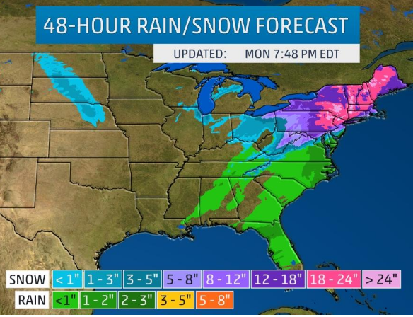
18" to 24" of snow predicted. I'm so excited! Hurrah!
Fuel for the generator, check. Food in the fridge, Check. Got a 9 HP 32" snowblower itchin' to be used, Check.
Bring it on!
18" to 24" of snow predicted. I'm so excited! Hurrah!
Fuel for the generator, check. Food in the fridge, Check. Got a 9 HP 32" snowblower itchin' to be used, Check.
Bring it on!
HilldaFlyer
Well-known member
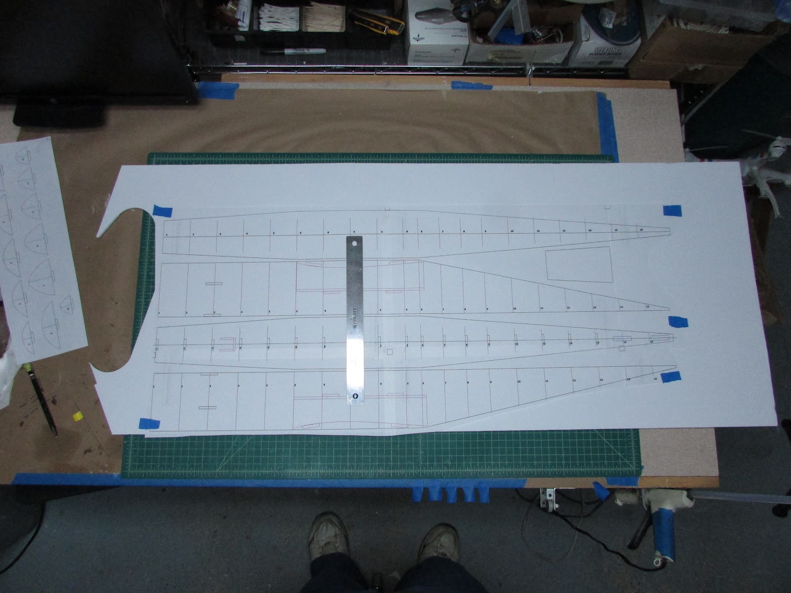
Printed out the plans, so I'm ready to tape and cut.
I'm going to try something new... so let me know if this works (more importantly, if it doesn't). I use google docs to track my progress making notes on what I do. Some times things get out of order, but nevertheless, it is more up-to-date than the thread. So, if you want to keep track in real time, or more real time, here is a link to my google doc.
Crosby CR4 HilldaFlyer Build 1/6th scale FT Style
Just north of you here in Maine and waiting for that 0530 call for a snow day at school. We're already extended a week in June but it is what it is. Ther's so much I hope to do... in between shoveling the driveway.So glad to hear it... I think I'll start tomorrow because I'm working from home..
ll
18" to 24" of snow predicted. I'm so excited! Hurrah!
Fuel for the generator, check. Food in the fridge, Check. Got a 9 HP 32" snowblower itchin' to be used, Check.
Bring it on!
PsyBorg
Wake up! Time to fly!
They already called my area a state emergency zone and have been listing closed businesses and schools since the announcement. On the bright side it will be a good few days to build providing people still have power. They still have 5000 people without power here from last weeks wind storms to get back up before all this hits.
Hope everyone stays safe and warm.
Hope everyone stays safe and warm.
HilldaFlyer
Well-known member
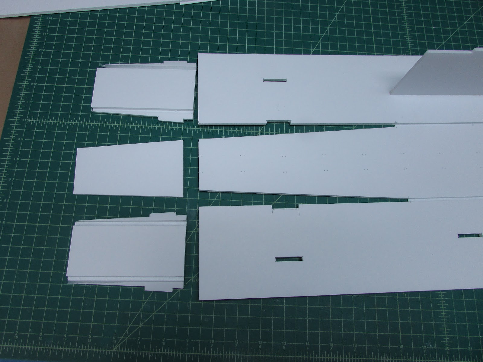
Trimmed the plans.
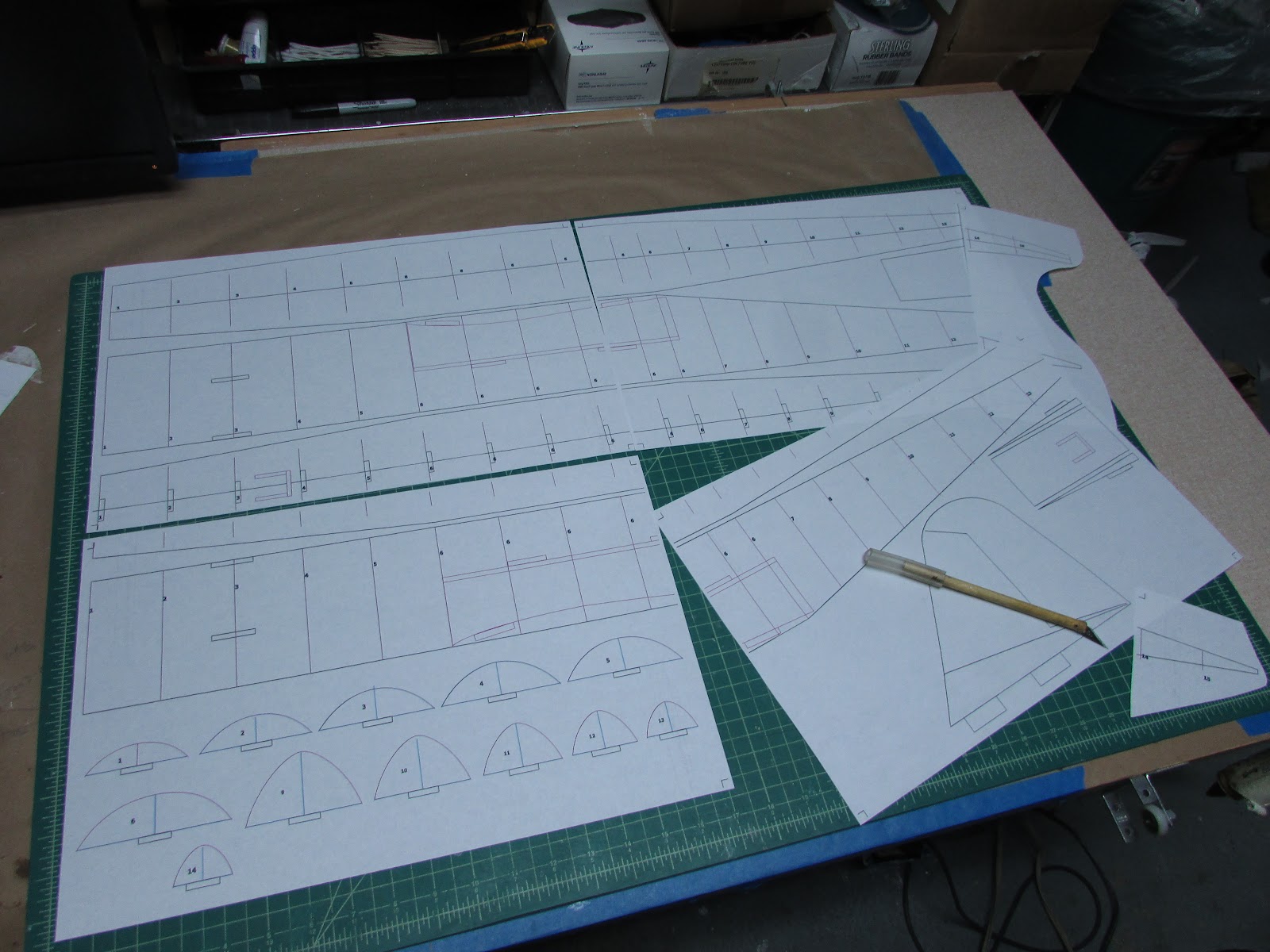
Cut out Wings,
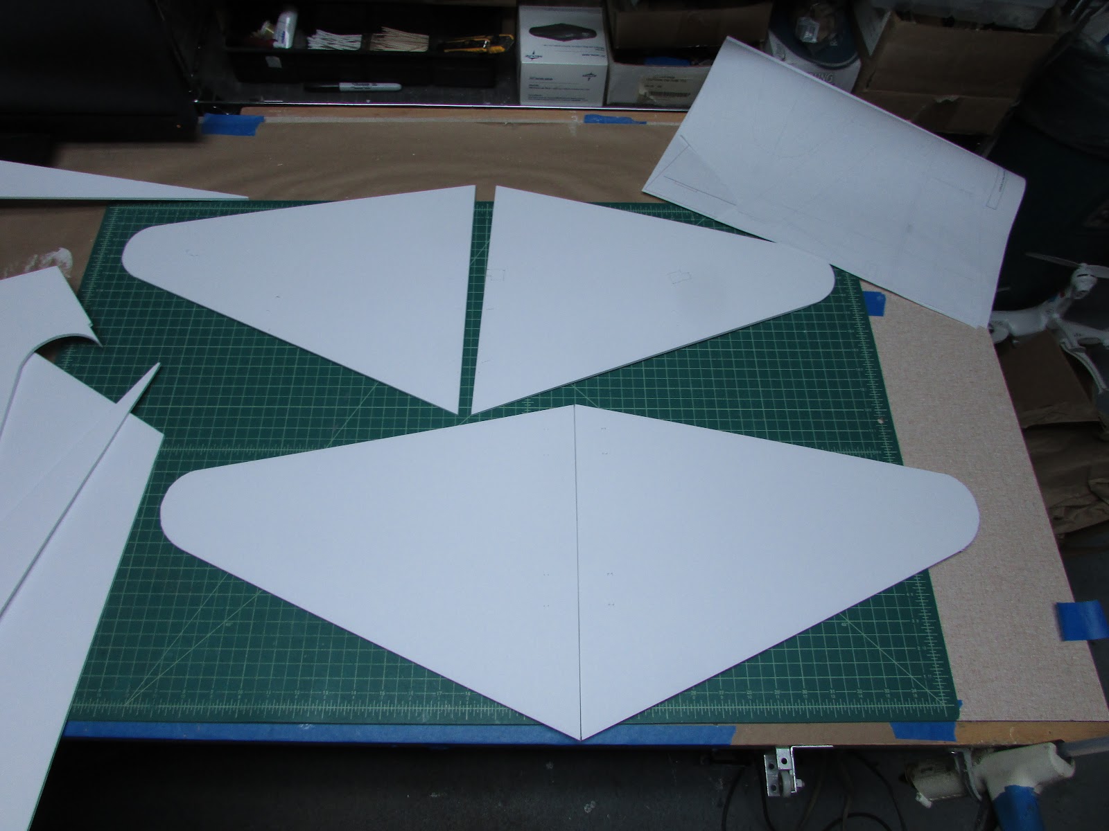
horizontal and vertical stabilizers,
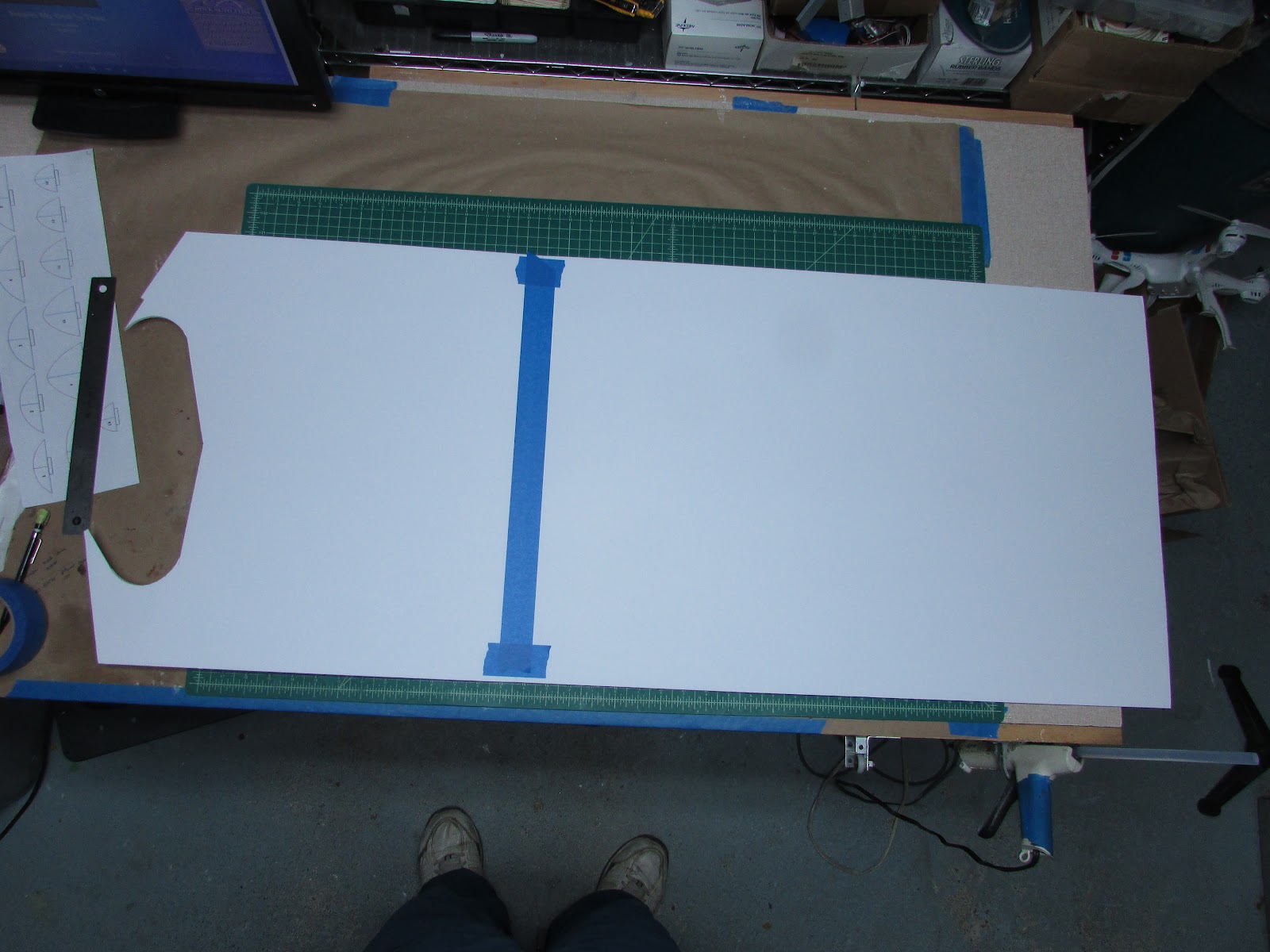
taped and glued two pieces of foam board and cut out the outline of the fuselage.
Crosby CR4 HilldaFlyer Build 1/6th scale FT Style
Cut out Wings,
horizontal and vertical stabilizers,
taped and glued two pieces of foam board and cut out the outline of the fuselage.
Crosby CR4 HilldaFlyer Build 1/6th scale FT Style
HilldaFlyer
Well-known member
Crosby CR4 1/6 scale FT Style
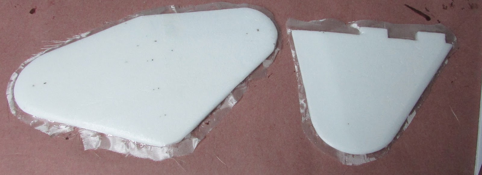
The tail pieces are going to be 2ply thick.
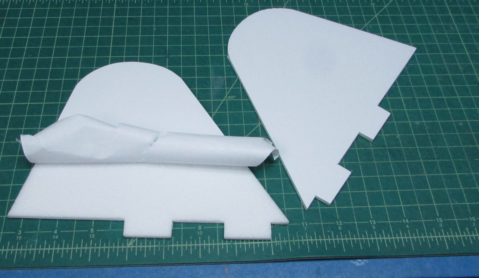
Peel the paper off of one side of both panels that will be glued together. Smear Gorilla glue on one side as thin as you can. I use a playing card to squeegee as much as possible. Lay the other piece on top of it and hold it in place with weight until it cures. Repeat with the horizontal stabilizer/elevator.
While that is curing, finish cutting out the fuselage Remove the masking tape using a hair dryer to warm it up a bit.
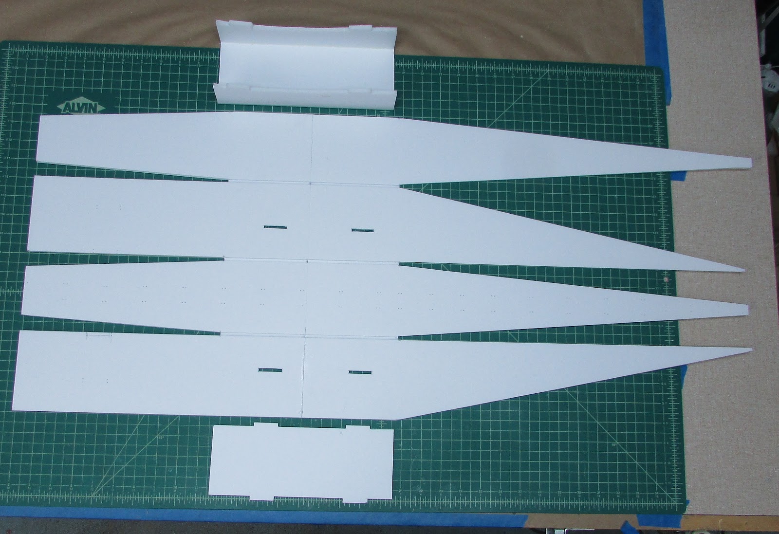
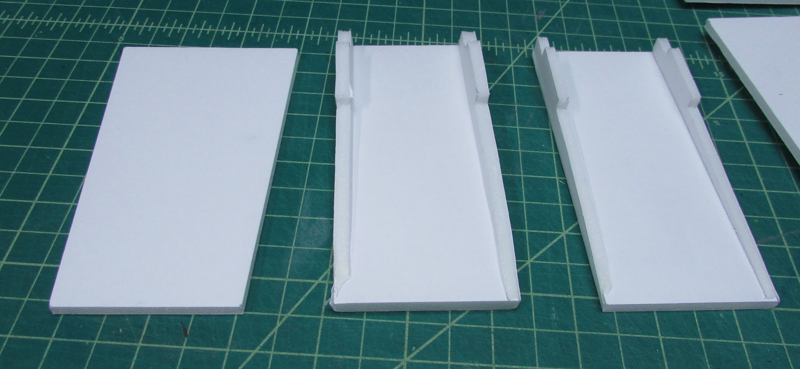
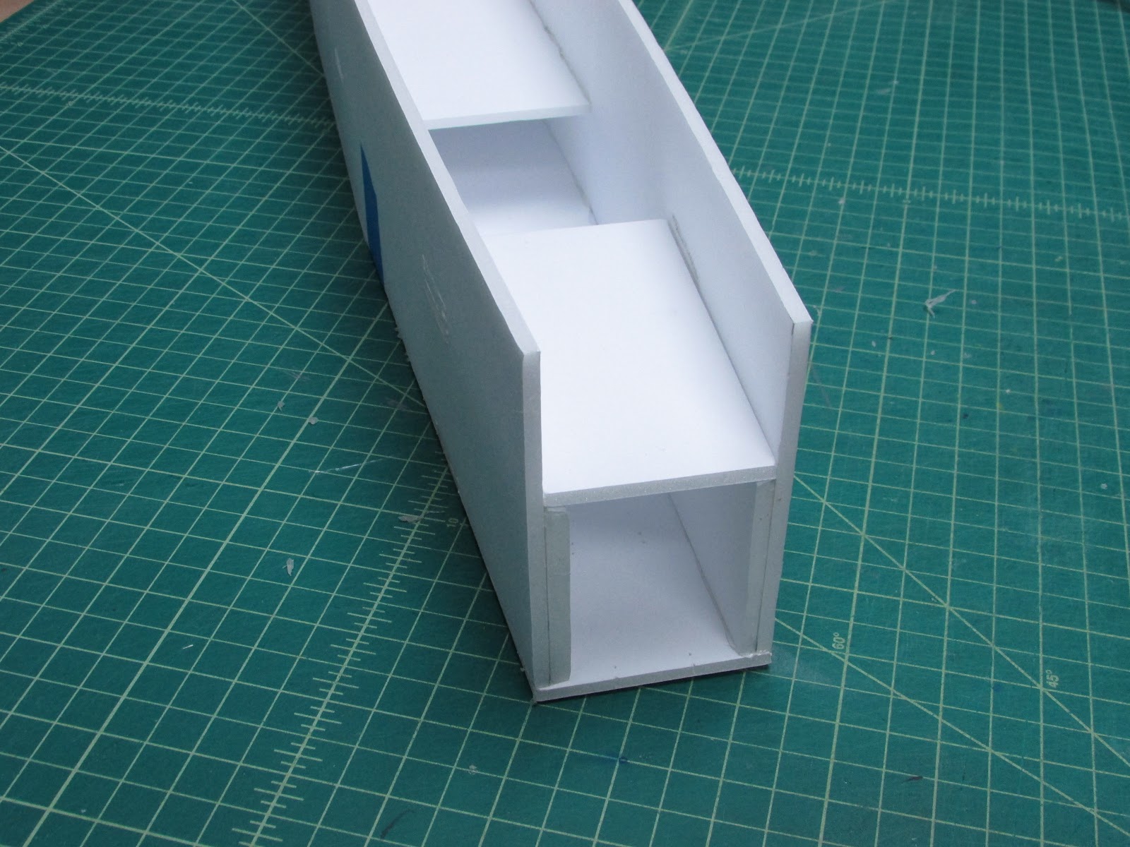
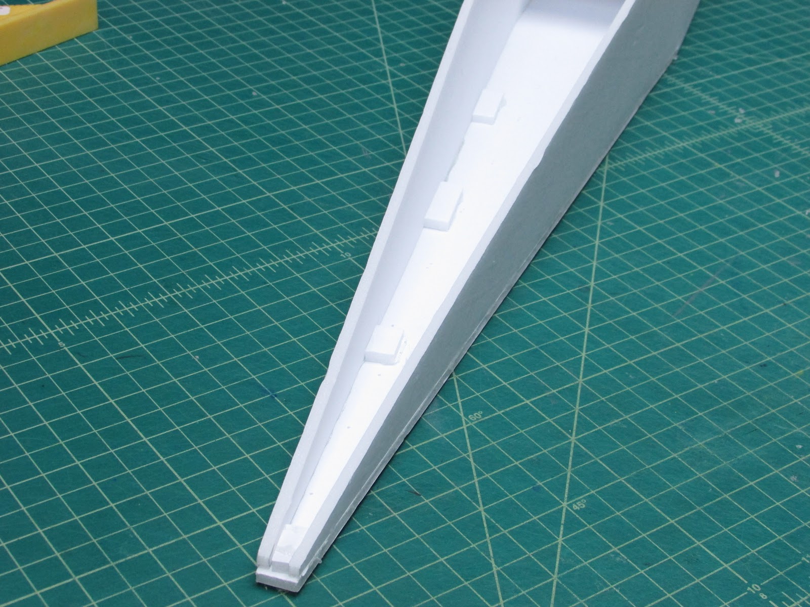
There are two several internal pieces that need to be in place when the fuselage is folded into shape. There is a wing support (top) and a fuselage spanner (bottom).
Punch the holes completely through for the former tabs and tail. The reason is to leave the foam in place until the fuselage is formed and then cut the holes.
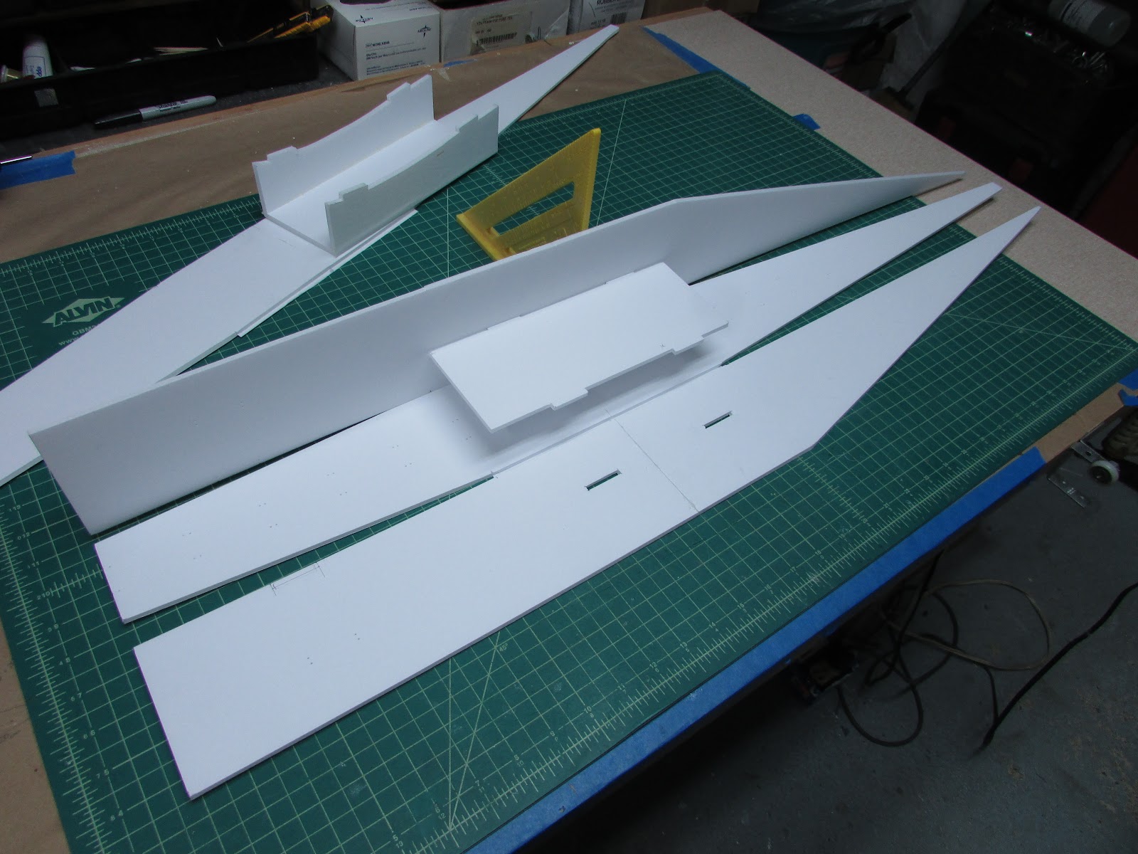
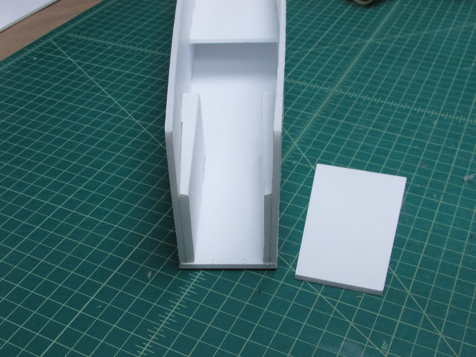
Glue the fuselage spanner to one side of the fuselage. It will look like this with one side stood up. Oh, I also cut the bottom fuselage panel from the other three since it will be cut into thirds and glued on last.
There are also motor mount guides. Two have notches and the other one will lay on top of the guides. Cut out the notches for the motor mount guides.
Glue the motor mount guides.
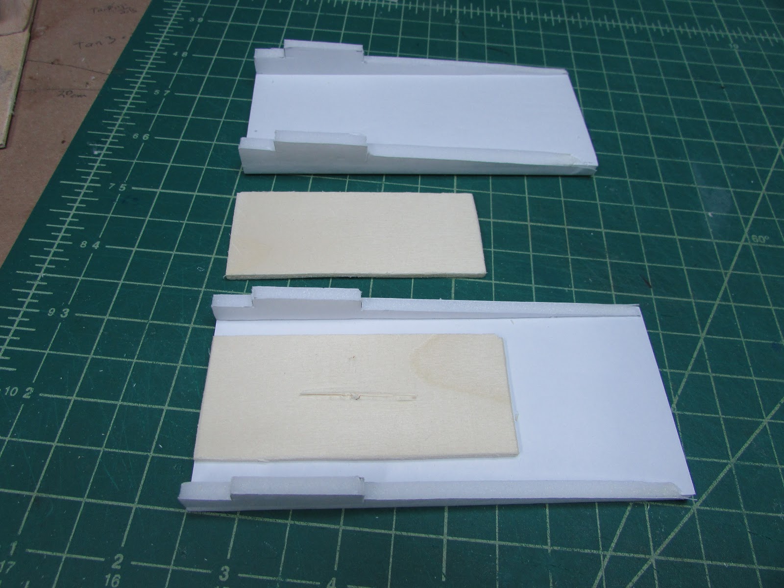
I will be using screws to hold the motor in the plane, so I line the motor mount guides with 3.5 cm x 8 cm x ⅛” plywood (this stuff came from the side of a tangerine box). Glue flush to the front of the motor mount slider. These can be attached to the front of the fuselage.
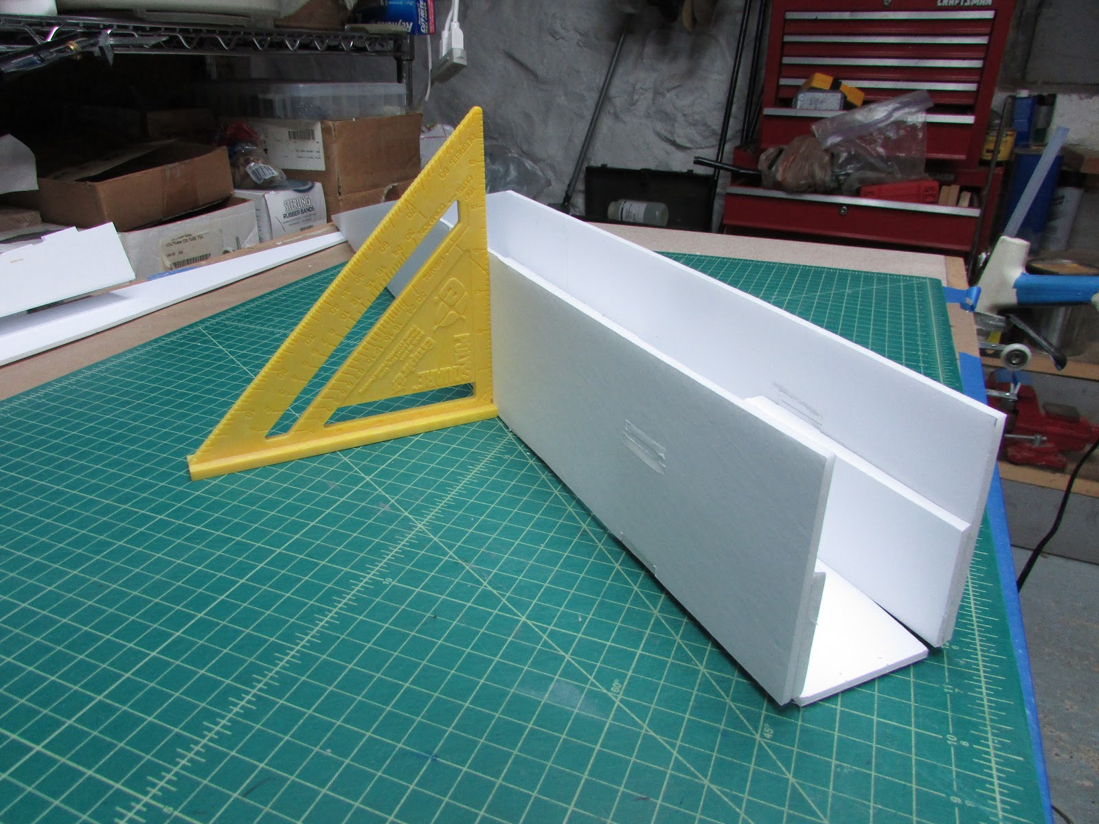
Glue one of the B folds that joins the side of the fuselage to the top. Use a right angle to get it square. Repeat for the other side.
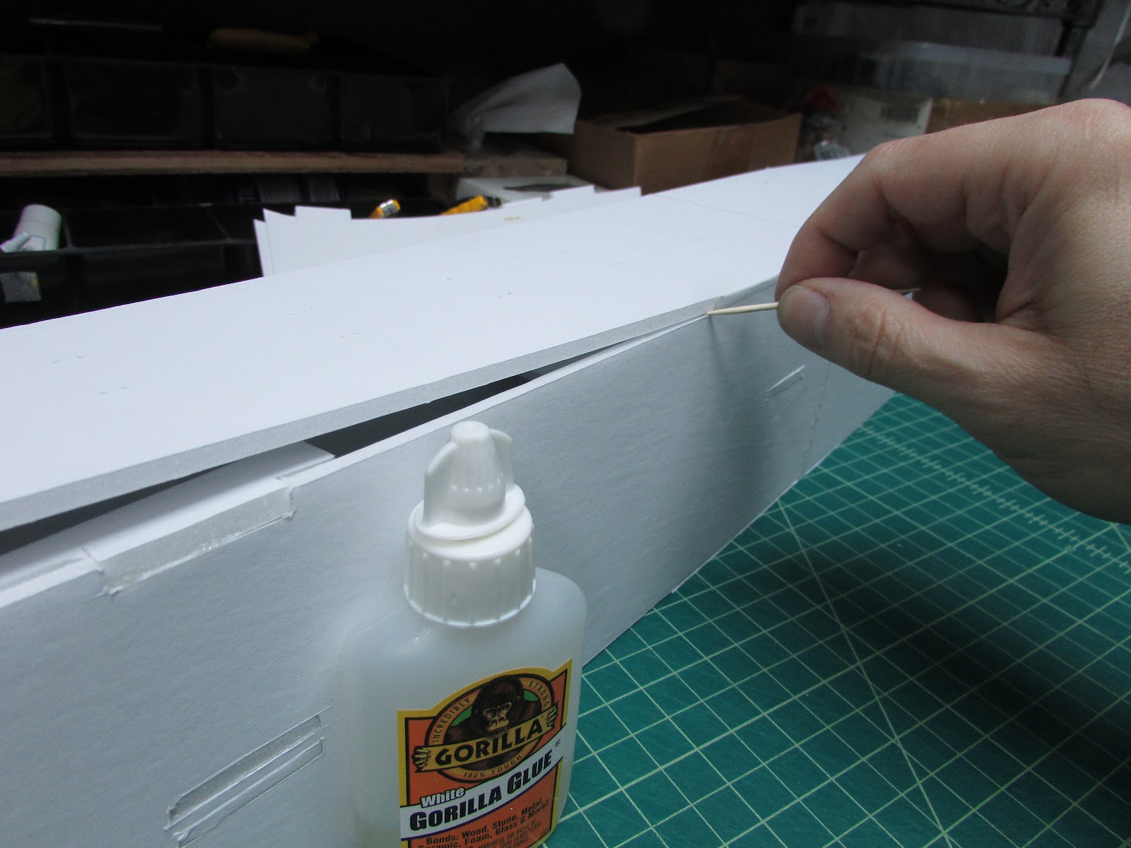
Glue the nose top to the fuselage sides. I smear a bit of Gorilla glue and smear it into place with a toothpick. For this build I will be using hot glue to expedite the build, however, If this were a final build, I’ll be using Gorilla glue for all the joints.
It looks like this when glued together.
The other motor mount guide will be glued into place across the other motor mount guides later. I want to make the motor mount before I glue this all together.
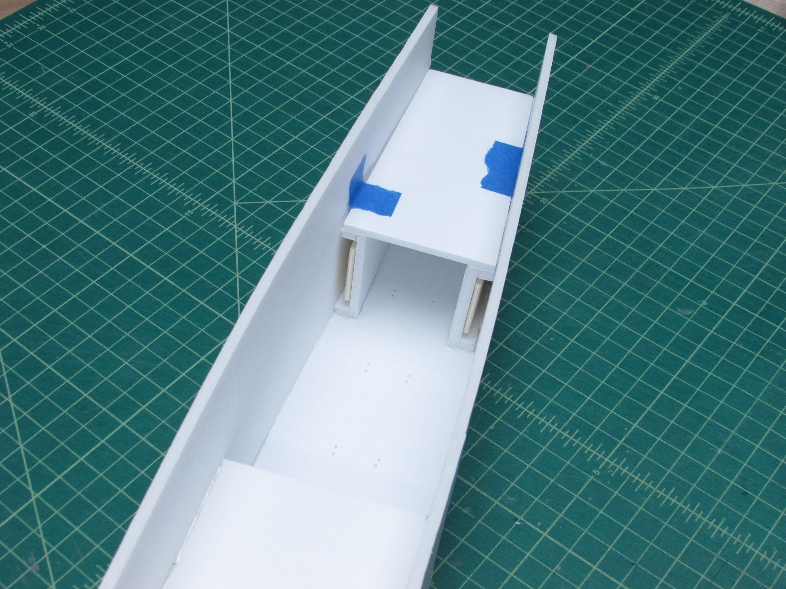
For now, I’ll just tape it in place.
To glue the tail together, I glue in little pieces of foam to butt the side piece against.
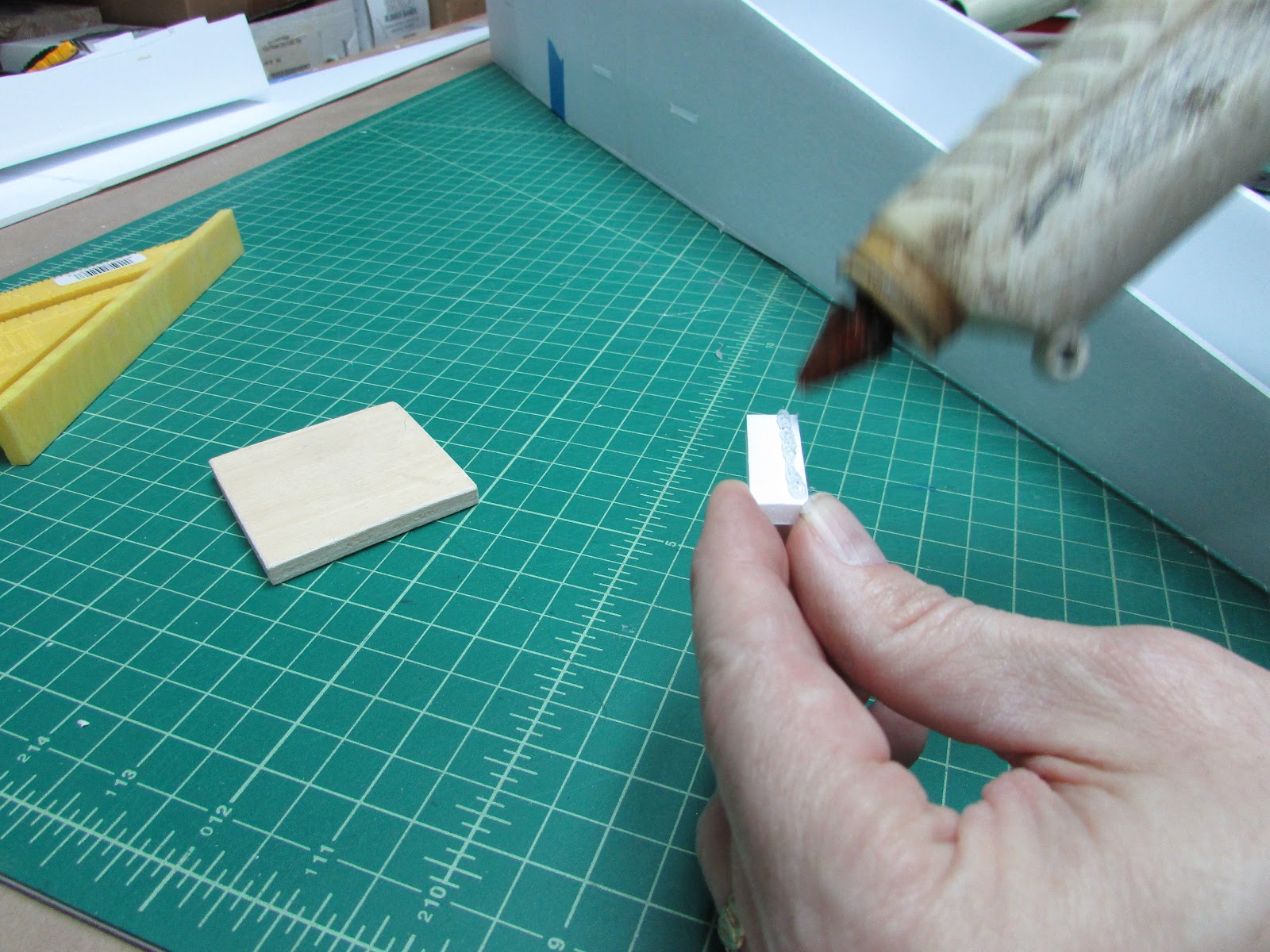
Take a small scrap of foam and add a little hot glue.
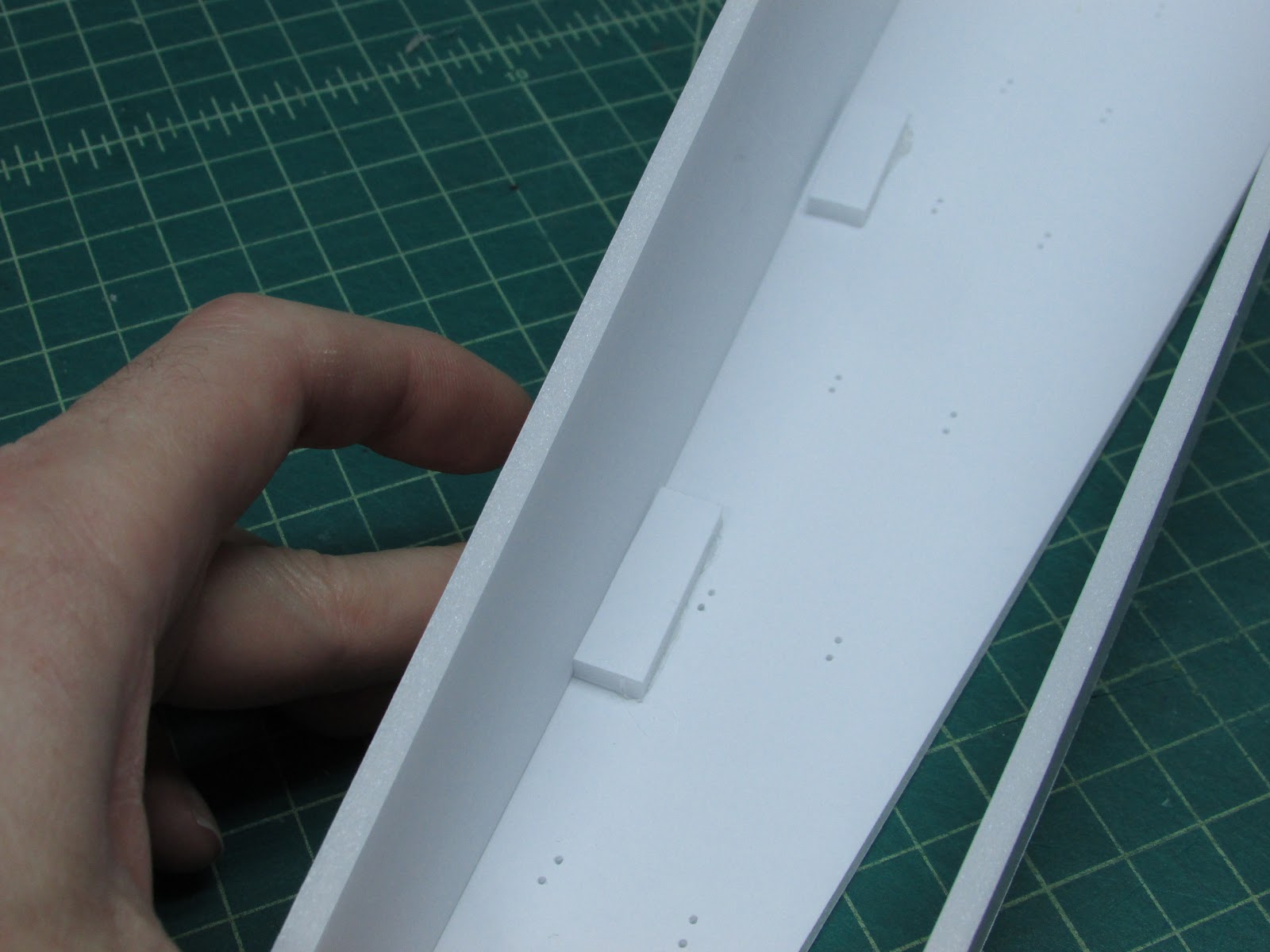
Hold the side piece in place with the proper flush side and glue the foam jam in place.
In all I made for jams per side.
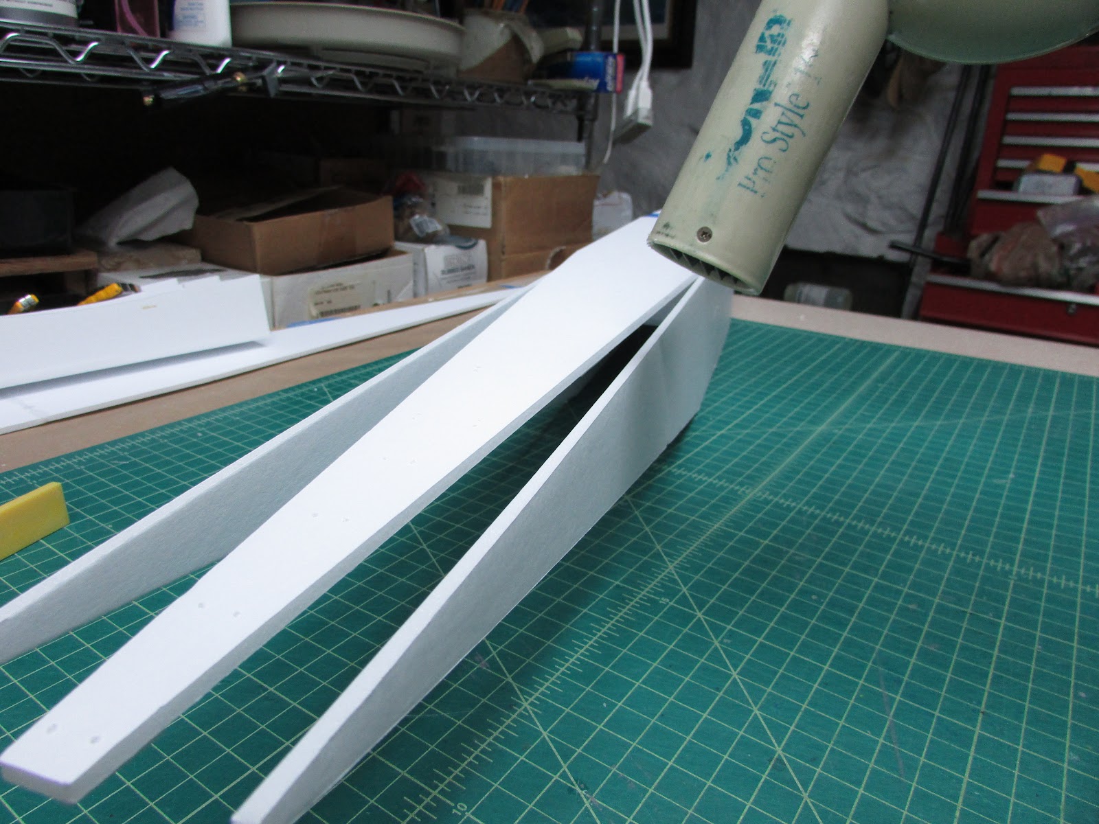
Because this is a long joint and it is 53 degrees F in my basement, I warm the joint with a hairdryer so the hot glue stays pliable for longer than 10 seconds.
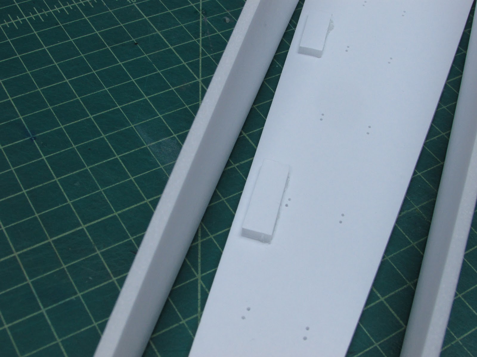
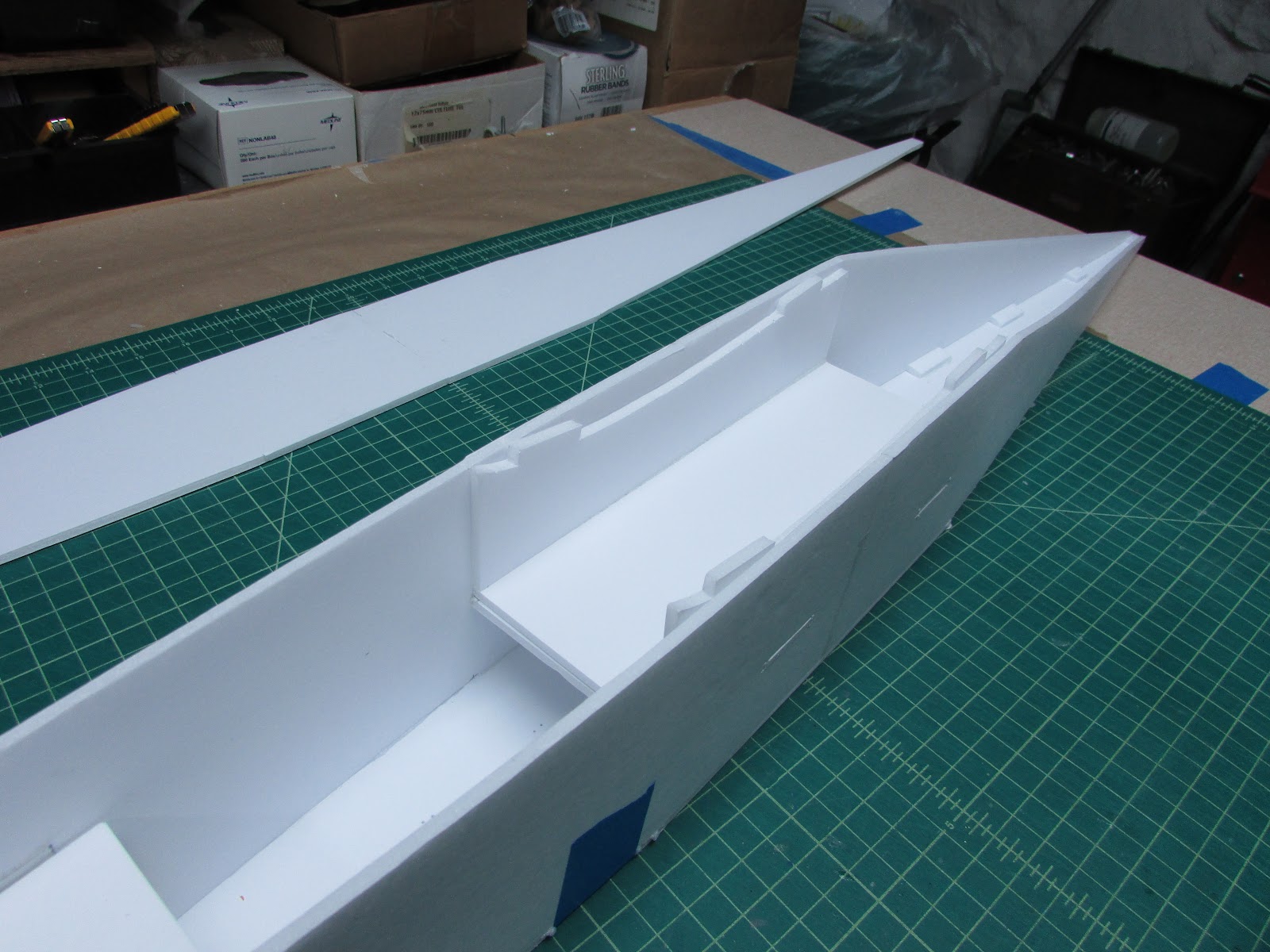
Glue the sides to the top fuselage piece.
It will look like this. The foam jams can be removed, but they’re not in the way so I’ll leave them for now.
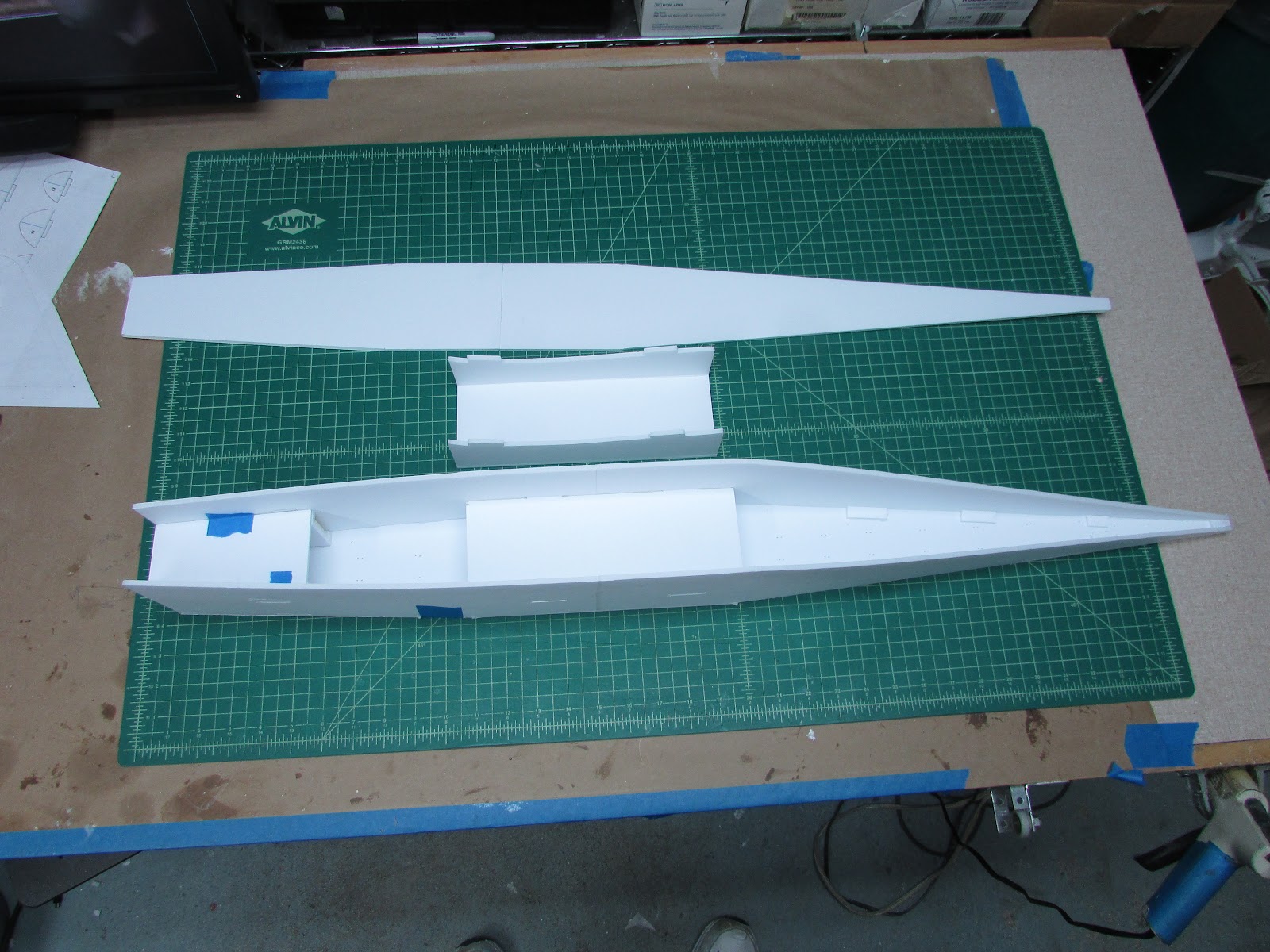
Here is the fuselage with the internal wing support from side to side, the wing joiner and the fuselage bottom panel.
When the wing alignment is attached to the wing it will slide inside the fuselage like this.
By now the Gorilla glue on the tail sections have cured.
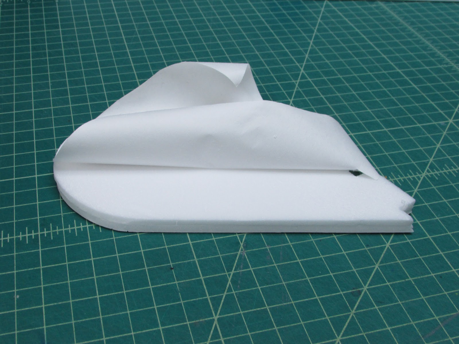
Peel the paper from the outside of the panels.
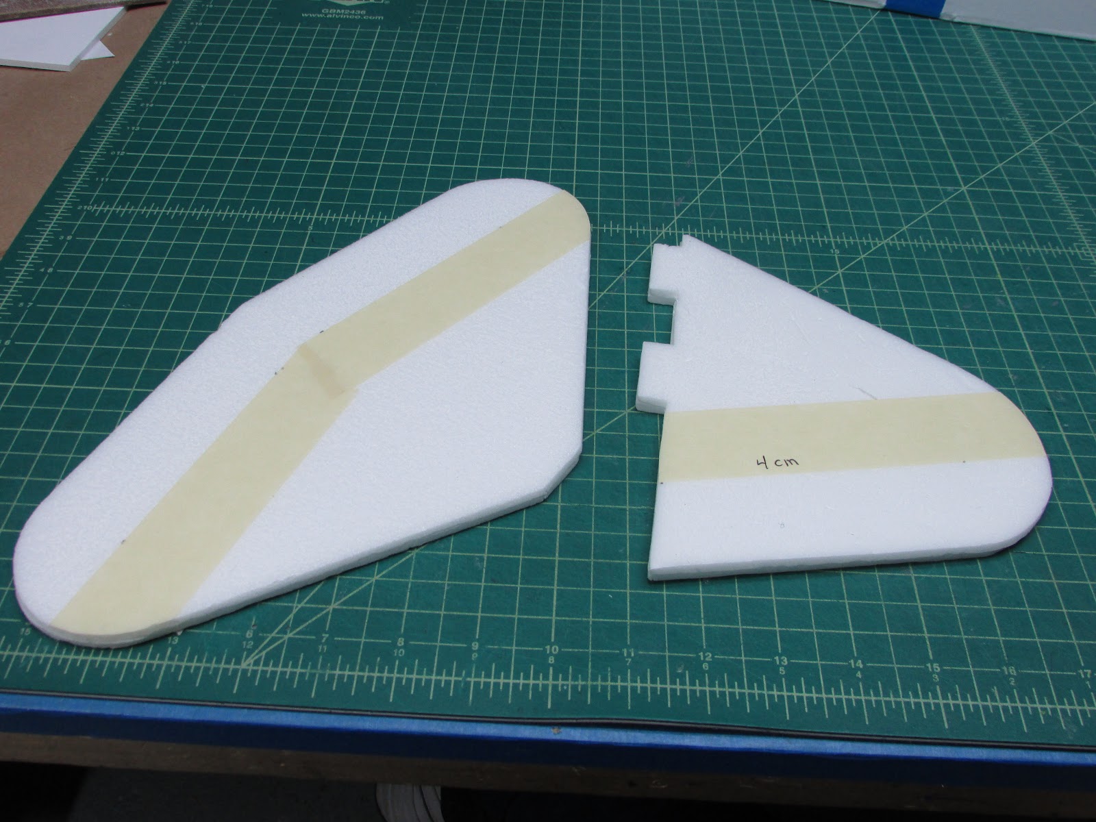
Mask of 4 cm from the trailing edge. This will protect the foam from sanding rash as the trailing edge is sanded to a point. Free hand sand the leading edge to a nice round shape.
Well, I’ve got to go, so I’ll pick this up later.
Crosby CR4 HilldaFlyer Build 1/6th scale FT Style
The tail pieces are going to be 2ply thick.
Peel the paper off of one side of both panels that will be glued together. Smear Gorilla glue on one side as thin as you can. I use a playing card to squeegee as much as possible. Lay the other piece on top of it and hold it in place with weight until it cures. Repeat with the horizontal stabilizer/elevator.
While that is curing, finish cutting out the fuselage Remove the masking tape using a hair dryer to warm it up a bit.
There are two several internal pieces that need to be in place when the fuselage is folded into shape. There is a wing support (top) and a fuselage spanner (bottom).
Punch the holes completely through for the former tabs and tail. The reason is to leave the foam in place until the fuselage is formed and then cut the holes.
Glue the fuselage spanner to one side of the fuselage. It will look like this with one side stood up. Oh, I also cut the bottom fuselage panel from the other three since it will be cut into thirds and glued on last.
There are also motor mount guides. Two have notches and the other one will lay on top of the guides. Cut out the notches for the motor mount guides.
Glue the motor mount guides.
I will be using screws to hold the motor in the plane, so I line the motor mount guides with 3.5 cm x 8 cm x ⅛” plywood (this stuff came from the side of a tangerine box). Glue flush to the front of the motor mount slider. These can be attached to the front of the fuselage.
Glue one of the B folds that joins the side of the fuselage to the top. Use a right angle to get it square. Repeat for the other side.
Glue the nose top to the fuselage sides. I smear a bit of Gorilla glue and smear it into place with a toothpick. For this build I will be using hot glue to expedite the build, however, If this were a final build, I’ll be using Gorilla glue for all the joints.
It looks like this when glued together.
The other motor mount guide will be glued into place across the other motor mount guides later. I want to make the motor mount before I glue this all together.
For now, I’ll just tape it in place.
To glue the tail together, I glue in little pieces of foam to butt the side piece against.
Take a small scrap of foam and add a little hot glue.
Hold the side piece in place with the proper flush side and glue the foam jam in place.
In all I made for jams per side.
Because this is a long joint and it is 53 degrees F in my basement, I warm the joint with a hairdryer so the hot glue stays pliable for longer than 10 seconds.
Glue the sides to the top fuselage piece.
It will look like this. The foam jams can be removed, but they’re not in the way so I’ll leave them for now.
Here is the fuselage with the internal wing support from side to side, the wing joiner and the fuselage bottom panel.
When the wing alignment is attached to the wing it will slide inside the fuselage like this.
By now the Gorilla glue on the tail sections have cured.
Peel the paper from the outside of the panels.
Mask of 4 cm from the trailing edge. This will protect the foam from sanding rash as the trailing edge is sanded to a point. Free hand sand the leading edge to a nice round shape.
Well, I’ve got to go, so I’ll pick this up later.
Crosby CR4 HilldaFlyer Build 1/6th scale FT Style
Last edited:
HilldaFlyer
Well-known member
Thanks - I like to warm up all the wood I use, like plywood etc because it tends to set up real quick. People living in warmer climates don't have to worry about this. Also... if you want your Gorilla glue to really puff up, hit it with some heat. I think you can get 10x expansion.I hadn't thought of heating up the foam to extend the hot glue working time - great idea!
HilldaFlyer
Well-known member
I made a LOT of progress this week. I'm going to deliver the progress in several installments. I generally spend some of my evening building and not organizing my documentation. So... here goes.
HilldaFlyer
Well-known member
Crosby CR4 1/6 scale FT Style - Tail
This block will cover finishing the tail.
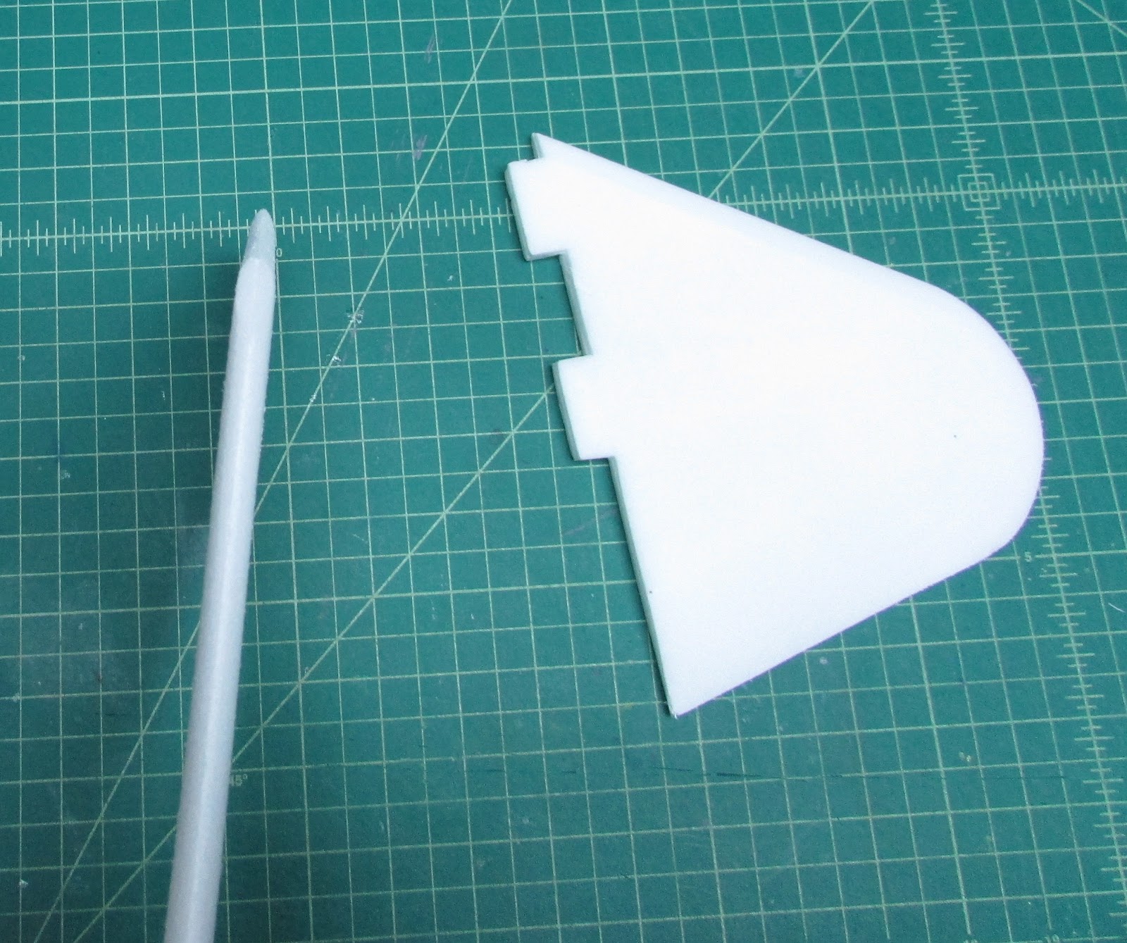
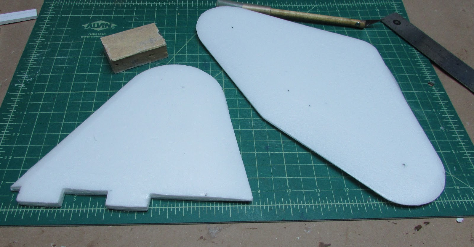
The leading edges are rounded.
The tailing edges are tapered to a point from 4 mm from the trailing edge. I usually make the trailing edge about 1 mm thick.
Time for fiberglass skin.
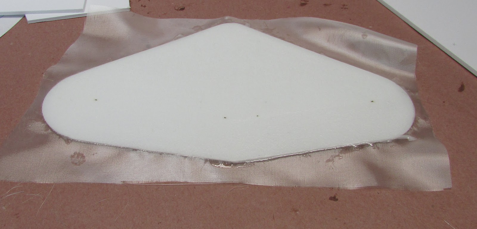
Overlay the foam with 0.73 oz/yd fiberglass and wet out with epoxy resin. The cloth is light enough that it lays down nicely on the leading and trailing edges.
After it cures, repeat the process on the other side.
Trim and sand the edges.
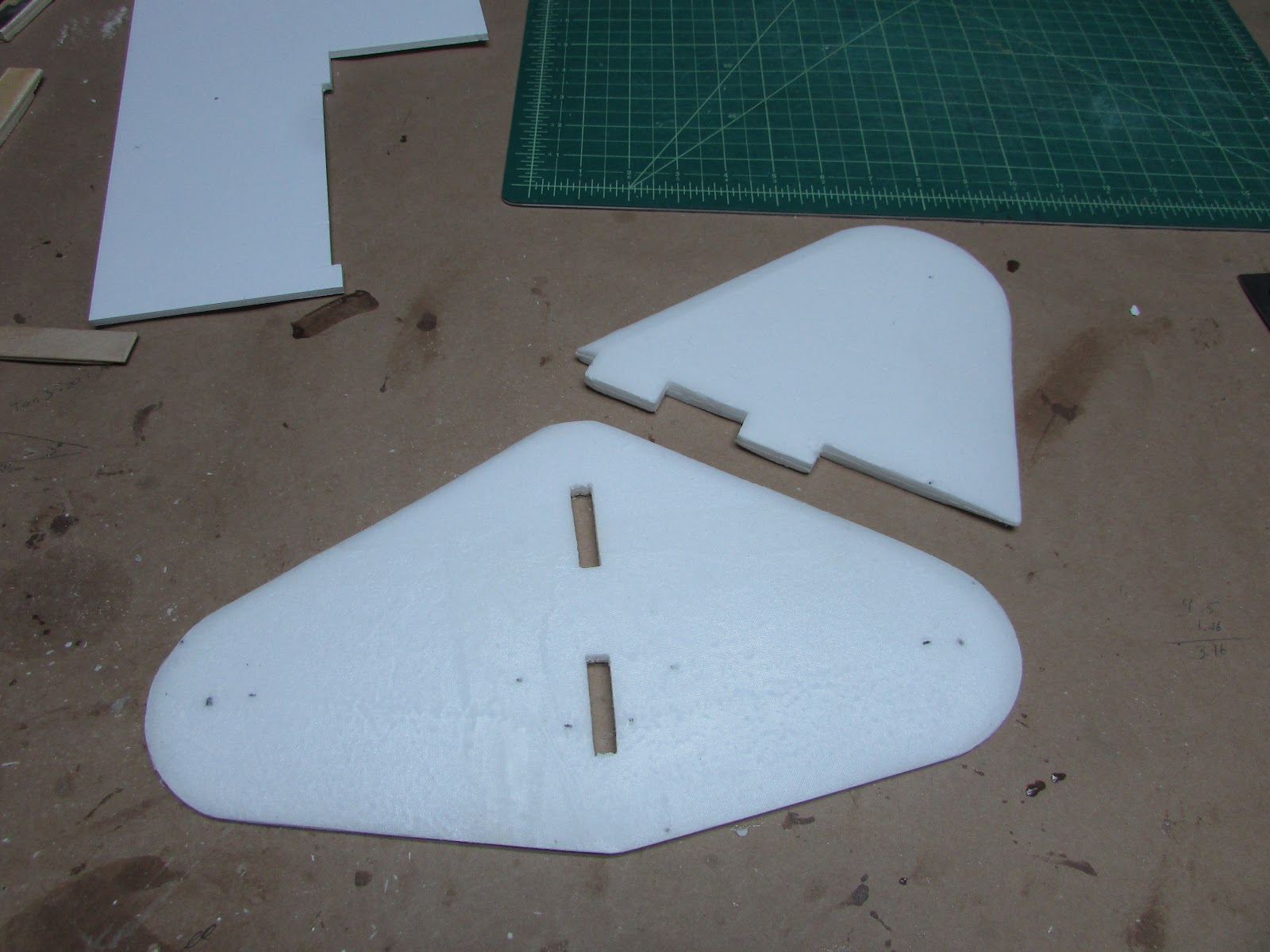
Cut the tab holes into the horizontal stabilizer.
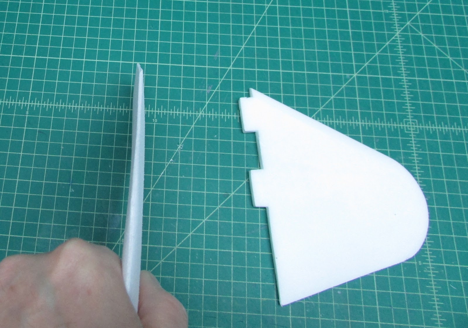
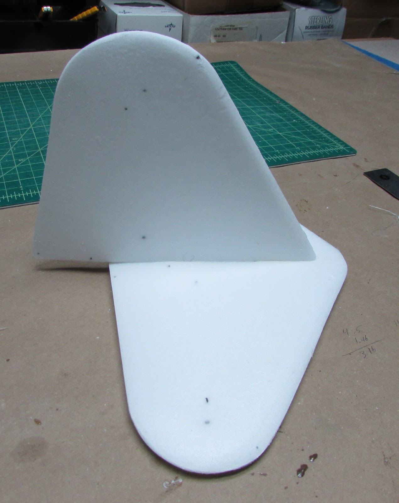 Test fit the vertical stabilizer into the horizontal stabilizer.
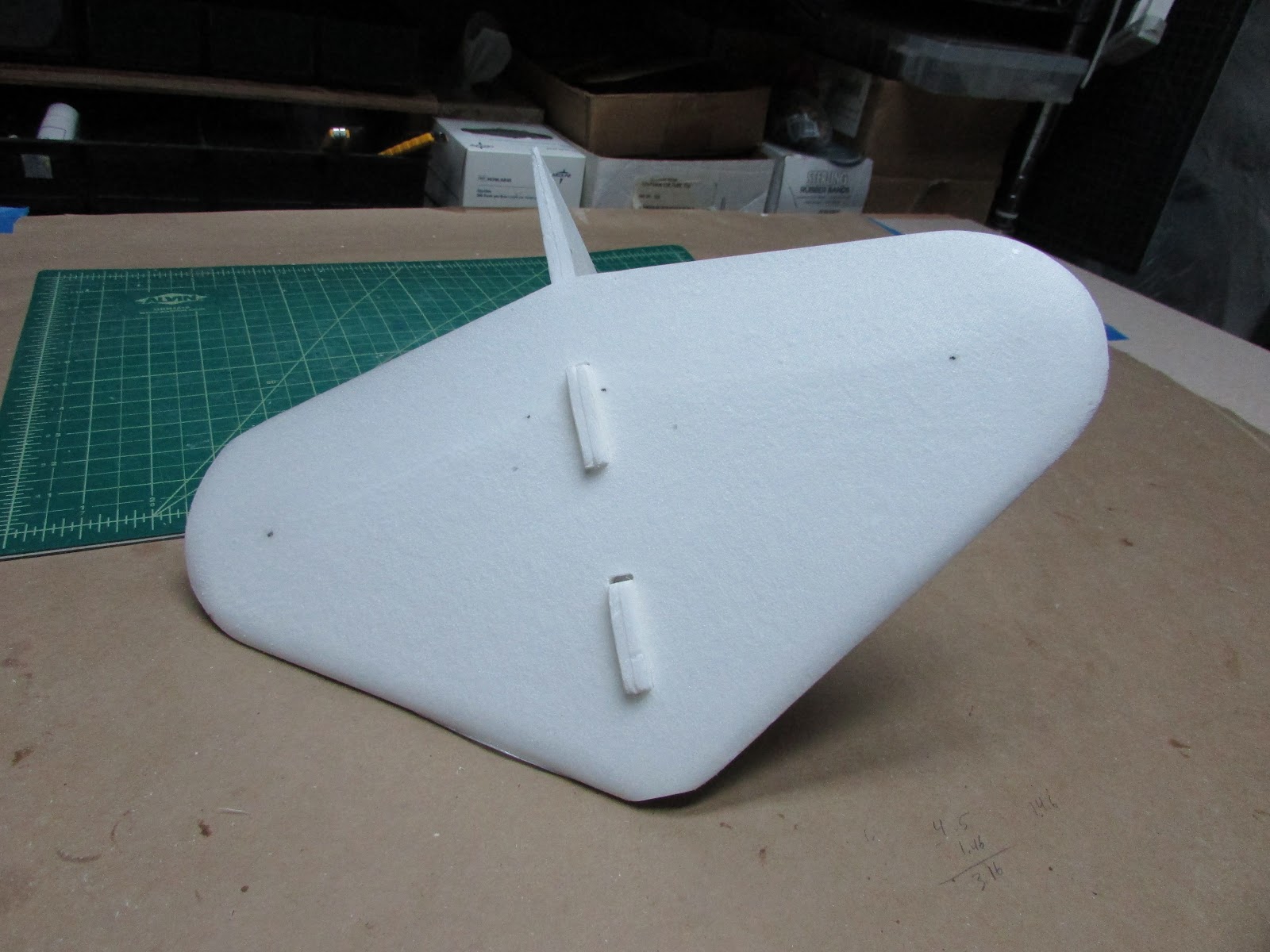
The tabs should extend underneath for mounting to the fuselage. Note that the tab hole in the front is slightly larger than it needed to be. This is where the servo wires will go.
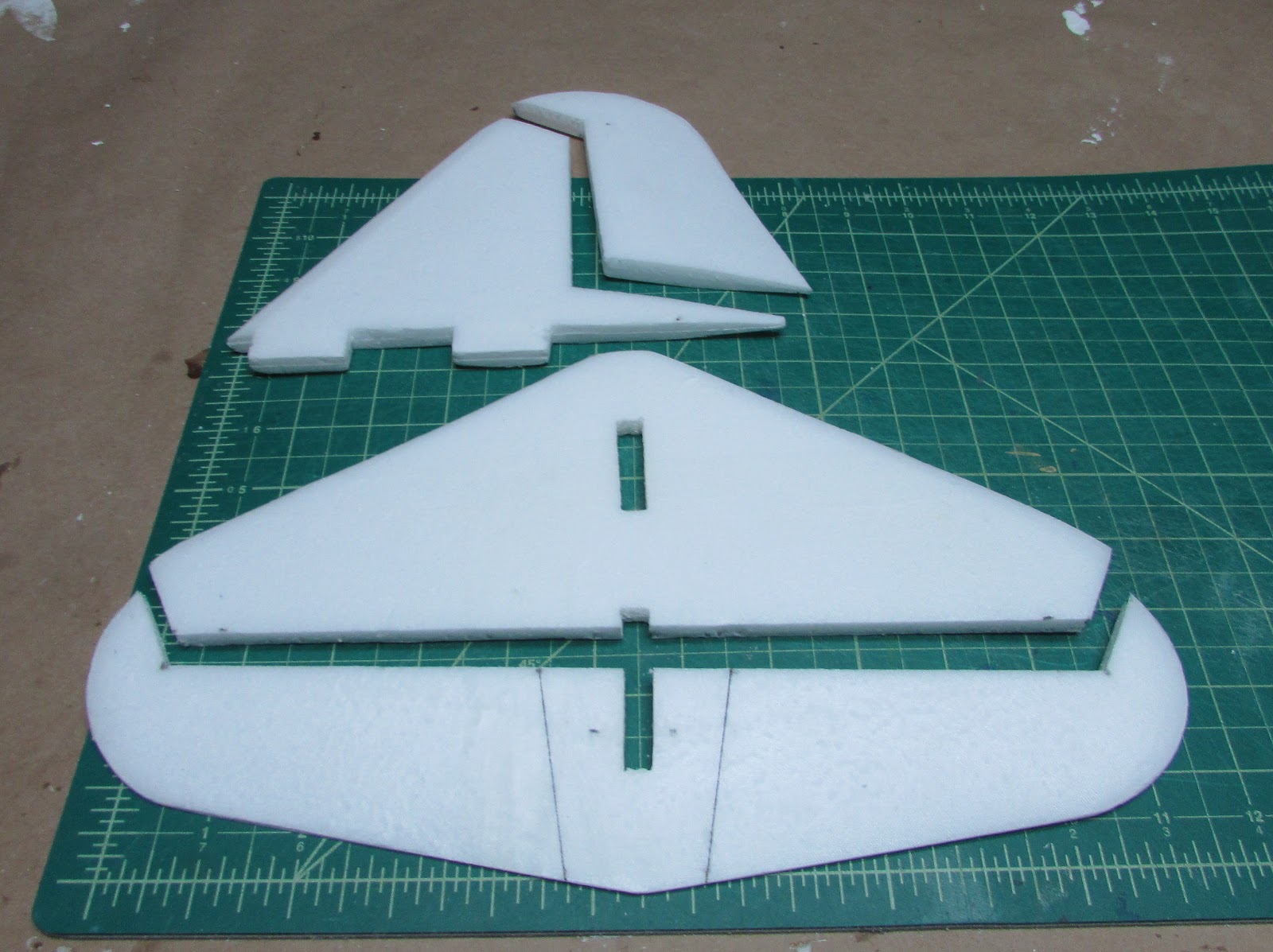
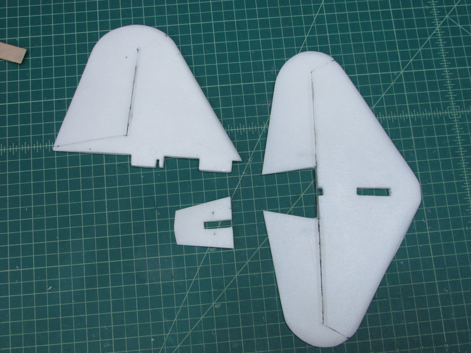
Cut the rudder and elevator control surfaces. Note that I drew lines on the elevator where they will be cut to separate the elevators, however, I left them together in order to put on a joiner. The middle piece will be cut out and glue on separately later.
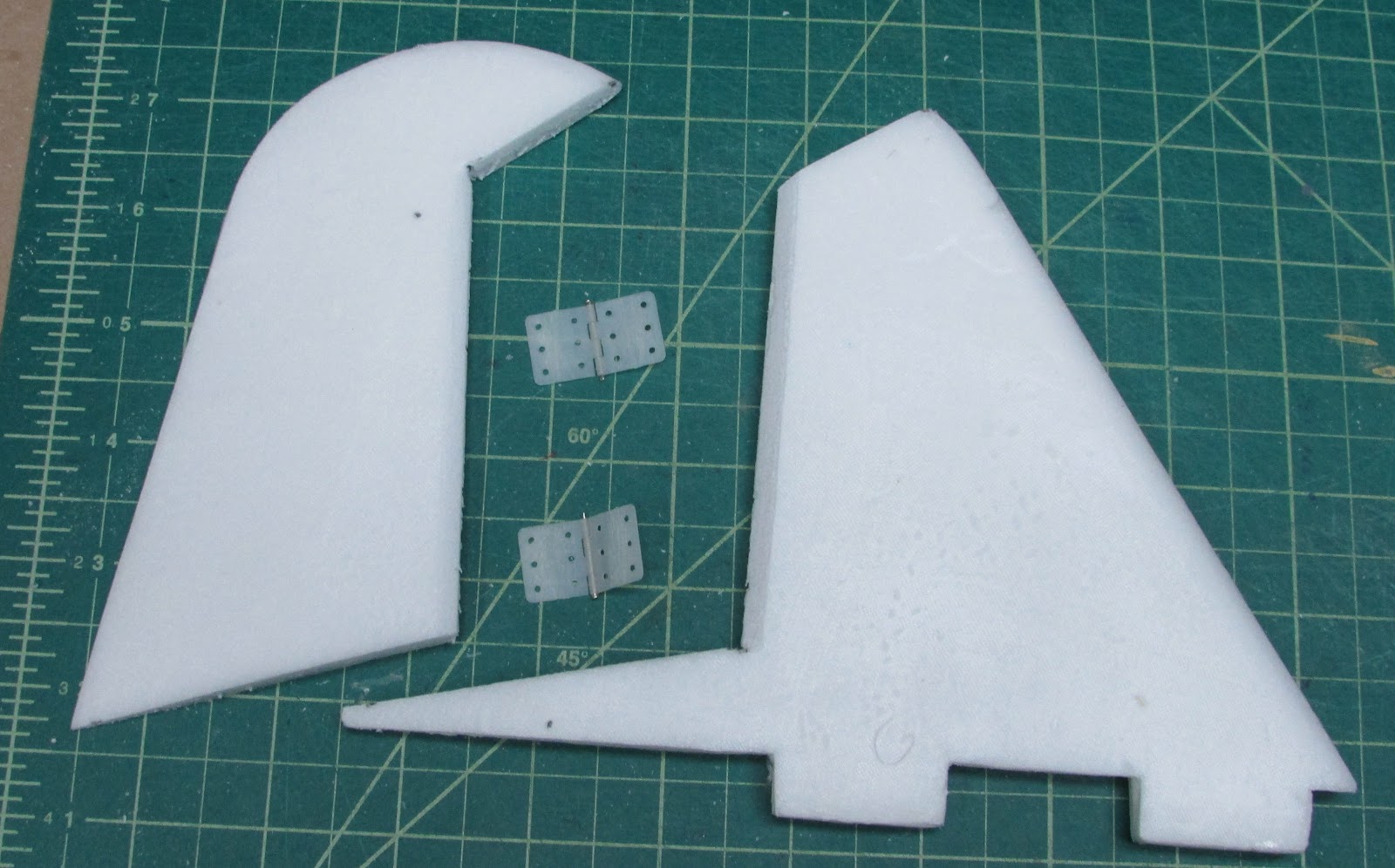
Bevel the joint edges of the rudder and cut slots for hinges. This is the first build that I have used pin hinges. I have to say I really like them, especially on control surfaces that are two foam sheets thick. Usually I use polyester cloth and epoxy.
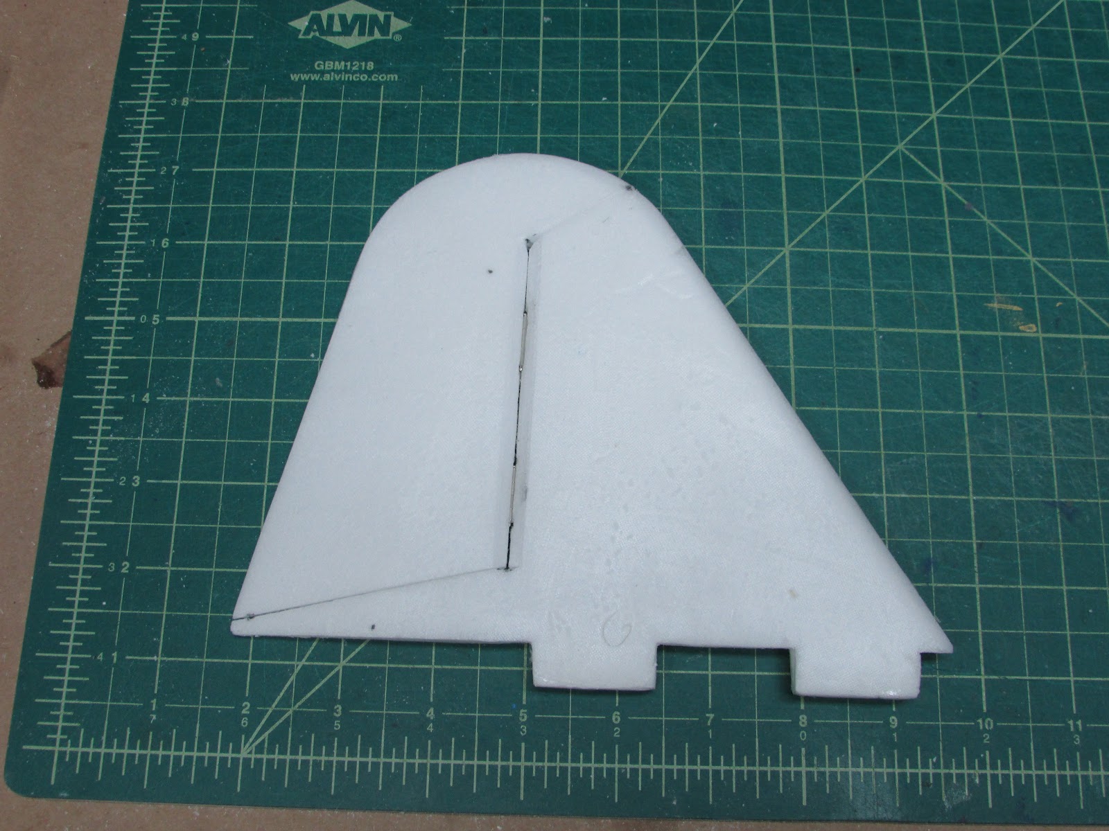
Glue the rudder to the vertical stabilizer. I used epoxy.
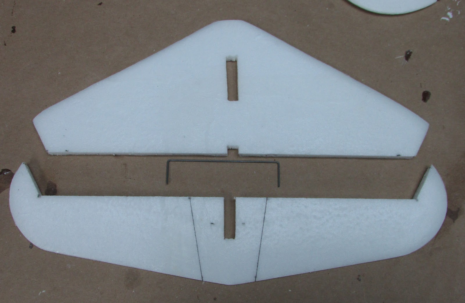
Here is the plan for the elevators. I used a bent piece of music wire and poked it into the elevators. Then I glued it into place without gluing the music wire to the middle section between the lines.
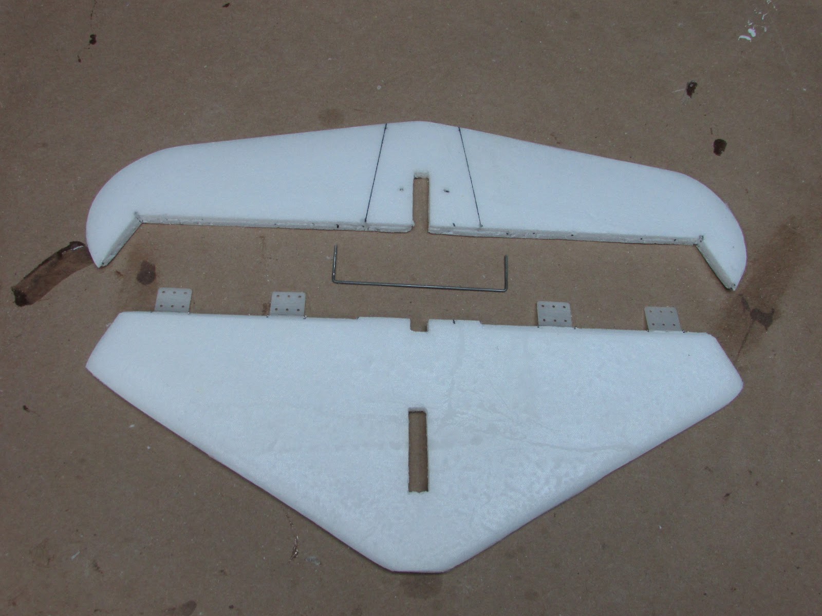
The hinge surfaces were beveled hinges glue into place.
Jointing the elevators to the horizontal stabilizer.
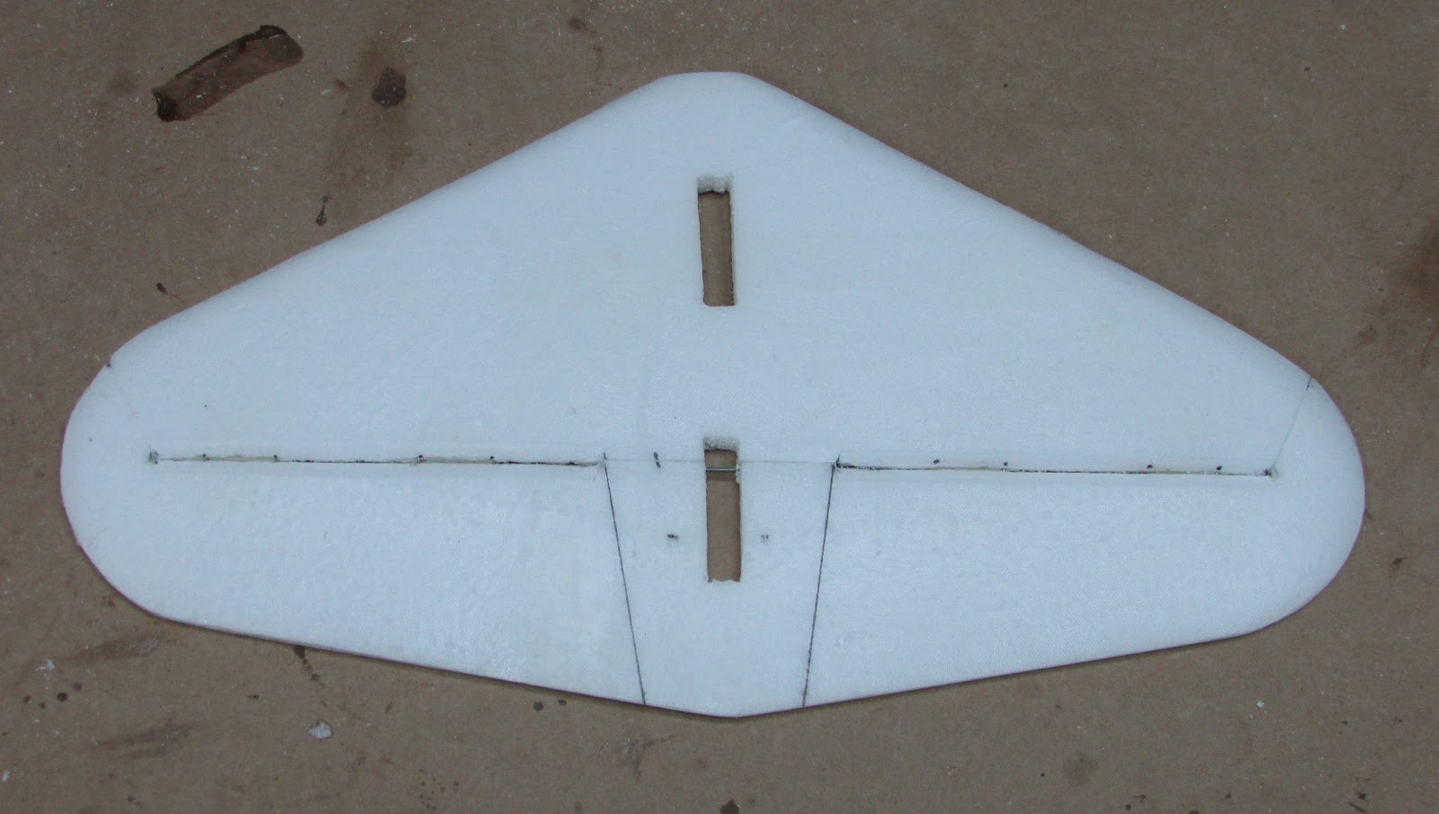
After the hinge glue is cured, the middle section can be cut out and a notch cut into the tab of the vertical stabilizer to straddle the music wire the goes between the elevators.
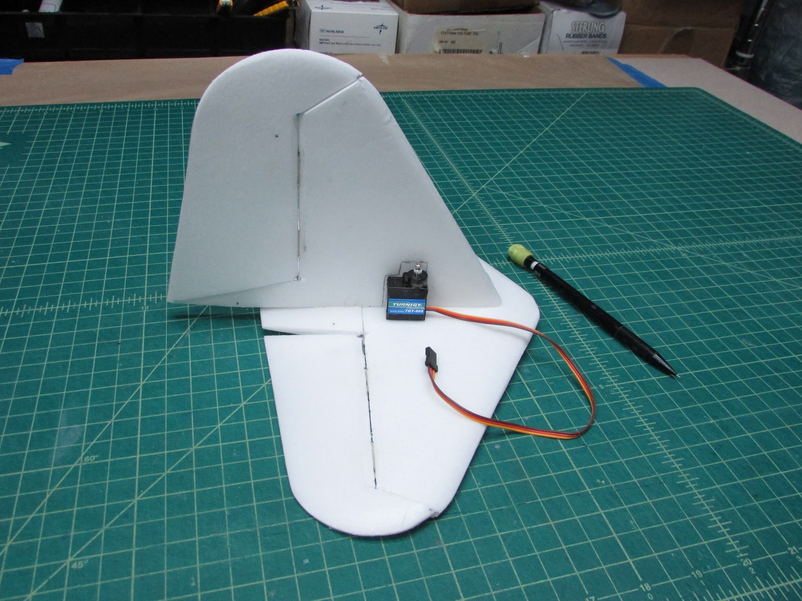
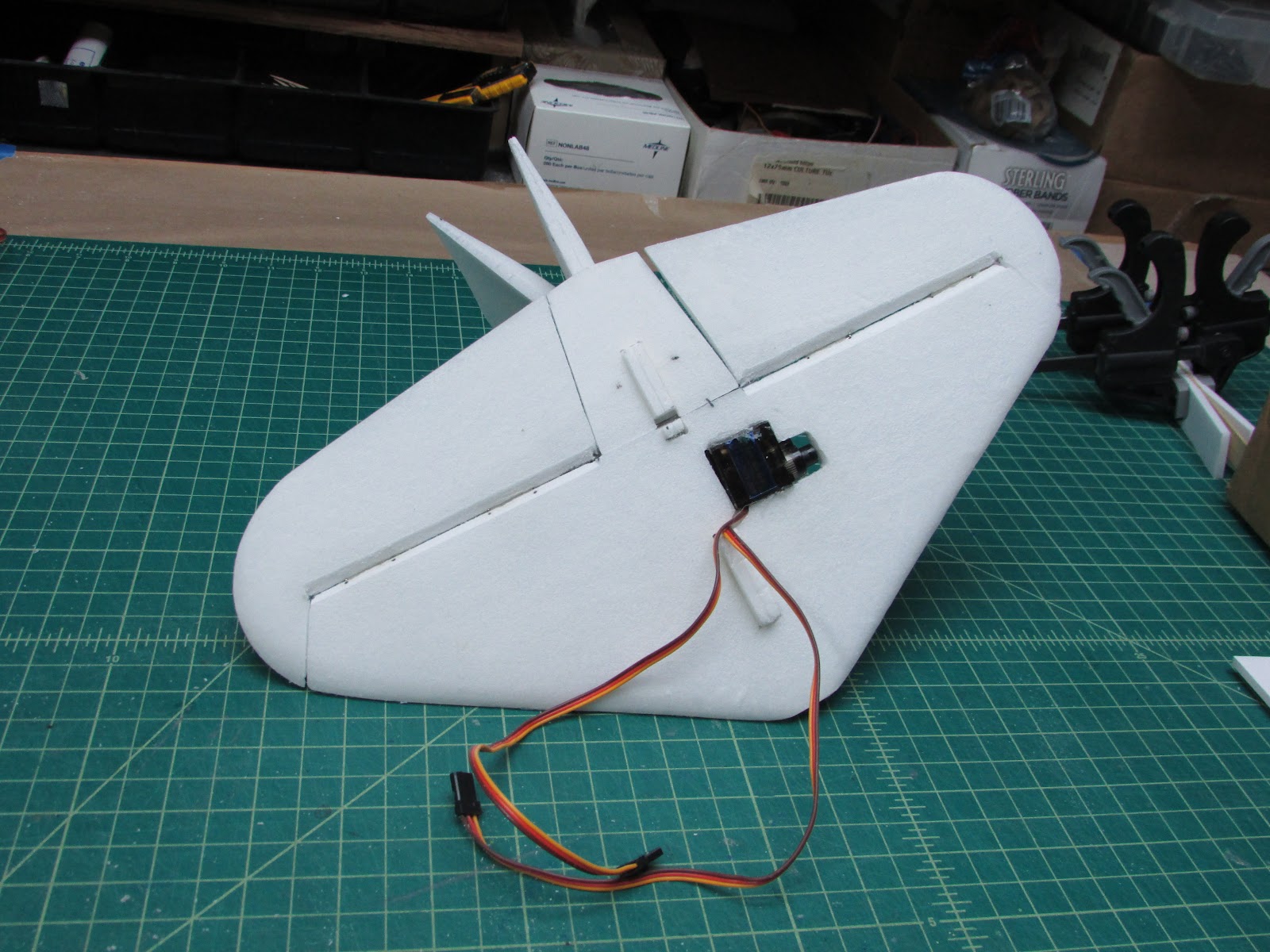
Perfect fit. I want to hide the rudder servo as much as possible so embedding it into the vertical stabilizer seemed like a great option.
Draw a line where you want it to go. I placed it just behind the tab so that the wire could feed down to the fuselage through the tab hole.
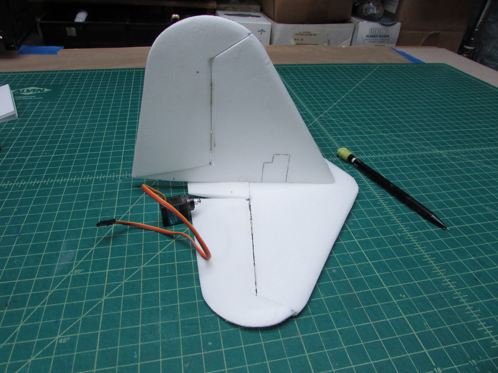
The same process for mounting the elevator servo in the horizontal stabilizer can be done. Note that the servo leads go into the vertical stabilizer’s tab hole, where it will go down into the fuselage.
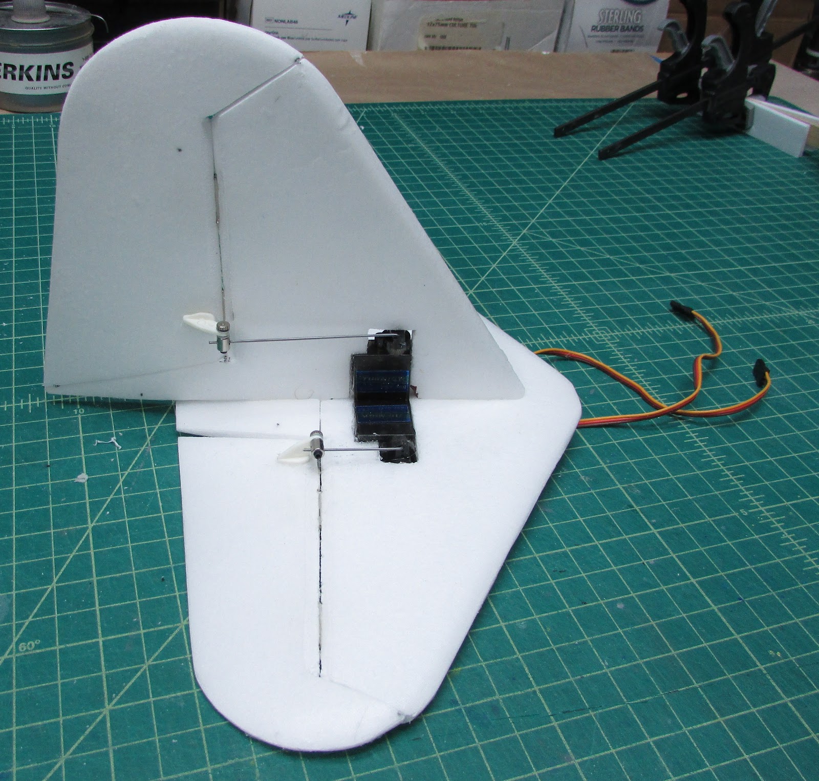
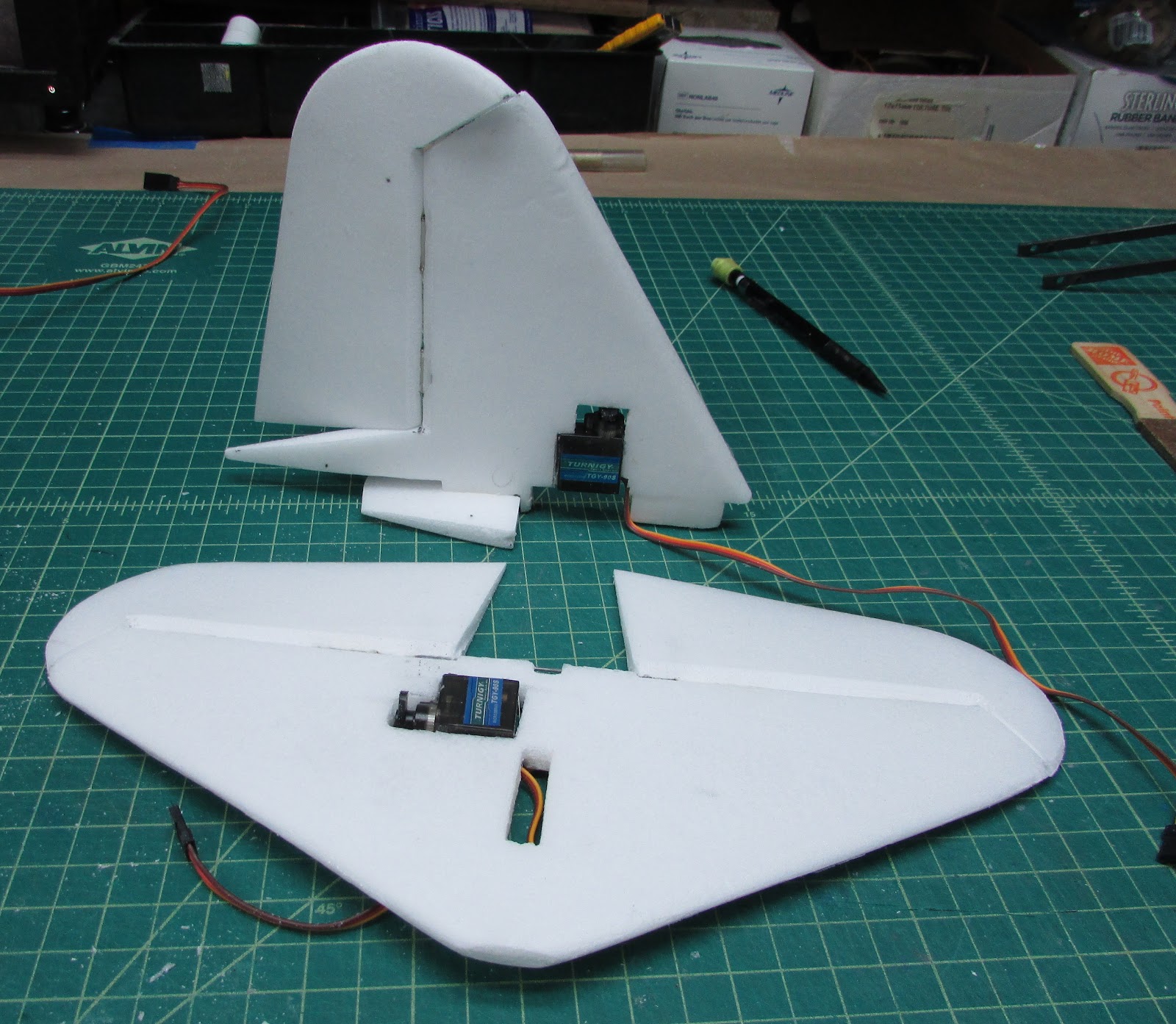
Glue them together and this is what it looks like from the right.
From the bottom.
Follow the progress Here:
Crosby CR4 HilldaFlyer Build 1/6th scale FT Style
This block will cover finishing the tail.
The leading edges are rounded.
The tailing edges are tapered to a point from 4 mm from the trailing edge. I usually make the trailing edge about 1 mm thick.
Time for fiberglass skin.
Overlay the foam with 0.73 oz/yd fiberglass and wet out with epoxy resin. The cloth is light enough that it lays down nicely on the leading and trailing edges.
After it cures, repeat the process on the other side.
Trim and sand the edges.
Cut the tab holes into the horizontal stabilizer.
The tabs should extend underneath for mounting to the fuselage. Note that the tab hole in the front is slightly larger than it needed to be. This is where the servo wires will go.
Cut the rudder and elevator control surfaces. Note that I drew lines on the elevator where they will be cut to separate the elevators, however, I left them together in order to put on a joiner. The middle piece will be cut out and glue on separately later.
Bevel the joint edges of the rudder and cut slots for hinges. This is the first build that I have used pin hinges. I have to say I really like them, especially on control surfaces that are two foam sheets thick. Usually I use polyester cloth and epoxy.
Glue the rudder to the vertical stabilizer. I used epoxy.
Here is the plan for the elevators. I used a bent piece of music wire and poked it into the elevators. Then I glued it into place without gluing the music wire to the middle section between the lines.
The hinge surfaces were beveled hinges glue into place.
Jointing the elevators to the horizontal stabilizer.
After the hinge glue is cured, the middle section can be cut out and a notch cut into the tab of the vertical stabilizer to straddle the music wire the goes between the elevators.
Perfect fit. I want to hide the rudder servo as much as possible so embedding it into the vertical stabilizer seemed like a great option.
Draw a line where you want it to go. I placed it just behind the tab so that the wire could feed down to the fuselage through the tab hole.
The same process for mounting the elevator servo in the horizontal stabilizer can be done. Note that the servo leads go into the vertical stabilizer’s tab hole, where it will go down into the fuselage.
Glue them together and this is what it looks like from the right.
From the bottom.
Follow the progress Here:
Crosby CR4 HilldaFlyer Build 1/6th scale FT Style
HilldaFlyer
Well-known member
Crosby CR4 1/6 scale FT Style - the Wing
The wings have been setting on the shelf for a while now. First I’ll show you how to make a spar, then the wing will go together. Not just any spar… a “I” beam carbon fiber spar.
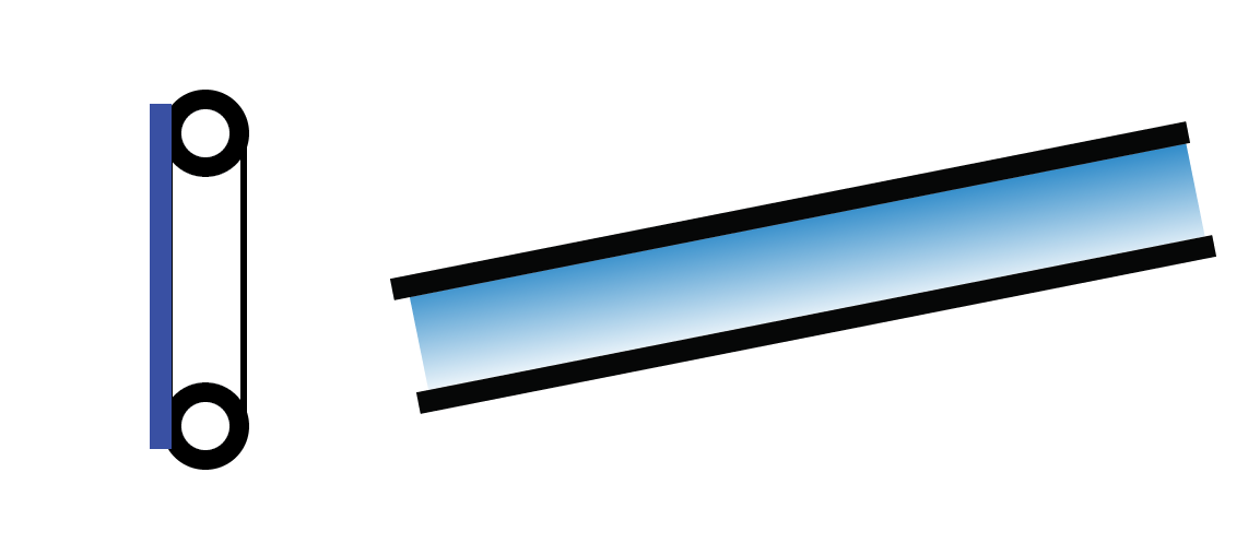
The spar is made from two parallel carbon tubes and overlaid with fiberglass. The above is a simple depiction of the spar, the blue is the fiberglass, the black is the carbon fiber tubes. The trick is how to hold the carbon fiber tubes in place while the fiberglass is being applied.
I route a piece of foam with the spar dimensions. This can be done by making a “V” cut into the foam and then pressing the carbon fiber tube into the “V” to form fit the trough. But, if you really wild and crazy, you can spend days on end developing hot wire cutting tools.
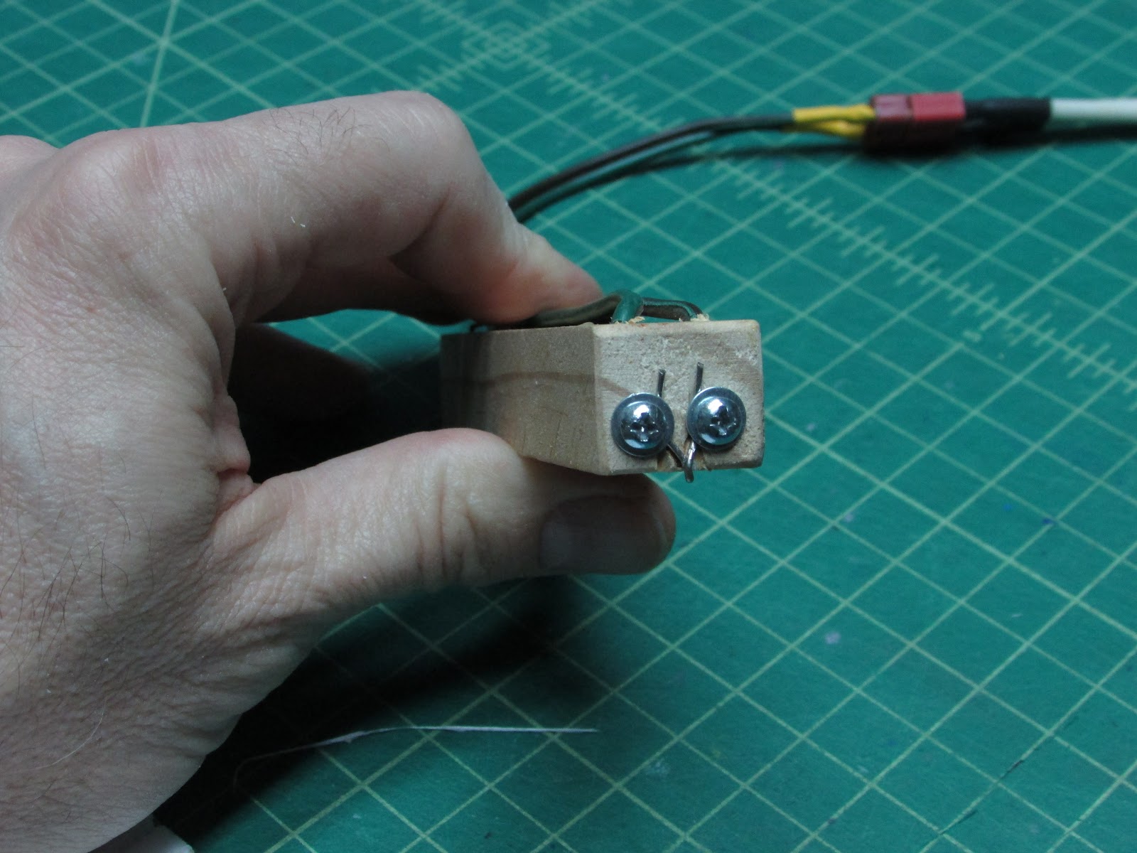
This is my 1.5 mm wide/deep hot wire trough tool.
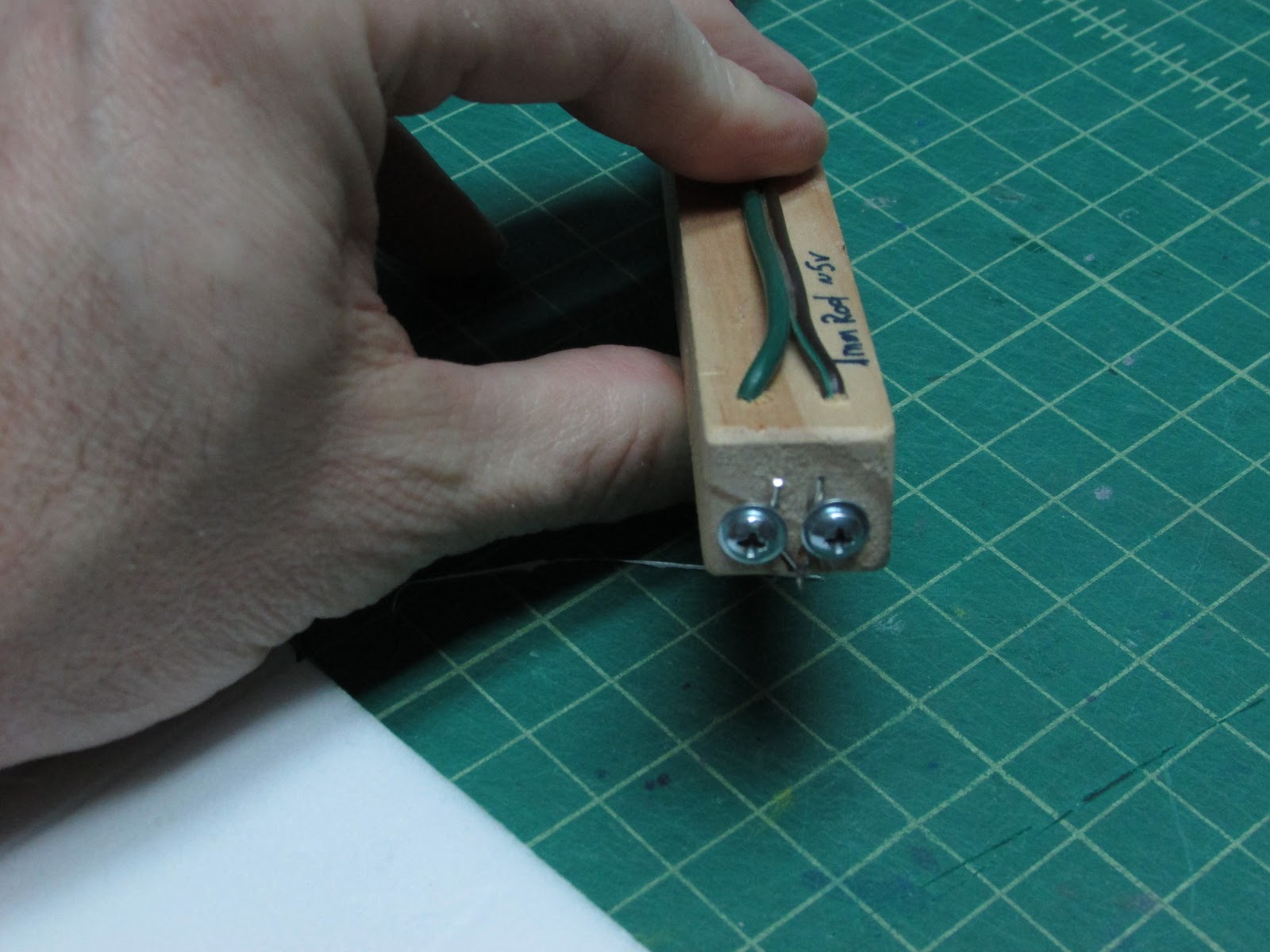
It was made by drilling two holes down from the top and then attaching Jacob’s Online nichrome wire to the end using servo screws. I hook this up to my hot wire cutting power supply and cut foam.
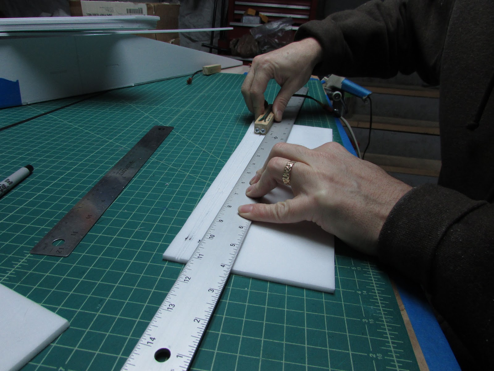
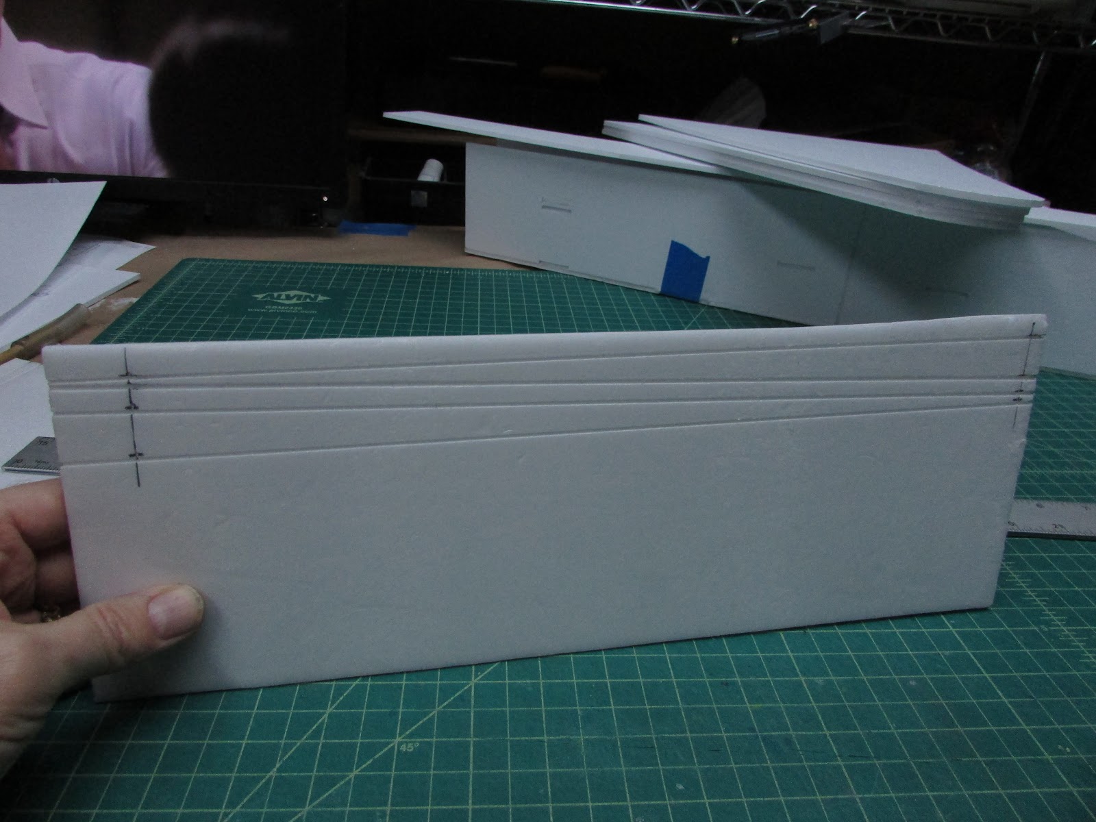
Lay a ruler along the lines needed to be troughed, turn on the power and slowly pull the hot wire cutter along the foam.
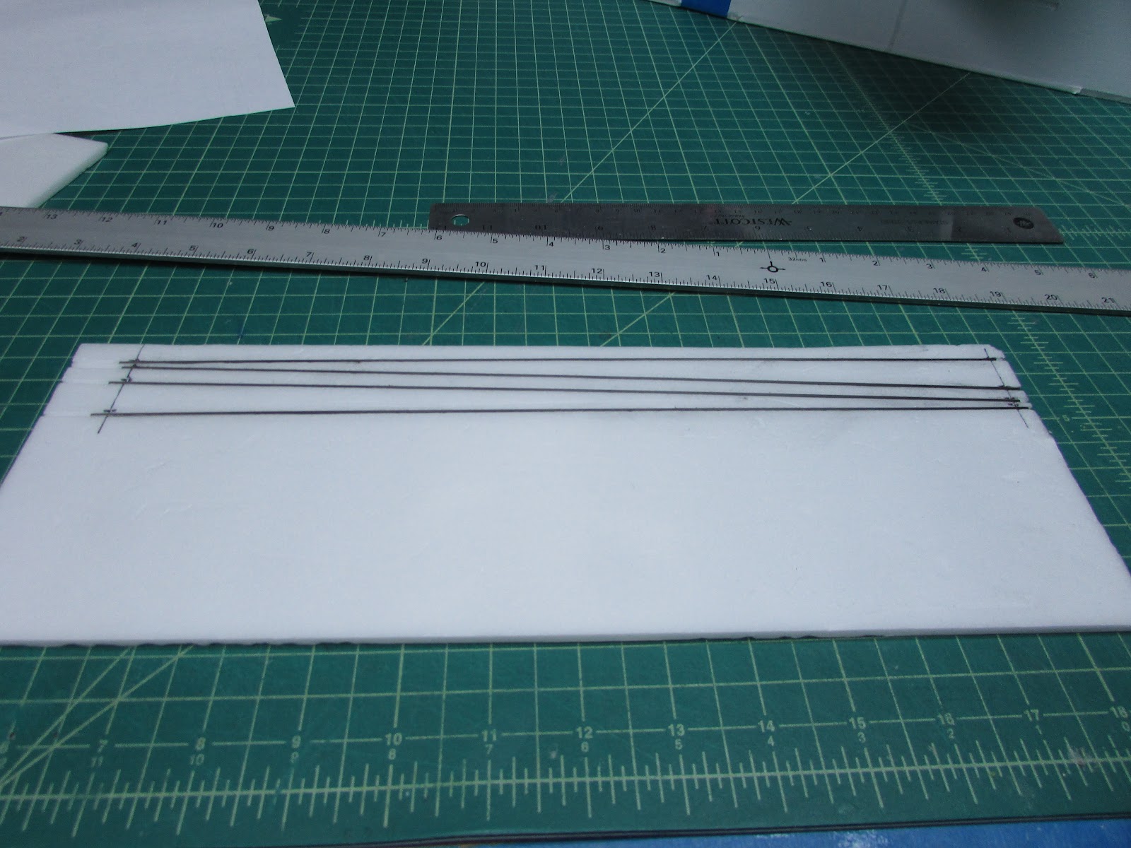
Gently sand the carbon fiber tubes and lay them in the troughs.
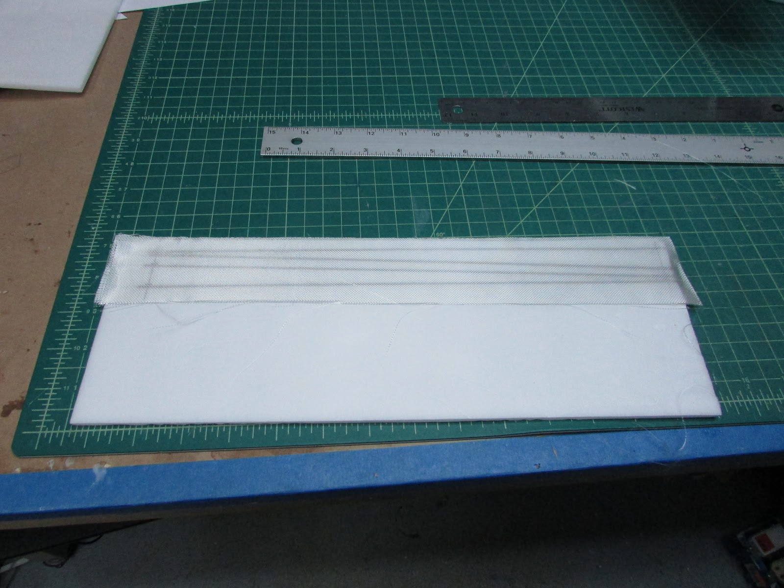
Overlay the setup with fiberglass cloth.
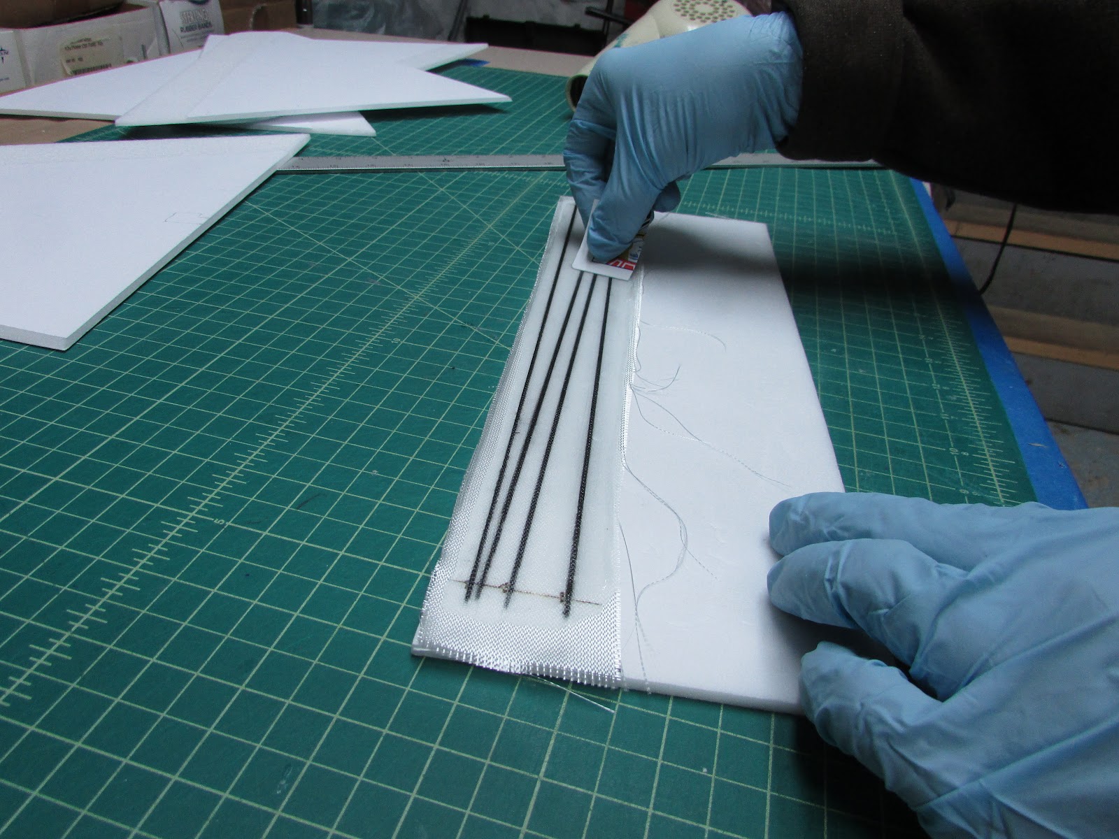
Wet out with epoxy resin.
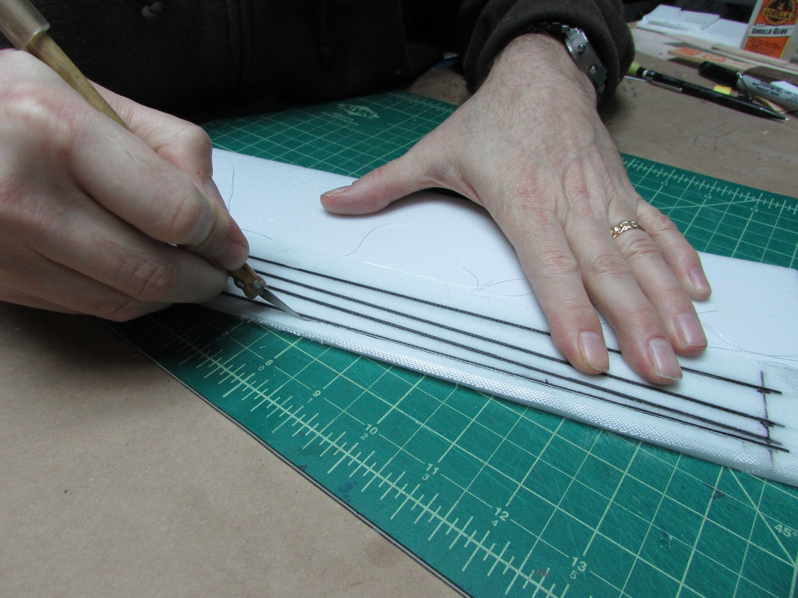
After it is cured, cut out the spars and sand off the rough edges.
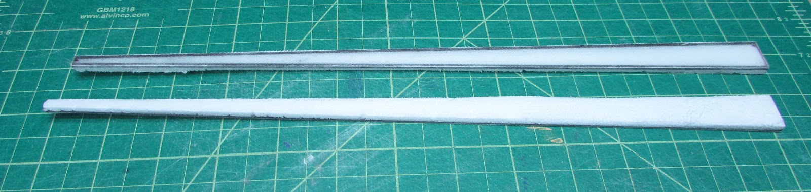
I left the foam on because it is easier to glue to the wing with a little bit of foam to give it some thickness.
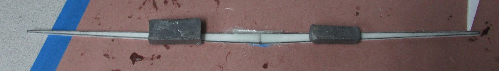
If my wings did not have dihedral, I would have made the trough mold with one long trough for the bottom and two angled top troughs with a joint. But since this would have dihedral, the two spar halves need to be joined. Hold in place and fiberglass the joint.
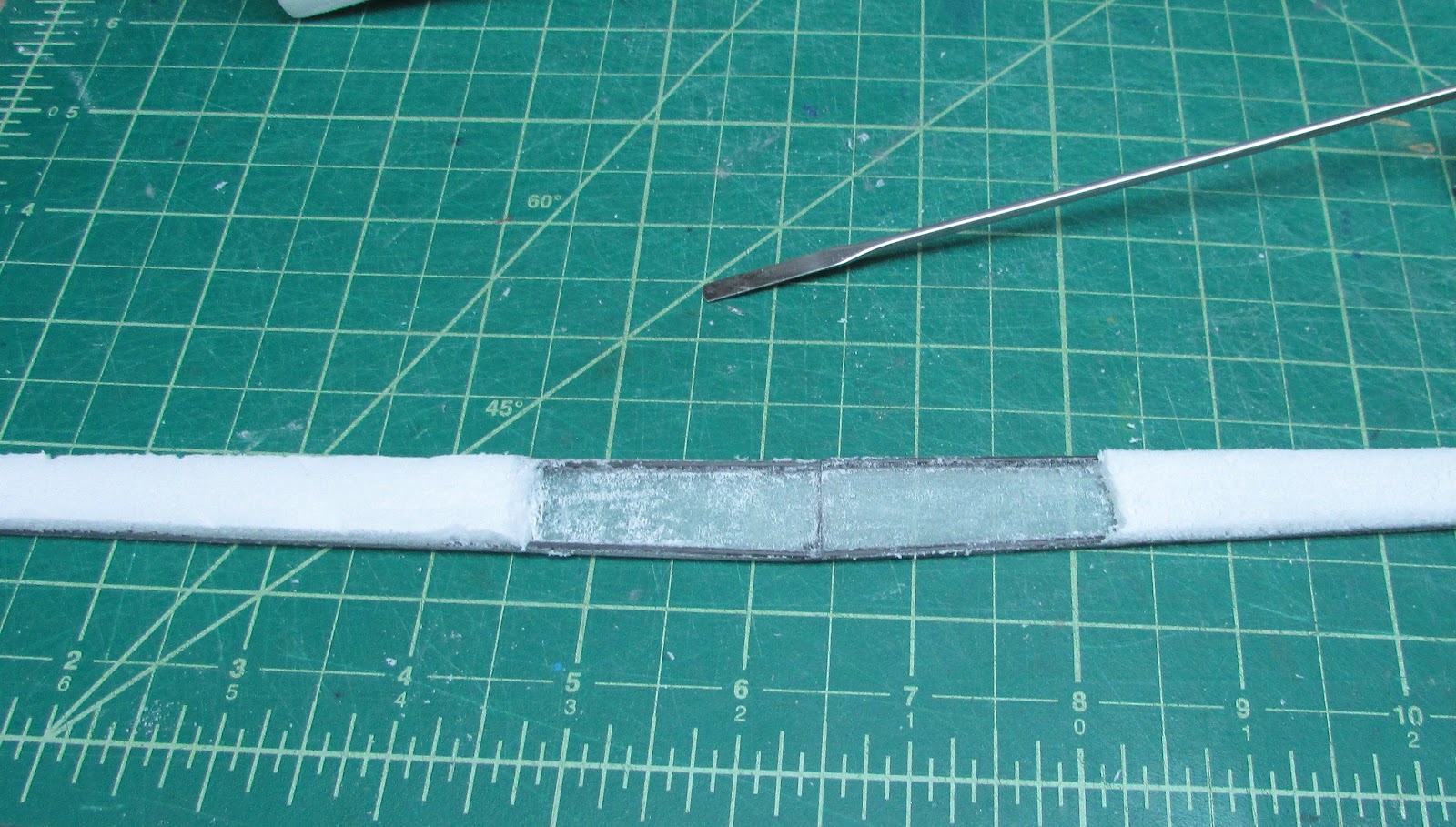
When it cures, turn over, scrape off the foam so that more fiberglass can be adhered directly to the carbon tubes and the fiberglass.
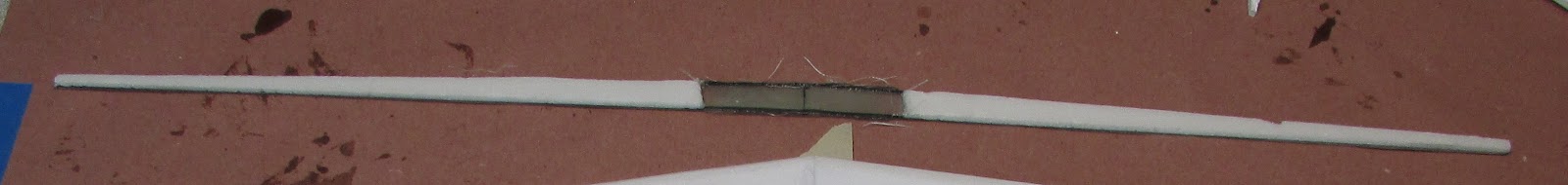
Sand off the excess fiberglass and the spar is done.
The bottom wing panels need to be prepared like the tail control surfaces. The leading edges were beveled in the typical FT style to make the leading edge with the top panel. The trailing edge of both top and bottom wing panels were beveled from a point 4 cm from the trailing edge to the trailing edge.
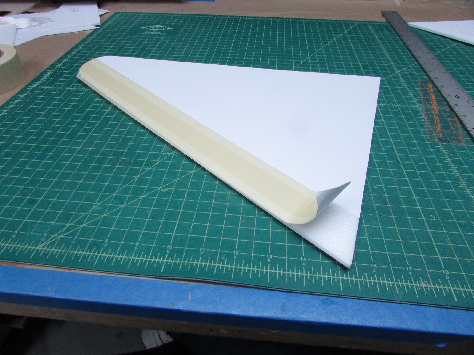
Since for this build I’m leaving the paper on the wings, to get the beveled trailing edge, I score the paper with a knife and then peel the paper. when the paper doesn’t peel off the foam nicely, a layer of masking tape tends to hold it together making the peel easier.
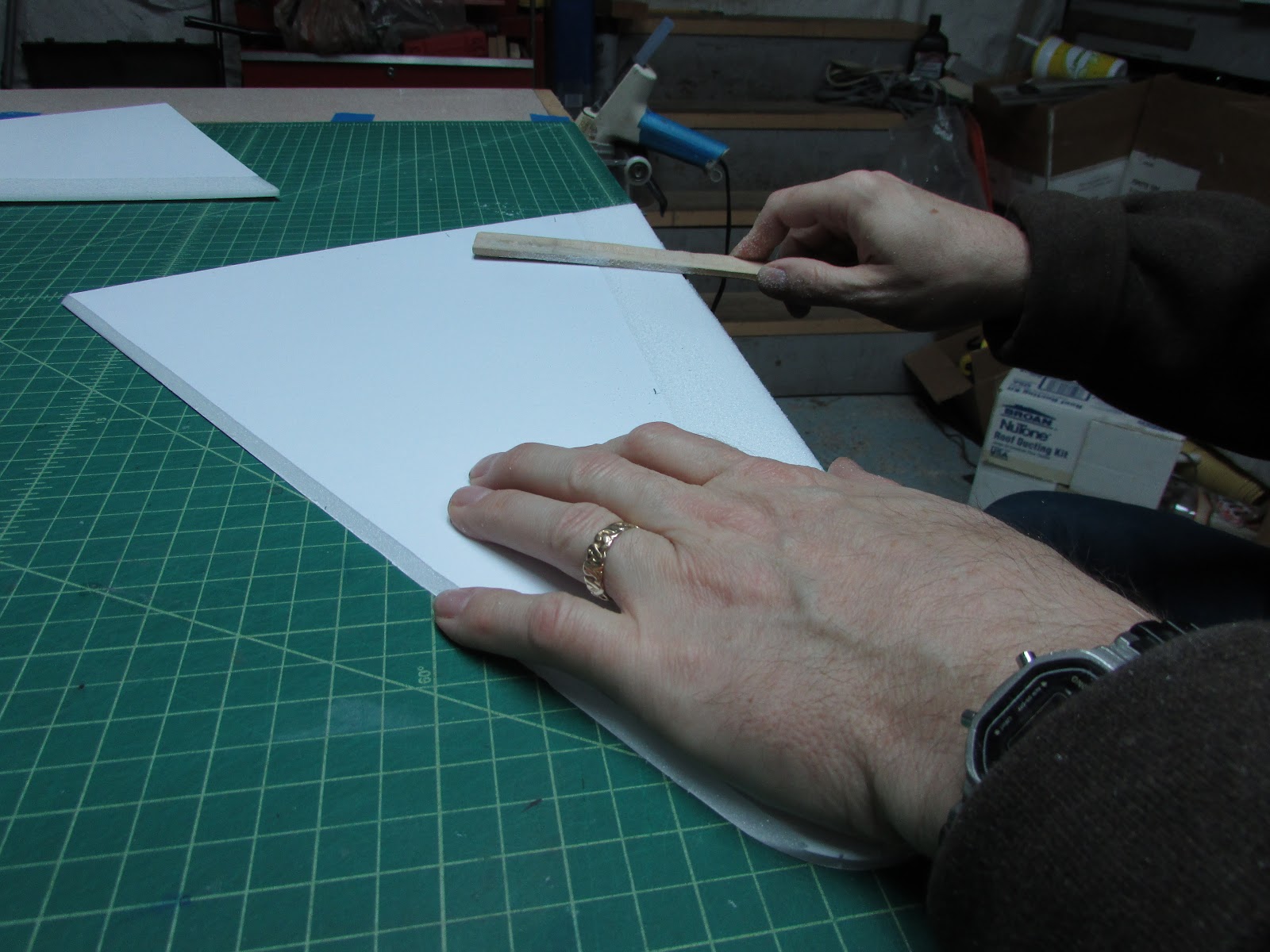
I use a paint stir stick with 80 grit sandpaper glued to it to shape the trailing edge tapper.
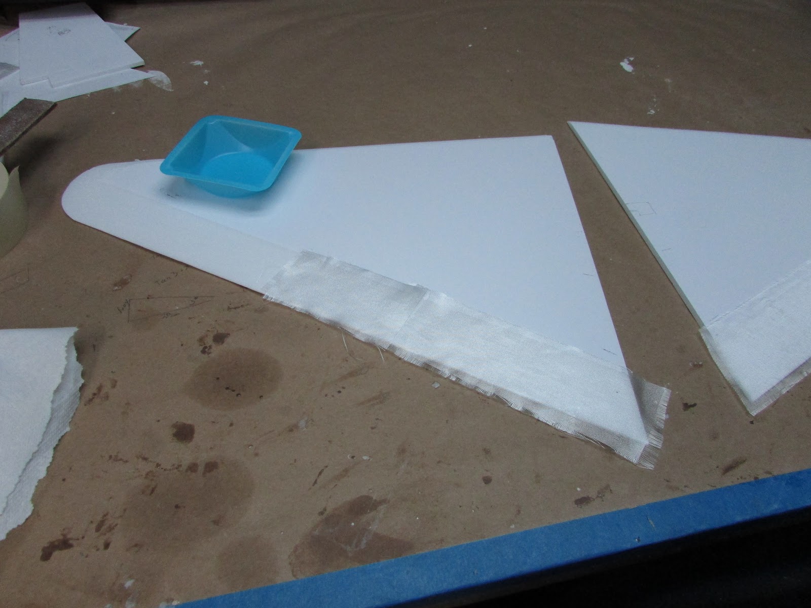
Put a fiberglass skin on the portion of the wing that will become the flap with 0.73 oz cloth to give the flap some strength.
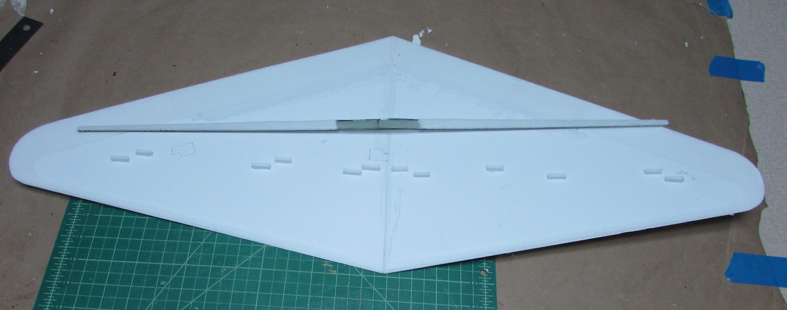
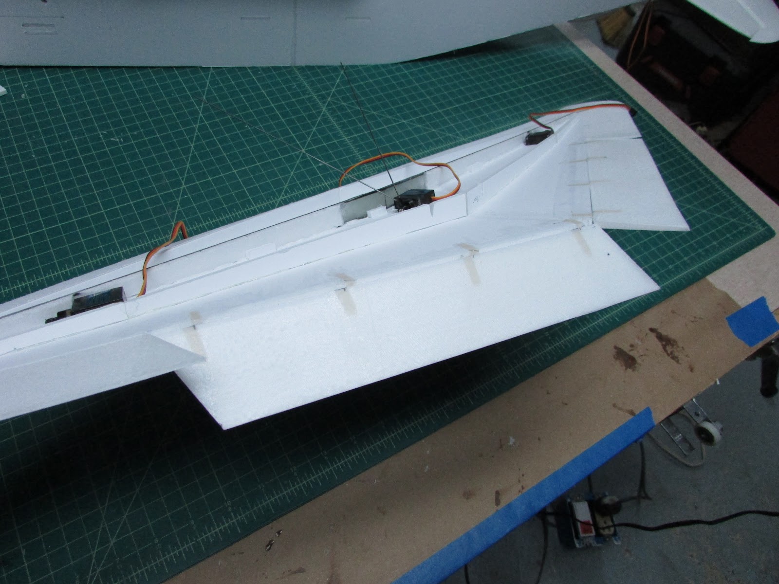
The bottom wing panels need to be attached to each other.
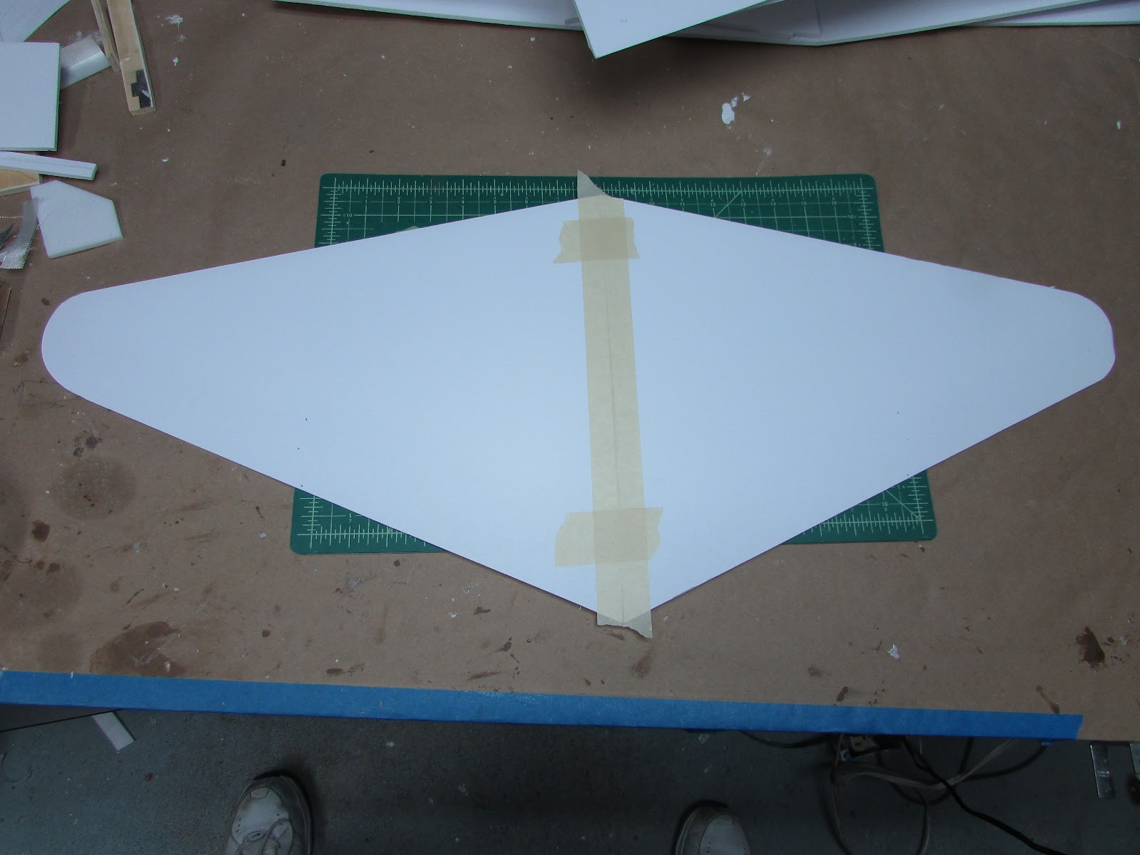
Tape them together with masking tape. Turn over and fold open, add Gorilla glue to the seam,
Hold it steady until the glue dries. Note that I have propped up the right wing to add a little dihedral.
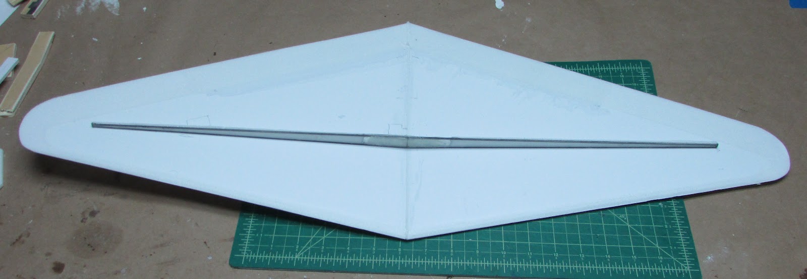
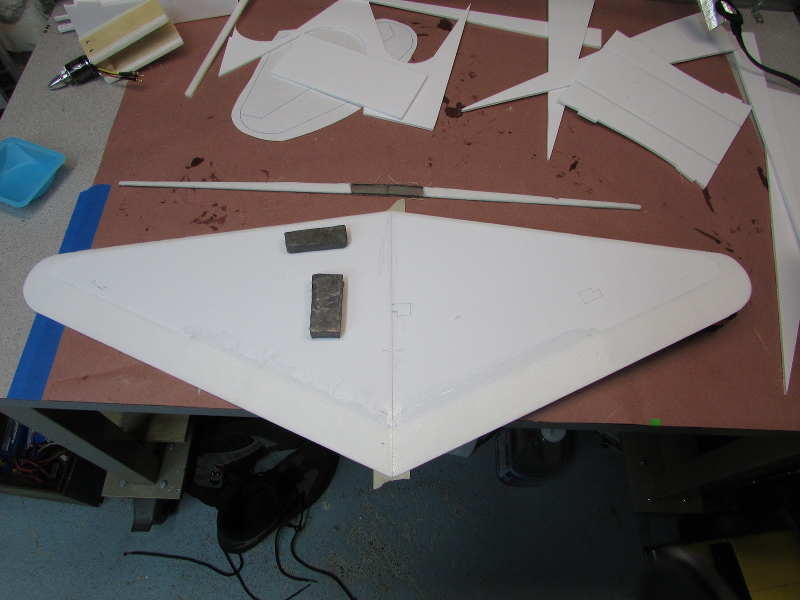
Now, attach the spar to the wing.
The little spar doesn’t balance on its own, so I hot glue pieces of foam (little handles) to hold it in position.
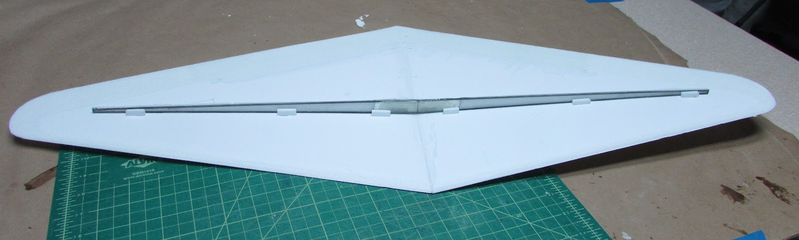
Nice! the spar is held in place with the little handles.
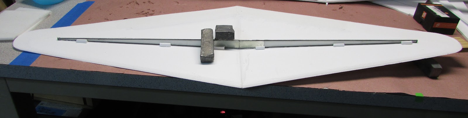
Make sure the spar is tight to the wing. Glue in place with Gorilla glue.
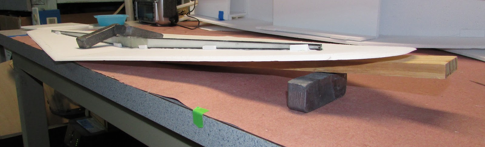
I use a little piece of scrap wood to support one wing half so the spar contacts the wing panels. Let it set until the glue cures. Glue the foam front spar in place. It is actually a spacer to give the wing some body since the root is so long.
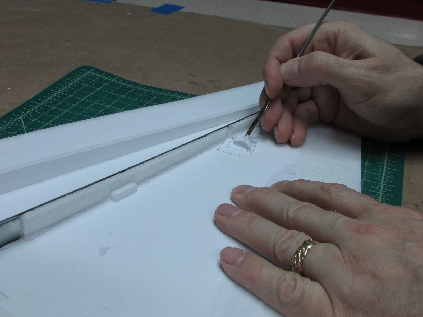
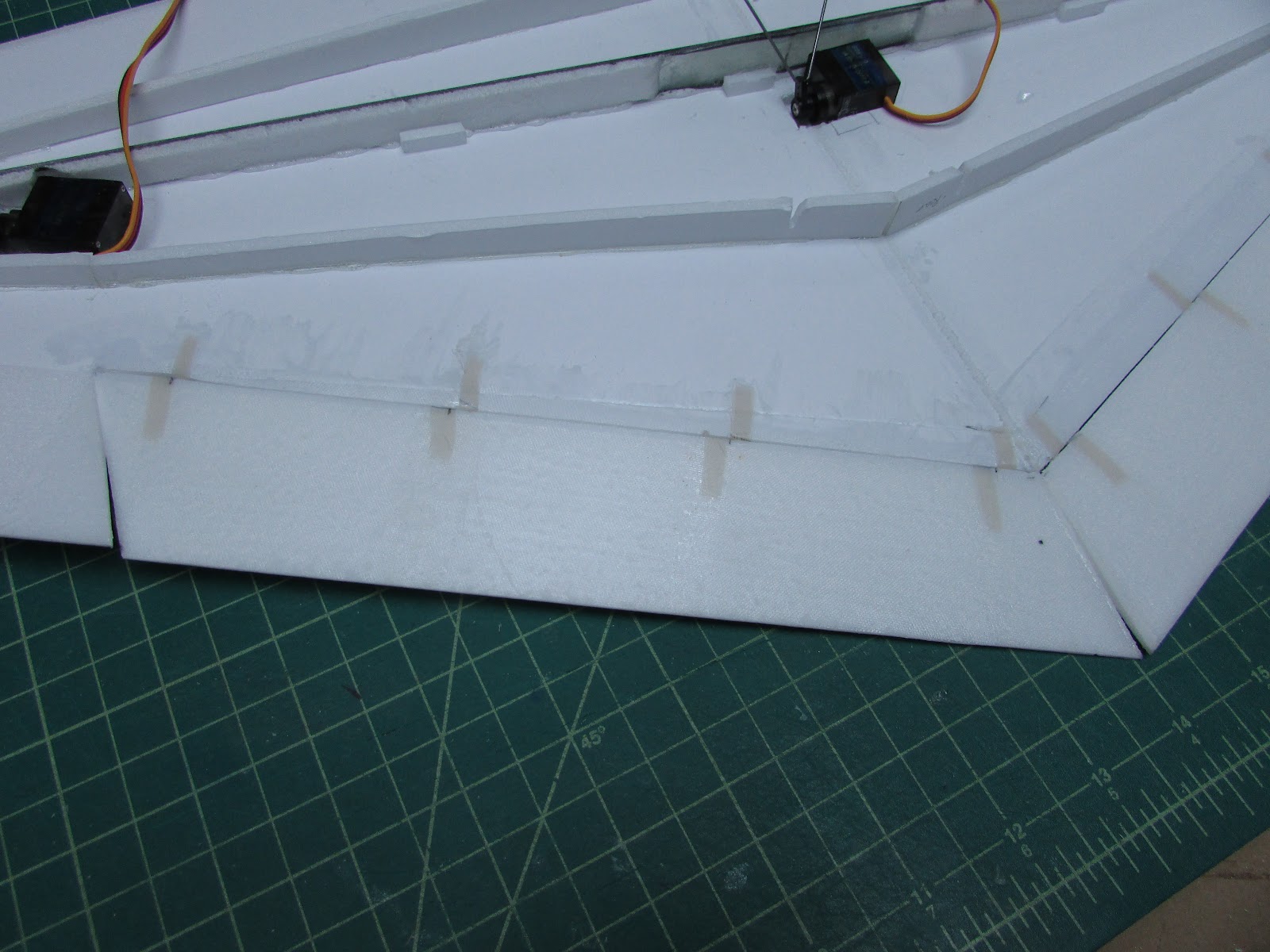
The placement for the aileron servos are gouged out of the bottom wing panel. Cut around where the servo is to be placed and use a rod of some sort to scrape the foam out. I tried not to damage the paper so the servo wouldn’t show on the other side.
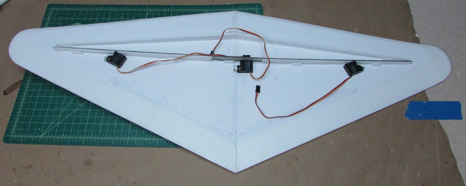
The servos are place in the wing, one for each aileron and one for the flaps.
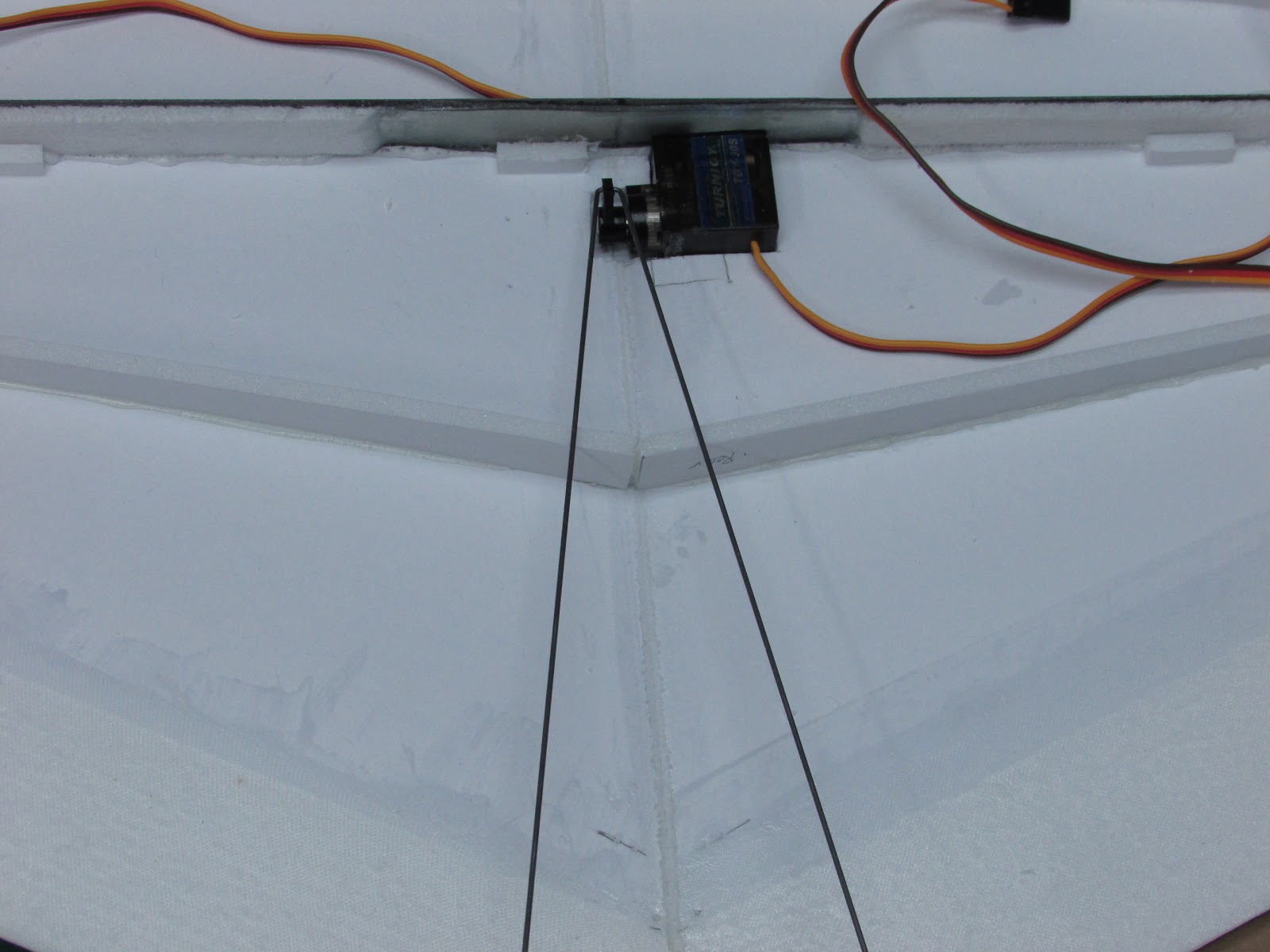
The flap servo controls both flaps using a “U” bend in the control rods.
Time to cut the flaps from the bottom panel. There is no need to bevel the hinge joint because these will be joined with a Jacob’s ladder joint.
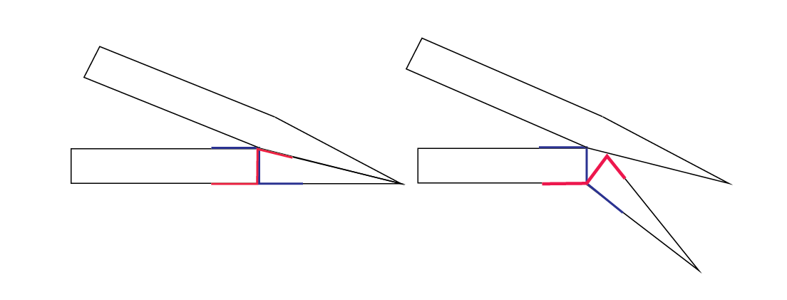
The blue and red are butt joint tape hinges and the flap pivots down and away from the top wing panel.
The tape hinges are polyester and attached with 30 minute epoxy.
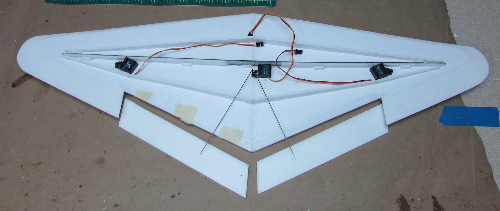
When the flap is deployed, it folds down along the bottom plate surface.
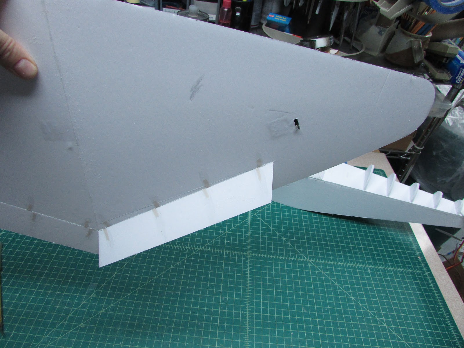
This is the bottom side. with one flap deployed and the other flat. Of course, when connected, they will operate together. On the right, the servo horn is poking through the bottom wing panel.
That is where it is right now.
Follow the progress Here:
Crosby CR4 HilldaFlyer Build 1/6th scale FT Style
The wings have been setting on the shelf for a while now. First I’ll show you how to make a spar, then the wing will go together. Not just any spar… a “I” beam carbon fiber spar.
The spar is made from two parallel carbon tubes and overlaid with fiberglass. The above is a simple depiction of the spar, the blue is the fiberglass, the black is the carbon fiber tubes. The trick is how to hold the carbon fiber tubes in place while the fiberglass is being applied.
I route a piece of foam with the spar dimensions. This can be done by making a “V” cut into the foam and then pressing the carbon fiber tube into the “V” to form fit the trough. But, if you really wild and crazy, you can spend days on end developing hot wire cutting tools.
This is my 1.5 mm wide/deep hot wire trough tool.
It was made by drilling two holes down from the top and then attaching Jacob’s Online nichrome wire to the end using servo screws. I hook this up to my hot wire cutting power supply and cut foam.
Lay a ruler along the lines needed to be troughed, turn on the power and slowly pull the hot wire cutter along the foam.
Gently sand the carbon fiber tubes and lay them in the troughs.
Overlay the setup with fiberglass cloth.
Wet out with epoxy resin.
After it is cured, cut out the spars and sand off the rough edges.
I left the foam on because it is easier to glue to the wing with a little bit of foam to give it some thickness.
If my wings did not have dihedral, I would have made the trough mold with one long trough for the bottom and two angled top troughs with a joint. But since this would have dihedral, the two spar halves need to be joined. Hold in place and fiberglass the joint.
When it cures, turn over, scrape off the foam so that more fiberglass can be adhered directly to the carbon tubes and the fiberglass.
Sand off the excess fiberglass and the spar is done.
The bottom wing panels need to be prepared like the tail control surfaces. The leading edges were beveled in the typical FT style to make the leading edge with the top panel. The trailing edge of both top and bottom wing panels were beveled from a point 4 cm from the trailing edge to the trailing edge.
Since for this build I’m leaving the paper on the wings, to get the beveled trailing edge, I score the paper with a knife and then peel the paper. when the paper doesn’t peel off the foam nicely, a layer of masking tape tends to hold it together making the peel easier.
I use a paint stir stick with 80 grit sandpaper glued to it to shape the trailing edge tapper.
Put a fiberglass skin on the portion of the wing that will become the flap with 0.73 oz cloth to give the flap some strength.
The bottom wing panels need to be attached to each other.
Tape them together with masking tape. Turn over and fold open, add Gorilla glue to the seam,
Hold it steady until the glue dries. Note that I have propped up the right wing to add a little dihedral.
Now, attach the spar to the wing.
The little spar doesn’t balance on its own, so I hot glue pieces of foam (little handles) to hold it in position.
Nice! the spar is held in place with the little handles.
Make sure the spar is tight to the wing. Glue in place with Gorilla glue.
I use a little piece of scrap wood to support one wing half so the spar contacts the wing panels. Let it set until the glue cures. Glue the foam front spar in place. It is actually a spacer to give the wing some body since the root is so long.
The placement for the aileron servos are gouged out of the bottom wing panel. Cut around where the servo is to be placed and use a rod of some sort to scrape the foam out. I tried not to damage the paper so the servo wouldn’t show on the other side.
The servos are place in the wing, one for each aileron and one for the flaps.
The flap servo controls both flaps using a “U” bend in the control rods.
Time to cut the flaps from the bottom panel. There is no need to bevel the hinge joint because these will be joined with a Jacob’s ladder joint.
The blue and red are butt joint tape hinges and the flap pivots down and away from the top wing panel.
The tape hinges are polyester and attached with 30 minute epoxy.
When the flap is deployed, it folds down along the bottom plate surface.
This is the bottom side. with one flap deployed and the other flat. Of course, when connected, they will operate together. On the right, the servo horn is poking through the bottom wing panel.
That is where it is right now.
Follow the progress Here:
Crosby CR4 HilldaFlyer Build 1/6th scale FT Style
Loving this.
Similar threads
- Replies
- 354
- Views
- 54K
- Replies
- 82
- Views
- 17K
- Replies
- 139
- Views
- 23K