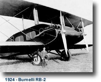
The Remington Bernelli RB-2
INSPIRATION
I watched this video... (Starting at the plane of interest)
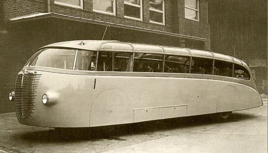
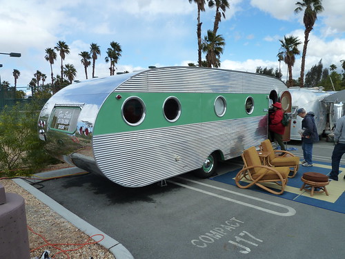
Then was tickled by the flying Camper look to it. (I am gearing up to head out on a camping trip this weekend)

HISTORY
From Wiki:
The Burnelli RB-1,
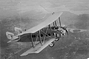
often known as the Remington-Burnelli Airliner, was an American passenger biplane from 1920, designed by Vincent Burnelli.[1][3] It incorporated Burnelli's lifting-body design. Following several more conventional designs during the WWI years, Burnelli came up with the idea of a lifting body: an airfoil-shaped fuselage that could be used to generate up to 50% of the lift, improving performance, due to reduced wing area and fuel consumption.
The RB-1's body contributed about 27% of the total lifting area and was designed to support about 15% of its weight. The fuselage was built around plywood frames and was clad in corrugated duralumin. The two pilots were situated in a pair of open cockpits, each with a mechanic seated by his side. Its pair of Liberty engines were immediately in front of these cockpits, largely buried in the leading edge of the body but accessible from the cockpits. The body width of 14 ft (4.27 m) placed the engines only 10 ft 4 in (3.15 m) apart, with about 1 in (25 mm) clearance between propeller tips. The cabin housed up to 30 passengers. At the fixed "trailing edge" of the fuselage small twin fins mounted above its sides carried balanced rudders and short, mid-fuselage mounted tailplanes carried balanced elevators.[1]
It was a single bay equal span biplane, with simple parallel interplane struts and without stagger. The wings were wooden structures, fabric covered. The ailerons carried on both upper and lower wings had prominent tip balances.[1]
The RB-1 flew for the first time on 21 June 1921 from Curtiss Field, Long Island, piloted by Bert Acosta[1] and William P. Sullivan.[citation needed] Its performance was considered acceptable. However, the first model produced was badly damaged while on the ground during a storm.
Burnelli RB-2
Design and development[edit]
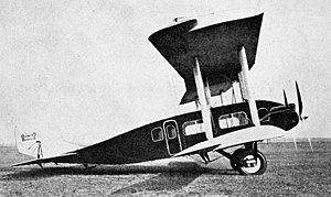
The RB-2 was based on the earlier RB-1 airliner, it had improved control surfaces and was powered by two 650 hp Galloway Atlantic piston engines.[4] It had a corrugated metal construction with a dural skin giving it an empty weight of 5 tons.[4] The passenger cabin could be fitted with 25 seats or used for freight.[4]
In 1925 the aircraft was used by the Hudson Motor Car Company as a flying showroom for the Essex automobile.[5]
PLANS
Here are links to the site with the balsa plans: http://www.aircrash.org/burnelli/pdf/mod_rb2.pdf
I had a few moments and all of a sudden had this draft plan set:
 v. Beta.01
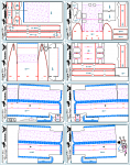 v. Beta.02 improvements: tabs & slots added, along with part labels, and a rough fuselage parts assembly diagram)
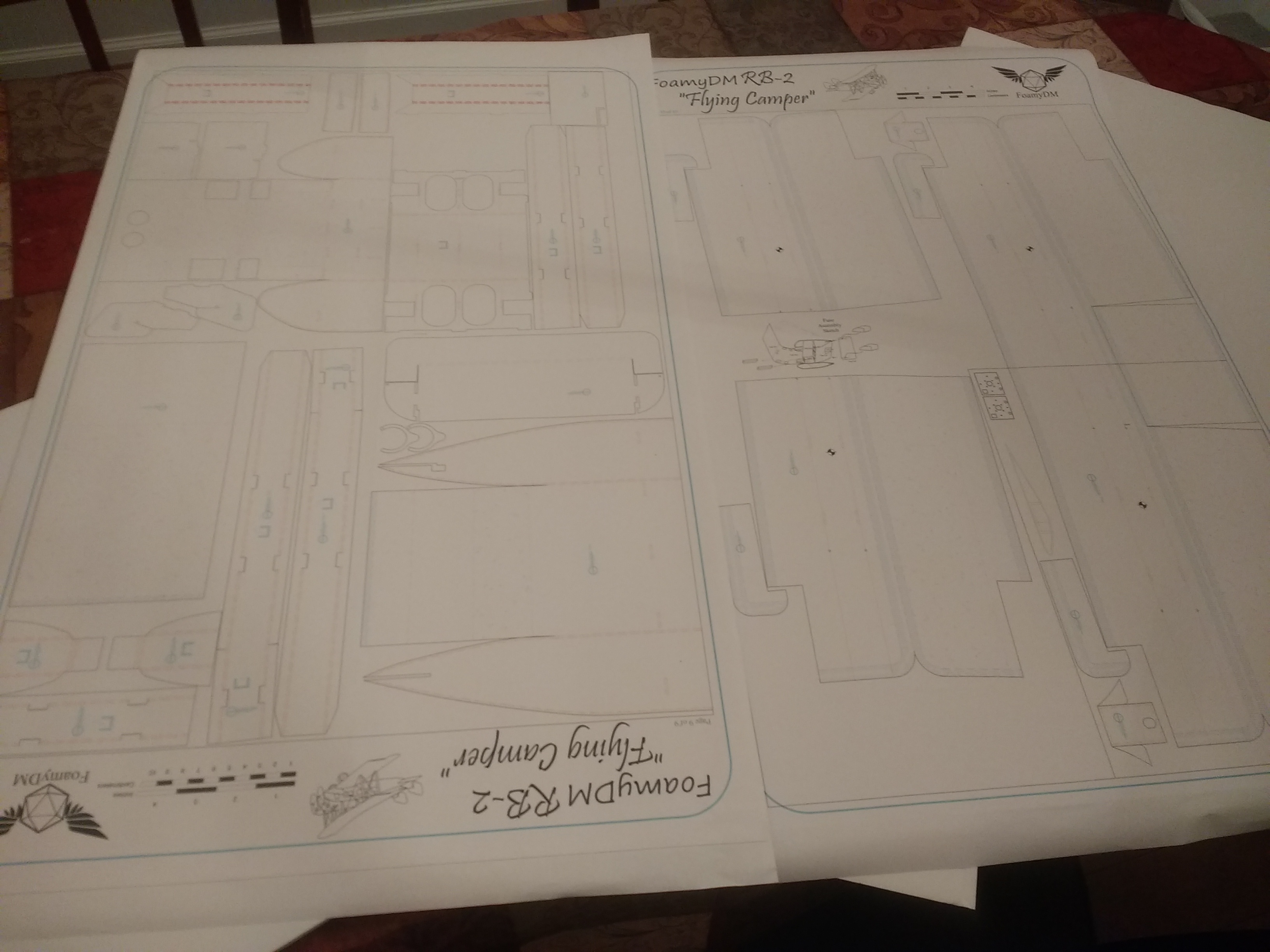
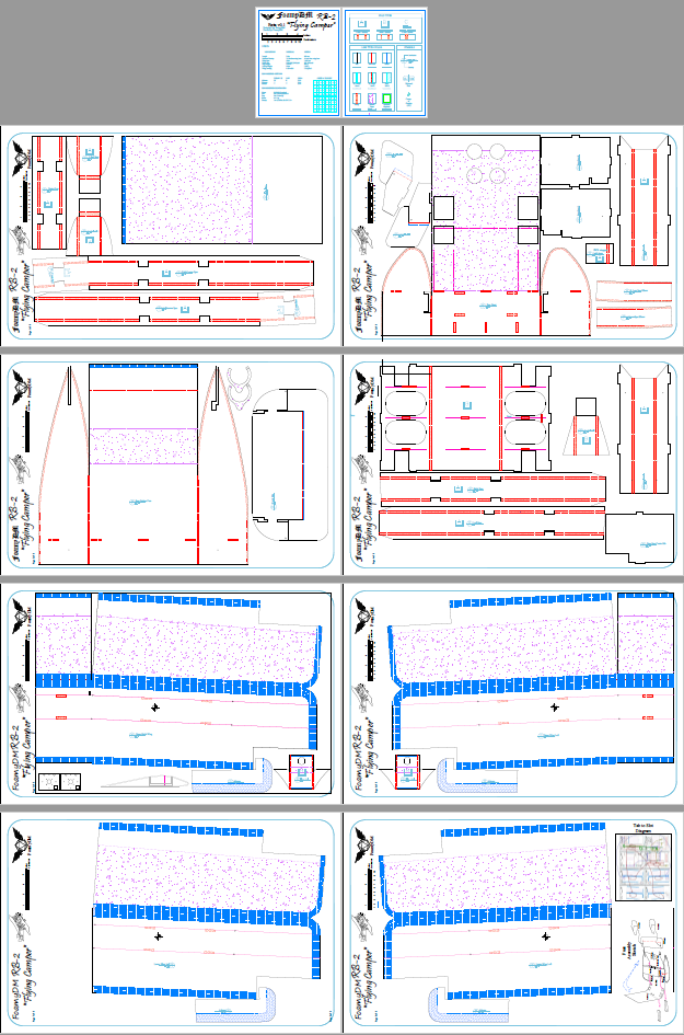
Full Size Plans V1.0
Linked are the Resource posted plans. These are complete with Tab-Slot references, and build diagrams The build has been tested at 1/2 scale.
FT RESOURCE LINK
DESIGN & BUILD
This craft is set to be a twin C-pack motor system using 4 to 6-9g servos, and 10x4.7 slop fly props or 9x6s. This should have ample room for Batteries and weight Capacity to make them large. @jpot1 has graciously accepted the torch of building this unusual piece of history, from my designs, and try and get it flying. While i plan to try a 50% A/F-pack version with 5" props, It will be low on the priority list.
When looking at the Wing loading... it should be stupidly light.
Here are the projected stats:

MAIDEN
Flight has occurred. it was tail-heavy and resulted in a crash disabling the craft temporarily.
Lessons Learned - Future Improvement
Include threaded cross-bracing to strengthen the wings. In the large C-pack version, have them able to be clipped and un-clipped so the wings can be removed simply.

INSPIRATION
I watched this video... (Starting at the plane of interest)
Then was tickled by the flying Camper look to it. (I am gearing up to head out on a camping trip this weekend)


HISTORY
From Wiki:
The Burnelli RB-1,

often known as the Remington-Burnelli Airliner, was an American passenger biplane from 1920, designed by Vincent Burnelli.[1][3] It incorporated Burnelli's lifting-body design. Following several more conventional designs during the WWI years, Burnelli came up with the idea of a lifting body: an airfoil-shaped fuselage that could be used to generate up to 50% of the lift, improving performance, due to reduced wing area and fuel consumption.
The RB-1's body contributed about 27% of the total lifting area and was designed to support about 15% of its weight. The fuselage was built around plywood frames and was clad in corrugated duralumin. The two pilots were situated in a pair of open cockpits, each with a mechanic seated by his side. Its pair of Liberty engines were immediately in front of these cockpits, largely buried in the leading edge of the body but accessible from the cockpits. The body width of 14 ft (4.27 m) placed the engines only 10 ft 4 in (3.15 m) apart, with about 1 in (25 mm) clearance between propeller tips. The cabin housed up to 30 passengers. At the fixed "trailing edge" of the fuselage small twin fins mounted above its sides carried balanced rudders and short, mid-fuselage mounted tailplanes carried balanced elevators.[1]
It was a single bay equal span biplane, with simple parallel interplane struts and without stagger. The wings were wooden structures, fabric covered. The ailerons carried on both upper and lower wings had prominent tip balances.[1]
The RB-1 flew for the first time on 21 June 1921 from Curtiss Field, Long Island, piloted by Bert Acosta[1] and William P. Sullivan.[citation needed] Its performance was considered acceptable. However, the first model produced was badly damaged while on the ground during a storm.
Burnelli RB-2

- Role Biplane freighter
- National origin United States
- Manufacturer Burnelli
- Designer Vincent Burnelli
- First flight 1924
- Number built 1
- Developed from Burnelli RB-1
Design and development[edit]
The RB-2 was based on the earlier RB-1 airliner, it had improved control surfaces and was powered by two 650 hp Galloway Atlantic piston engines.[4] It had a corrugated metal construction with a dural skin giving it an empty weight of 5 tons.[4] The passenger cabin could be fitted with 25 seats or used for freight.[4]
In 1925 the aircraft was used by the Hudson Motor Car Company as a flying showroom for the Essex automobile.[5]
PLANS
Here are links to the site with the balsa plans: http://www.aircrash.org/burnelli/pdf/mod_rb2.pdf
I had a few moments and all of a sudden had this draft plan set:
 v. Beta.01
 v. Beta.02 improvements: tabs & slots added, along with part labels, and a rough fuselage parts assembly diagram)
Full Size Plans V1.0
Linked are the Resource posted plans. These are complete with Tab-Slot references, and build diagrams The build has been tested at 1/2 scale.
FT RESOURCE LINK
DESIGN & BUILD
This craft is set to be a twin C-pack motor system using 4 to 6-9g servos, and 10x4.7 slop fly props or 9x6s. This should have ample room for Batteries and weight Capacity to make them large. @jpot1 has graciously accepted the torch of building this unusual piece of history, from my designs, and try and get it flying. While i plan to try a 50% A/F-pack version with 5" props, It will be low on the priority list.
When looking at the Wing loading... it should be stupidly light.
Here are the projected stats:

MAIDEN
Flight has occurred. it was tail-heavy and resulted in a crash disabling the craft temporarily.
Lessons Learned - Future Improvement
Include threaded cross-bracing to strengthen the wings. In the large C-pack version, have them able to be clipped and un-clipped so the wings can be removed simply.
Last edited:





![1188135[11].jpg](/proxy.php?image=https%3A%2F%2Fimgprod65.hobbylobby.com%2Fsys-master%2Fmigrated%2Fhcd%2Fh7c%2Fh00%2F9195471732766%2F1188135%5B11%5D.jpg&hash=9f1ab4640942e1ab1eac6d6c369ac4d2)


