JohnRambozo
Posted a thousand or more times
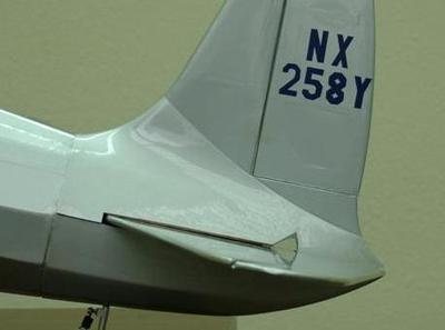
Foolish as it may be, I can't stop thinking about the Hughes H-1, so it must be made into foam.
The foolish choice is to try to make nearly scale race wings for the maiden, rather than the wider cross-country wings. Its just such a streamlined design and an amazing piece of aviation history.
I have a rough draft that I am currently cutting based on some old balsa plans. I am using a power pod sized rectangular center with a lot of formers along the length. I'm going to try a poster board skin first, then see what I can add for strength. There are 5 formers to get the shape of the front cowl, and another 9 or 10 for the rest of the fuse shape.
Overall dimensions:
Wingspan - 28 inches shown (32 inches in plans)
Fuse Length - 29 inches
Plans are for the more practical 32 inch wingspan used to break the cross-country record.
The larger wings have not been tested as this February 2015 in New England has been the coldest on record and the snowiest I have ever seen. I figure if a 28 inch wingspan flies, 32 inches will fly a little slower, but not too slow.
If and when you build your own, please share the experience with everyone here!
If you run into any bugs, share those as well so I can update the plans.
Full Plans (with Edits after ClearSkiesCalmWinds tested) in the links below:
jrHughes H-1 Cross Country and Racing Wings - Page 1/2
jrHughes H-1 Cross Country and Racing Wings - Page 2/2
Links updated to include spar and servo slots. Now includes both Cross Country and Racing wings!
Build Log Starts Here:
After cutting the wings I was very concerned they would be too small. To put my mind at ease I found this guide on calculating wing loading: How to Calculate the Wing Loading of a Flying Model Aircraft
Based on a trapezoidal segmentation of the wing to measure area I've found I need to keep it under 800 grams AUW to fly heavy. 800 grams puts me just over the 25 oz/sq ft limit. I know I'm mixing measures but I had to convert to oz/sq ft based on the chart I found showing suggested wing loading. If I can keep it down to 700 grams, I only have 21 oz/sq ft. While still heavy, it should be manageable.
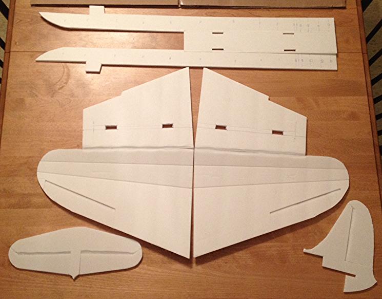
Here are the wings, the sides of the fuse and the tail feathers cut out.
The fuse is going to be just about 2 inches shorter than the FT Spitfire. These wings are much smaller.
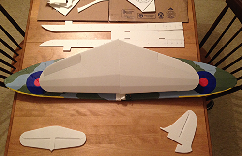
Test fitting the formers (now glued in place) and the power pod. Its a tight fit, but it fits!

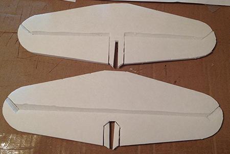
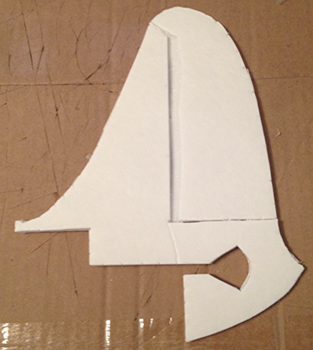
I opted for a 1 piece elevator to save weight on the solutions needed to address a 2 piece elevator. I was even able to keep that signature look intact. The H.Stabs are both the same size, its just the perspective angle that makes them look different. First attempt on top, current on the bottom.
I'm running into too many problems with the fuse and am redesigning based on this... simplifying where possible:
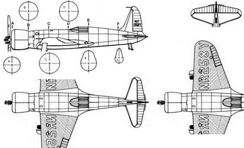
The wing remains unchanged. It is nearly identical to what I would have come up based on the new 3 view drawing. I'm happy with the subtle changes to the tail. Changes to the fuse are pretty drastic. Basically a complete redesign to allow for simple wing placement and fewer formers. The center blue line on the fuse bottom is to help center the wings. The blue lines on the fuse mark former placement. Removable nose/cowl and former shapes coming soon.
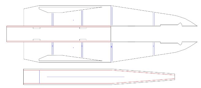
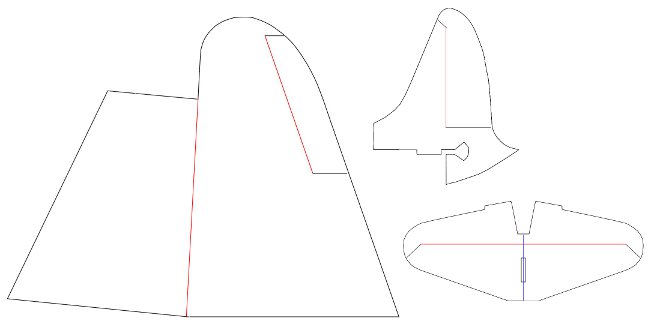
Most recent plan layout showing formers and cowl supports.

Upate 9/11/14 - I finished cutting the foam and got the fuse together including the break-away cowl. Here's the play by play. I'll add the text soon. The wings and tail feathers are just test fit, everything else is glued in place.

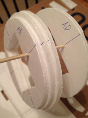
Each piece of the cowl is indicated by the double letters AA-AE. There are red dots on the plans that mark where the skewer should go through for perfect alignment. I recommend carefully poking all 4 holes on each piece to center and test fit the alignment before applying glue.
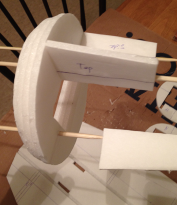
Do the same for the supports that go between AD and AE.
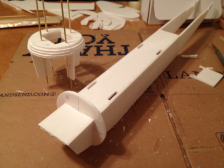
I borrowed the main fuse assembly style from nerdnic. Place it upside down on the table and use a 90 degree when gluing the B style fold. Make sure its good and solid before moving on. Then install the B former first, followed by AE including the pieces on the underside. Use your guidelines that you should have transferred from the planes for alignment.

Make sure you put your bends on the blue lines for the fuse bottom before installing. Test fit front to back before gluing. Start gluing by just doing the front piece up to the first bend. It should butt up against the back side of the B former bottom piece.

Now glue the bottom back just to the E former bend.
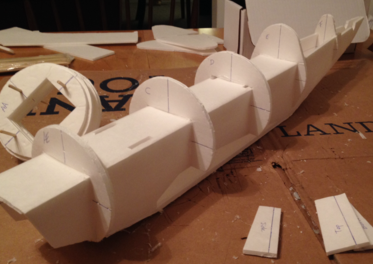
Glue in the rest of the formers C - F, then finish off the bottom of the fuse.
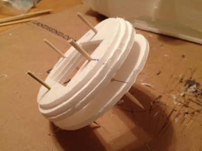
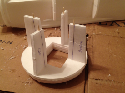
You'll want only this much of the skewer exposed to give enough grip to stay in place when its lightly glued. This allows for a break-away cowl. It should preserve the fuse in case of a bad landing. I'm sure I'll find out soon enough.
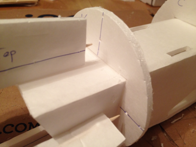
Slide the skewers into the alignment holes.
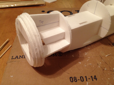
I only put a tiny dab of glue on the left and right side where the support touches AE for minimal resistance in a crash.
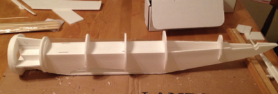
Main fuse complete.
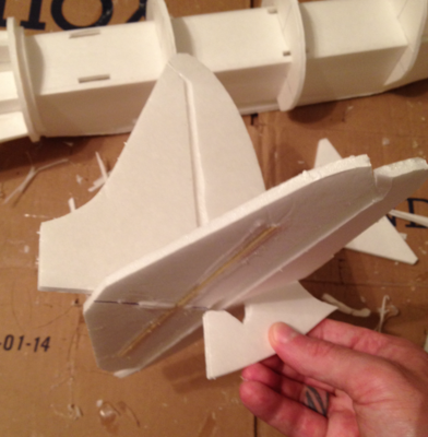
I use nerdnic's horizontal stabilizer spar trick. Make sure you're utilizing your 90 degree piece to keep your tail good and square when gluing.
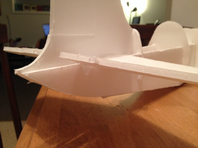
Detail of the aft section.
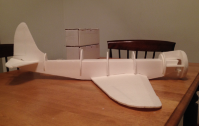
Wings are still in the final design stage but I wanted to make sure they fit in my wing mount slots. They're perfectly snug and will get some dihedral when they are done.

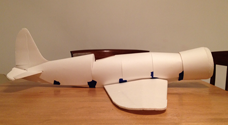
Profile view of first pass on the poster board, taped in place. Some slight adjustments need to be made at the seams, but it came together faster than I expected.
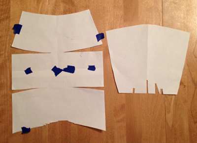
I approached each span between formers individually by wrapping with plain paper. I taped it in place then used a pencil to draw a line marking the former. Then cut along the line up to just less than the top center on both sides. Tape the rear of the section you just cut into place, then start shaping the next span from that former to the following former. Hold in place and draw a line across the front former of that span to eliminate the overlap. Cut, tape, repeat. Make a 'break' every time there is a noticeable shape change between formers.
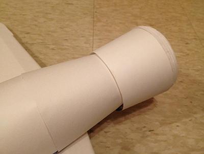
This subtle overlap is my favorite part.
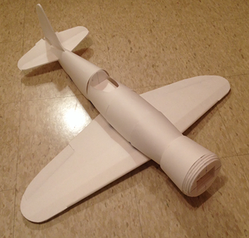
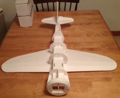
Again. Ignore the angle of the wings. The poster is pushing them down in this picture. I do think I could stand to reduce the size of formers C and D (over the wings) to get that slimmer H-1 look but I'm pretty happy with it so far.
At first glance it may appear I'm actually going backwards, but the wings were only test fit before. The following shows the process of installing the spar and servos, then completing and attaching the wings and tail.
I went with a tapered spar. Plans will be updated soon.
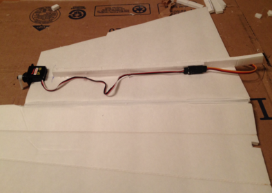
The wing is too thin to tuck the servo in, so I just made a servo-sized cutout. Put plenty of glue on every surface where the wing touches the servo. I finished by slathering a generous amount of glue right across the servo for maximum rigidity. Squeegee it lightly with a scrap of foam.
If you are paying attention you may also notice the aileron has been reduced to about half of the original size. There was no need for that much control surface on these tiny wings. This is actually more in line with the scale size, as well.
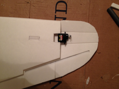
Finished wings with 6" servo extensions. I just used a 2.5 inch piece at one wingtip to give what looks to be scale dihedral.

As you can see, the dihedral is not too steep.
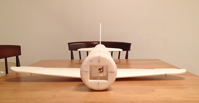
Wings and tail are in line. Tomorrow I will install the power pod and battery to find the ideal location for the rear servos. I want it to balance without adding extra weight if at all possible.
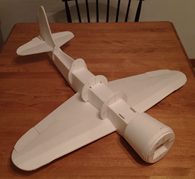
I removed the cowl to sand it with 220 grit sandpaper. It took more work than I expected but it was worth it.
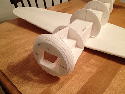
Power Pod mounts installed. Wow is it a tight fit. I had to trim the bottom cowl support down to make room for my ESC to fit through since its attached to the bottom of the power pod. It barely fits but it fits.
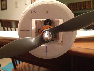
Removable wings are all set.
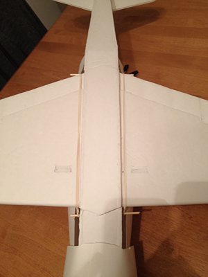
Everything you see is glued in place, finally. I still have to mount the rear servos. That's why the rear turtle deck is still off. I'm really happy with how its coming out now that everything is down tight.
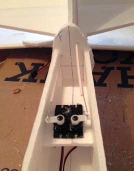
Servos are mounted in a little servo deck halfway between the E and F formers. It seemed like about the right place for where I wanted to put my battery in the pod (and it was).
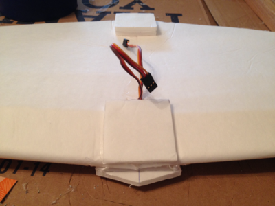
If you did the removable wings, you'll want to reinforce your wing mounts and center some squares on top of the wing to keep it from twisting while flying. I used a subway rewards card for the reinforcements. I'm running out of gift cards and rewards cards.
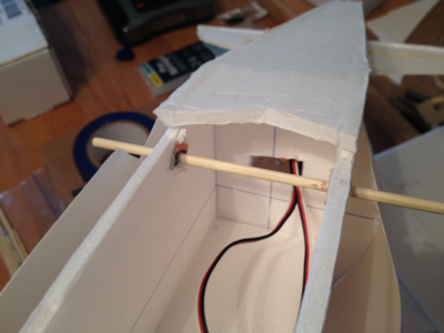
I used the same rewards card for the control horns and trimmed it up as best I could on the ground before gluing down the rear turtle deck.
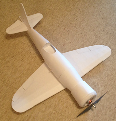
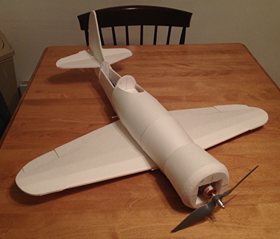
I just thought this was a cool angle that really makes it look like an H-1.
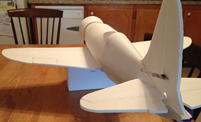
Look how stubby those wings are and how compact it is. Pocket rocket!
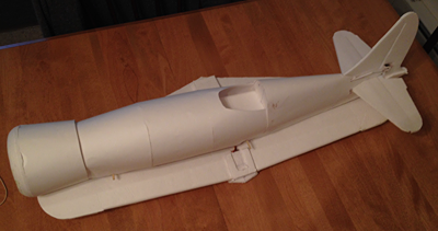
Unedited video of the maiden flight. Filmed and narrated by my 12 year old with some excited commentary from my 7 year old.
Lightly edited video of second flight on the same gusty/windy day with my 7 year old singing Puff the Magic Plane at the top of her lungs. Haha.
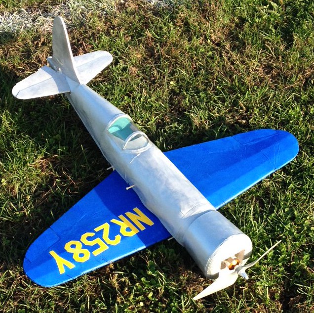
Well, its finally done. Repaired, painted, and ready to race. I'll update with the final plans. If anyone decides to build this, feel free to ask questions and please share pictures.
The foolish choice is to try to make nearly scale race wings for the maiden, rather than the wider cross-country wings. Its just such a streamlined design and an amazing piece of aviation history.
I have a rough draft that I am currently cutting based on some old balsa plans. I am using a power pod sized rectangular center with a lot of formers along the length. I'm going to try a poster board skin first, then see what I can add for strength. There are 5 formers to get the shape of the front cowl, and another 9 or 10 for the rest of the fuse shape.
Overall dimensions:
Wingspan - 28 inches shown (32 inches in plans)
Fuse Length - 29 inches
Plans are for the more practical 32 inch wingspan used to break the cross-country record.
The larger wings have not been tested as this February 2015 in New England has been the coldest on record and the snowiest I have ever seen. I figure if a 28 inch wingspan flies, 32 inches will fly a little slower, but not too slow.
If and when you build your own, please share the experience with everyone here!
If you run into any bugs, share those as well so I can update the plans.
Full Plans (with Edits after ClearSkiesCalmWinds tested) in the links below:
jrHughes H-1 Cross Country and Racing Wings - Page 1/2
jrHughes H-1 Cross Country and Racing Wings - Page 2/2
Links updated to include spar and servo slots. Now includes both Cross Country and Racing wings!
Build Log Starts Here:
After cutting the wings I was very concerned they would be too small. To put my mind at ease I found this guide on calculating wing loading: How to Calculate the Wing Loading of a Flying Model Aircraft
Based on a trapezoidal segmentation of the wing to measure area I've found I need to keep it under 800 grams AUW to fly heavy. 800 grams puts me just over the 25 oz/sq ft limit. I know I'm mixing measures but I had to convert to oz/sq ft based on the chart I found showing suggested wing loading. If I can keep it down to 700 grams, I only have 21 oz/sq ft. While still heavy, it should be manageable.
Here are the wings, the sides of the fuse and the tail feathers cut out.

The fuse is going to be just about 2 inches shorter than the FT Spitfire. These wings are much smaller.

Test fitting the formers (now glued in place) and the power pod. Its a tight fit, but it fits!

I opted for a 1 piece elevator to save weight on the solutions needed to address a 2 piece elevator. I was even able to keep that signature look intact. The H.Stabs are both the same size, its just the perspective angle that makes them look different. First attempt on top, current on the bottom.


I'm running into too many problems with the fuse and am redesigning based on this... simplifying where possible:

The wing remains unchanged. It is nearly identical to what I would have come up based on the new 3 view drawing. I'm happy with the subtle changes to the tail. Changes to the fuse are pretty drastic. Basically a complete redesign to allow for simple wing placement and fewer formers. The center blue line on the fuse bottom is to help center the wings. The blue lines on the fuse mark former placement. Removable nose/cowl and former shapes coming soon.


Most recent plan layout showing formers and cowl supports.

Upate 9/11/14 - I finished cutting the foam and got the fuse together including the break-away cowl. Here's the play by play. I'll add the text soon. The wings and tail feathers are just test fit, everything else is glued in place.


At first glance it may appear I'm actually going backwards, but the wings were only test fit before. The following shows the process of installing the spar and servos, then completing and attaching the wings and tail.
I went with a tapered spar. Plans will be updated soon.

The wing is too thin to tuck the servo in, so I just made a servo-sized cutout. Put plenty of glue on every surface where the wing touches the servo. I finished by slathering a generous amount of glue right across the servo for maximum rigidity. Squeegee it lightly with a scrap of foam.
If you are paying attention you may also notice the aileron has been reduced to about half of the original size. There was no need for that much control surface on these tiny wings. This is actually more in line with the scale size, as well.

Finished wings with 6" servo extensions. I just used a 2.5 inch piece at one wingtip to give what looks to be scale dihedral.

As you can see, the dihedral is not too steep.

Wings and tail are in line. Tomorrow I will install the power pod and battery to find the ideal location for the rear servos. I want it to balance without adding extra weight if at all possible.

I removed the cowl to sand it with 220 grit sandpaper. It took more work than I expected but it was worth it.

Power Pod mounts installed. Wow is it a tight fit. I had to trim the bottom cowl support down to make room for my ESC to fit through since its attached to the bottom of the power pod. It barely fits but it fits.

Removable wings are all set.

Everything you see is glued in place, finally. I still have to mount the rear servos. That's why the rear turtle deck is still off. I'm really happy with how its coming out now that everything is down tight.

Servos are mounted in a little servo deck halfway between the E and F formers. It seemed like about the right place for where I wanted to put my battery in the pod (and it was).

If you did the removable wings, you'll want to reinforce your wing mounts and center some squares on top of the wing to keep it from twisting while flying. I used a subway rewards card for the reinforcements. I'm running out of gift cards and rewards cards.


I used the same rewards card for the control horns and trimmed it up as best I could on the ground before gluing down the rear turtle deck.

I just thought this was a cool angle that really makes it look like an H-1.

Look how stubby those wings are and how compact it is. Pocket rocket!

Unedited video of the maiden flight. Filmed and narrated by my 12 year old with some excited commentary from my 7 year old.
Lightly edited video of second flight on the same gusty/windy day with my 7 year old singing Puff the Magic Plane at the top of her lungs. Haha.
Well, its finally done. Repaired, painted, and ready to race. I'll update with the final plans. If anyone decides to build this, feel free to ask questions and please share pictures.

Last edited:

