Tricks & tips for how you put the tail surfaces into the fuselage and keeping it all square.
BY RULER:
1. First Etablish correct vertical alignment of the planes fuselage, sitting flat on worksurface or floor eg. , Triangle-ruler at side and measure to reference point on fuselage.
Referencepoint should be similar place on both sides. ( it can also be midline of fuselage/canopy eg.) Measure at both sides to adjust fuselage for correct alignement of fuselage vertically.
By using same method to establish the vertical alignement of fuselage, you can use to align the vertical tailfin. Triangle ruler on side, and check measure to the tailfin. Adjust to get correct similar measure on both sides of bottom and top. Then it will be aligned correct vertical.
(
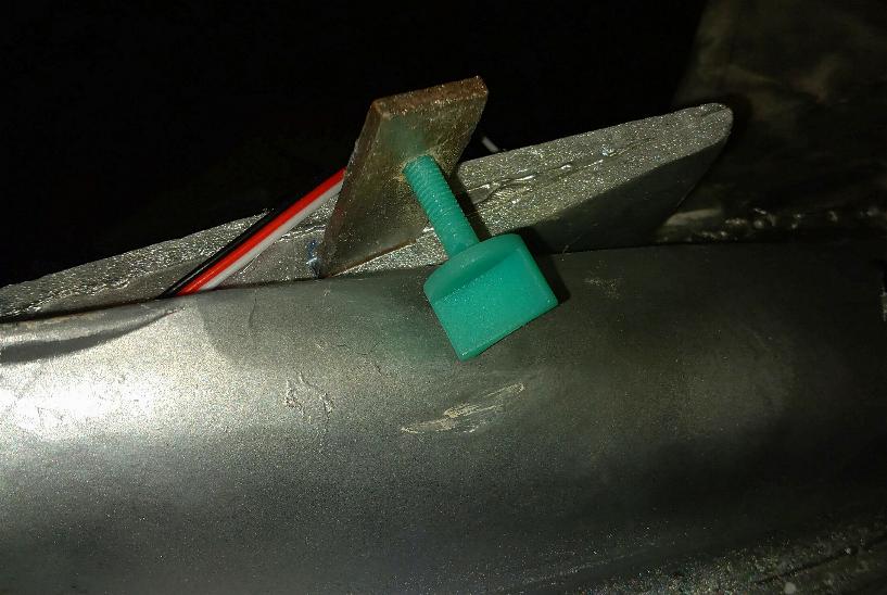
if making a "crib/stand" to keep the fuselage at place vertical aligned, its help for later work)
View attachment 208954
You can even use a ruler to control that the cut for wing at both sides match in height for wing.
If already glued the wing on, set it at a flat place (build surface/floor) and measure on both sides get height similar on both sides.
Some can lay on floor and be flat then.
Wing is measured correct mounted by measure from referencepoints on wing (drawing uses forward line of tip) to straight referncepoints on fuselage front. Eg a former skin connections, or all way to the cowl opening. Always do as far forward as possible.
View attachment 208955
If glued together vertical and horizontal surfaces of tail,set in 90* degrees by a ruler. Then you will have correct alignement of vertical to horizontal tail surfaces. then its just to get it right on the plane..... how to set the tailfin (horizontal) is shown over, and can be used for alignement of the tail vertically/horizontal.
2. I establish a centerline/thrustline all the way of fuselage (at longitudinal axis) . That centerline is set by plane in flat moving in air. Normally already done in 3D views, or plans. On a plane like the drawed here, its quite easy etablish. Center of prop, and to rear of fuselage by a flat line. By that, i know where the line is at rear, and front of fuselage.
View attachment 208953
With the fuselage fully vertical correct aligned, and longitudinal axis aligned by getting the centerline/thrustline flat by putting the model on stand, books, or something....
Measure on plans how high from centerline, or flat "groundline" to the horizontal stab, you know where it should be at the model. Mark it at both sides of fuselage. (if should be flat ( 0 degree) incident) opening/adjust opening to fit the stab.
Measure from underside of stab to groundsurface to get correct aligned height on both sides to control.
Adjust to get correct!
BY WATERPASS:
use same methode as by a triangle ruler to get correct alignement vertical of stab. Methode for getting vertical fin straight by uing nethode at top with the waterpass at same distance from tailfin at bottom and top.
Horizontal alignement for flat 0 degree incident is found by using the waterpass along the side in the wanted height of horizontal stab tailfins following along side at rear when fuselage is set flat at longitudinal axis on centerline/thrustline (as in air) .
View attachment 208960
INCIDENT:
angle on wing/horizontal tailsurfaces you can set by measure with rulers on front and rear of the wing/stab surface, when fuselage is set flat at longitudinal axis on centerline/thrustline (as in air) .
Turned eg fuselage upside down if have a flat bottom of wing, still set flat at longitudinal axis on centerline/thrustline (as in air) .... you can use a angle finder to adjust the incidents correctly by placing flat on wing/stab/tailfin -surfaces wanted to align.
Every angle of a surface (wing, horizontal/vertical fin) can be found by the anglefinder as long the fuselage is set in holder straight.
You can get anglefinders as the one pictured, or digital.. and even anglefinder apps for your mobilphone.
View attachment 208961
All types of measurements are by using reference points (eg at centerlines) and fuselage set correct vertical/horizontal
Every such surfaces written about here, can be adjusted a little before glue is set by holdning it at right angle till dries..
If testfit, and set correct at first, it will not be needed extrawork after.

") ) , before it meet the flat uniform rear to the end of the canopy. 3 parts, same bottle !!
) , before it meet the flat uniform rear to the end of the canopy. 3 parts, same bottle !!