L Edge
Master member
Went to a club meeting and was presented a damaged (6 time thrown) F-16 that was in bad shape. Owner was disgusted and gave it to me for not having any luck in getting it in the air at all. Didn't want anything to do with it and knew I have been using TV for a number of years, so he suggested it would be nice if I could get it to fly. He didn't even want the EDF unit back!!
It weighed 2 lbs and has a 32" wingspan and is 45" long with a 4s 5 blader 70 mm. Boy, was the foam in pieces.
Here is the results.
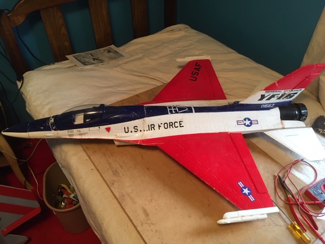
The nose was broken in 3 places. Wondered why?
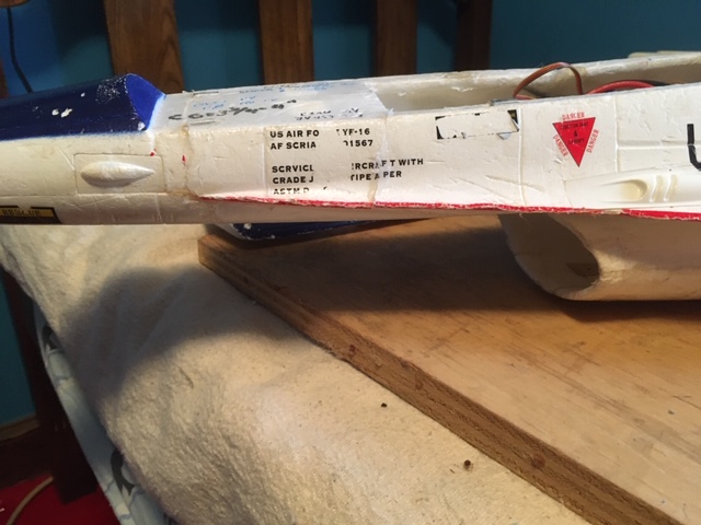
1) The battery had to be shoved all the way forward and just had foam to support it under the long cantilever, where it broke due to the weight and downward force upon a bad crunch with the ground. Solved the foam beakage problem by taking a fine fiberglass thread and epoxy and lined inside from part of the battery to end of canopy.
2) The battery being way up in the front has no cooling!!!! Put a few holes in the nose to provide flow. My test battery was quite warm in vert test.
3) ESC is located in mid upper fuse and continues on to join inlet EDF. Orginally, had no flow to cool it, now holes in nose will provide some flow. ESC should always be available to inlet duct to cool excessive heat.
4) full elevators
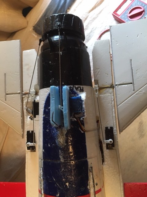
Elevators were in bad shape having an "L" shape rod with short bushing to hold it on. Still, controls are sloppy after epoxy was cured. Really, nothing I could do.
5) Poor design when they left the control surfaces for the TV (elevator and rudder) nozzle on the bottom and protected it with 2 vert fins of foam that the pilot ripped off each time. I used 2 pieces of foam around the servo with a wire loop epoxy into the fuse.
6) Rudder was hot glued back together and all hinges had extra glue added to hold in place for all 3 surface controls.
7) Put it all together and did a vertical hold. Plane was out of control with TV. Jumped all around!!! After inspecting, found that the pin that holds the gimbal ball in it's appropiate axis was sheared, so when you applied say pitch, the ball joint not only moved in that axis, but the yaw axis as well. Problem solved!!!
To solve problem, drilled a small hole thru other gimbal housing, and mounted a "L" shape pin in the groove so it travels in only one axis. Now,
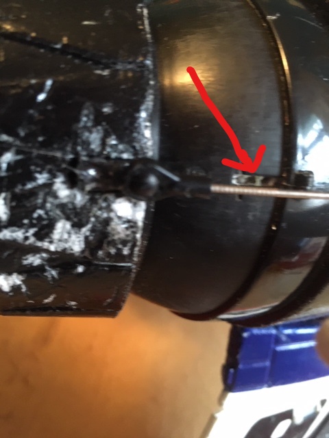
Pin rides in groove below arrow.
8) Did a test that now gives me added info about EDF's. EDF fan is located 17.2 inches from inlet!!! and 10" from end of TV nozzle.
Did not like that, longest I ever used was 8".
Conducted test:
Charged battery to max voltage so both test (before,after)had identical voltage including viewing each of the 4 cells on charger. Then held plane vert so it will hover. It read 64% of throttle to actual quick hand's off model(yeah, it started to rotate).
Now I added CHEATER HOLES (at a 45 degree angle) on the bottom and charged to identical voltage. It now hovered at 57% and you could feel the air being sucked in. Now what the actual value is, don't know, but it should be an improvement in the static and dynamic flow especially if your are doing high alfas. Inlet is about the same as the dia of the 70 mm fan. So long lengths are a no, no.
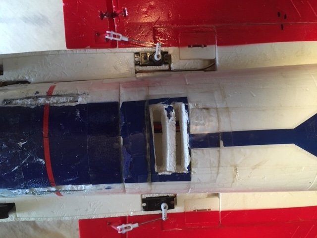
Need to order a matching battery 2200 14.8V and then I am ready to try this wounded puppy and see what happens. These are some of the problems associated of flying EDF's.
Will do a video when weather co-operates.
It weighed 2 lbs and has a 32" wingspan and is 45" long with a 4s 5 blader 70 mm. Boy, was the foam in pieces.
Here is the results.

The nose was broken in 3 places. Wondered why?

1) The battery had to be shoved all the way forward and just had foam to support it under the long cantilever, where it broke due to the weight and downward force upon a bad crunch with the ground. Solved the foam beakage problem by taking a fine fiberglass thread and epoxy and lined inside from part of the battery to end of canopy.
2) The battery being way up in the front has no cooling!!!! Put a few holes in the nose to provide flow. My test battery was quite warm in vert test.
3) ESC is located in mid upper fuse and continues on to join inlet EDF. Orginally, had no flow to cool it, now holes in nose will provide some flow. ESC should always be available to inlet duct to cool excessive heat.
4) full elevators

Elevators were in bad shape having an "L" shape rod with short bushing to hold it on. Still, controls are sloppy after epoxy was cured. Really, nothing I could do.
5) Poor design when they left the control surfaces for the TV (elevator and rudder) nozzle on the bottom and protected it with 2 vert fins of foam that the pilot ripped off each time. I used 2 pieces of foam around the servo with a wire loop epoxy into the fuse.
6) Rudder was hot glued back together and all hinges had extra glue added to hold in place for all 3 surface controls.
7) Put it all together and did a vertical hold. Plane was out of control with TV. Jumped all around!!! After inspecting, found that the pin that holds the gimbal ball in it's appropiate axis was sheared, so when you applied say pitch, the ball joint not only moved in that axis, but the yaw axis as well. Problem solved!!!
To solve problem, drilled a small hole thru other gimbal housing, and mounted a "L" shape pin in the groove so it travels in only one axis. Now,

Pin rides in groove below arrow.
8) Did a test that now gives me added info about EDF's. EDF fan is located 17.2 inches from inlet!!! and 10" from end of TV nozzle.
Did not like that, longest I ever used was 8".
Conducted test:
Charged battery to max voltage so both test (before,after)had identical voltage including viewing each of the 4 cells on charger. Then held plane vert so it will hover. It read 64% of throttle to actual quick hand's off model(yeah, it started to rotate).
Now I added CHEATER HOLES (at a 45 degree angle) on the bottom and charged to identical voltage. It now hovered at 57% and you could feel the air being sucked in. Now what the actual value is, don't know, but it should be an improvement in the static and dynamic flow especially if your are doing high alfas. Inlet is about the same as the dia of the 70 mm fan. So long lengths are a no, no.

Need to order a matching battery 2200 14.8V and then I am ready to try this wounded puppy and see what happens. These are some of the problems associated of flying EDF's.
Will do a video when weather co-operates.
