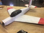
Low-wing Python scratchbuild

Should I work on a set of plans?

  • Yes

    Votes: 5 50.0%
  • No

    Votes: 0 0.0%
  • Yes I would build one

    Votes: 5 50.0%

  • Total voters
    10

Pigfarm1403

Builder
IMG_6408.JPG
-Inspiration
So after finally sorting through all of my stuff from flitefest ohio I was inspired by the clean workspace and organized parts to design my first plane. I have a couple of year of building and I have done a variety of giant builds but I would hardly call those "designs". Some of you might have heard or even seen the hobbyzone v900. The v900 is an extremely fast (120mph) propdriven rc plane that I first encountered at a combat at FFO, when it split my plane in half, since then my interest in faster planes has grown. A month back I bought the flyzone l39 which can hit speeds upwards of 90mph but I would still like to break the 100mph barrier, and so it begins.....

-Overview
After about 8hrs of work I created a durable speed platform I call the "low-wing python". I does not hit near 100mph at this point because it is only the first version of the series I plan on making. I would say confidently that at its current state it can beat any ft plane in speed contest with a power pack c. Key features give it this speed which include the heavily swept back and short wing, no under-chamfered wingtips, and less boxier pieces made out of lowes foamboard, particularly the wingtips and engine cowling. The plane uses a C-pack motor but I am more than likely going to need to upgrade the motor in order to reach 100mph on later versions.

-Electronics/power system
Motor: powerpack c
ESC: 30amp esc
Prop: 10x4.5
Batttery: 3s 1600mah/ 4s which is bad but its fun :^)
Servo: stardard 9g servos
Tx/RX: Flysky fsai6x

-Build


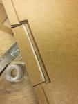
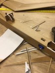
Wing: Unfortunately I forgot to take pictures of the interior of the wing but it is pretty basic. i have two layers of foamboard as formers for the wing and three wooden spars, two for the wingtips and one for the wing joint. For the ailerons I did something a little different and cut out a small area for the ailerons instead of extending the trailing edge. The servos for the ailerons are covered by a layer of water resistant paper from excess foam and the servo wires lead to the fuselage on the exterior of the wing, something I will change in another version.
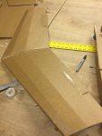
IMG_6383.JPG IMG_6384.JPG

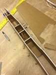
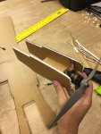
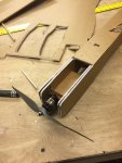
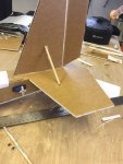
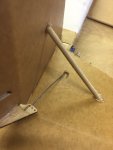
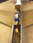
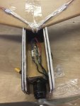
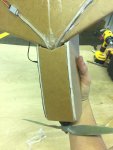
Body: I wanted to have a very sturdy body because I knew I was going to crash this plane and I wanted it to be a durable platform for speed tests. So for the tail of the plane I put in a couple of square formers to help the tail keep its shape after a crash and it worked very well. Another thing I did to make the frame sturdy is I doubled up the nose section so it wouldn't bend side to side if it got worn out. Unfortunately this plane isn't swappable but I am okay with that. One thing I also wanted to do is have a very easy to access area for my electronics so I made the canopy removable and I can store my receiver and battery in the same spot without having to take much of anything apart. The tail controls are very basic and in the second version I plane on moving the elevator servo inside the fuselage and repositioning the rudder servo so I don't have to run the control rod through the elevator.
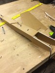
IMG_6382.JPG IMG_6381.JPG IMG_6389.JPG IMG_6386.JPG IMG_6387.JPG IMG_6394.JPG IMG_6397.JPG IMG_6401.JPG IMG_6402.JPG IMG_6403.JPG

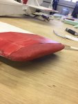
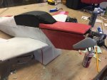
Aesthetics: I went with a simple paint scheme, red, white, and black, and I made more detailed pieces with Lowes 1inch foam-board that i trimmed down and sanded
IMG_6408.JPG IMG_6409.JPG IMG_6410.JPG


-Changes in v2
Body: I am pretty happy with the body and the only change I plan on making is rearranging the servo locations

Wing: In this build i knew my wing wouldn't be the fastest I just wanted to get it in the air, so this is where the next plane will get some more speed. Currently the wing is 12mm which which doesn't sound like much but for a fast place that really thick. This next wing will have a thickness of 9mm to make it sleeker. i also plan on bringing the wingtips out to a point like in the NN Mig 3.


I am VERY happy with the way that this build went and I will definetly build newer faster version and hopefully I will eventually break 100mph with this platform. If enough people ask me to I will work on a set of digital plans but I would need some assistance with reverse engineering the plane. Keep an eye out on this thread because there is more to come and any input would be grealty apreciated. Thanks!
 

Attachments

  • IMG_6404.JPG
    IMG_6404.JPG
    847.5 KB · Views: 0
  • IMG_6399.JPG
    IMG_6399.JPG
    647.8 KB · Views: 0
  • IMG_6407.JPG
    IMG_6407.JPG
    1.4 MB · Views: 0
Last edited:

Pigfarm1403

Builder
Last night I started construction of the new sleeker wing. Tell me if this sounds right, to reduce drag I decreased thickness and in turn the wing chord is longer. Will this even out? I don't necessarily need the same amount of lift as before but will this create a faster wing?
 

Ketchup

4s mini mustang
I think this will create a faster wing, but that is not the only thing that it does, it also makes it easier to flare on landing because of the surface area.
 

Hai-Lee

Old and Bold RC PILOT
Last night I started construction of the new sleeker wing. Tell me if this sounds right, to reduce drag I decreased thickness and in turn the wing chord is longer. Will this even out? I don't necessarily need the same amount of lift as before but will this create a faster wing?
Decreasing the wing thickness will decrease the drag but only very marginally, as Increasing the cord will actually maintain most of the drag. The airflow over any surface has a boundary layer or surface drag and so a larger, or the same surface area will not decrease the drag. The wing Leading edge should be more pointed or sharp as a blunt LE pushes a mass of air in front of it, (Drag). The square wing to fuselage joint angle will provide an increased drag area and so a fillet to round out the joint angle and reduce the surface area will help reduce drag.

Clipped wings reduce drag markedly but also reduce lift, increase take off and landing speeds. To make clipped wings more efficient, (generate more lift than otherwise expected you could consider the use of turbulence generators or fences).

Rounded wing tips are not ideal for high speed flight and you could consider winglets at the tips to reduce the drag and reduce tip vortices at high speed. If possible a symmetrical airfoil will allow wing generated turbulence to be reduced markedly and allow for higher speed runs especially after a gravity assisted approach.

Tail LEs could or should be rounded or even sharpened. You could shape a strip of balsa and fit it to the LE of the tail surfaces. Trailing edges MUST remain rather blunt or control surface flutter could be a problem.

Whilst surface area should be minimised it can be less draggy to lengthen a fuselage and fit smaller tail surfaces to reduce drag even further.

To reduce drag you need to look at where drag is a problem. A square fuselage has a greater surface area than a circular fuselage of the same cross-sectional area. A large spinner could help overcome the blunt nose high pressure area behind the propeller.

As the planes speed capability rises consideration should be given to the use of a smaller diameter and higher pitch propeller as well. The large diameter chews up motor power and the greater pitch means to travel further per motor revolution, (once up to speed that is).

Whilst normally weight is considered as an enemy, you will need a very strong and rigid wing structure and besides using a gravity assist, (a shallow dive), to gain speed prior to a high speed run a little extra weight can be of great value.

Due to the high speeds normally required for a truly high speed RC model especially at take off you could forgo the hand launch and consider a high power bungee launch instead. Would be safer!!

Just a few things for you to consider!

Have fun!
 

Pigfarm1403

Builder
-Plans for V 2.0

Fuse: Lengthen fuse and create smaller tail controls, form a rounded top piece out of Lowes 1inch thick foamboard, add a prop spinner, 3d print a fillet joint for the wing joint

Wing: thinner wing and smaller chord, 3d printed winglets, simple wing fences made out of dtfb
 

Pigfarm1403

Builder
Decreasing the wing thickness will decrease the drag but only very marginally, as Increasing the cord will actually maintain most of the drag. The airflow over any surface has a boundary layer or surface drag and so a larger, or the same surface area will not decrease the drag. The wing Leading edge should be more pointed or sharp as a blunt LE pushes a mass of air in front of it, (Drag). The square wing to fuselage joint angle will provide an increased drag area and so a fillet to round out the joint angle and reduce the surface area will help reduce drag.

Clipped wings reduce drag markedly but also reduce lift, increase take off and landing speeds. To make clipped wings more efficient, (generate more lift than otherwise expected you could consider the use of turbulence generators or fences).

Rounded wing tips are not ideal for high speed flight and you could consider winglets at the tips to reduce the drag and reduce tip vortices at high speed. If possible a symmetrical airfoil will allow wing generated turbulence to be reduced markedly and allow for higher speed runs especially after a gravity assisted approach.

Tail LEs could or should be rounded or even sharpened. You could shape a strip of balsa and fit it to the LE of the tail surfaces. Trailing edges MUST remain rather blunt or control surface flutter could be a problem.

Whilst surface area should be minimised it can be less draggy to lengthen a fuselage and fit smaller tail surfaces to reduce drag even further.

To reduce drag you need to look at where drag is a problem. A square fuselage has a greater surface area than a circular fuselage of the same cross-sectional area. A large spinner could help overcome the blunt nose high pressure area behind the propeller.

As the planes speed capability rises consideration should be given to the use of a smaller diameter and higher pitch propeller as well. The large diameter chews up motor power and the greater pitch means to travel further per motor revolution, (once up to speed that is).

Whilst normally weight is considered as an enemy, you will need a very strong and rigid wing structure and besides using a gravity assist, (a shallow dive), to gain speed prior to a high speed run a little extra weight can be of great value.

Due to the high speeds normally required for a truly high speed RC model especially at take off you could forgo the hand launch and consider a high power bungee launch instead. Would be safer!!

Just a few things for you to consider!

Have fun!
Would the 3d printed winglets used on the FT edge work? They are kind of small but idk. BTW thankyou so
 
Last edited:

Hai-Lee

Old and Bold RC PILOT
Would the 3d printed winglets used on the FT edge work? They are kind of small but idk. BTW thankyou so
As we really need to be aware of the LEs of the winglets and the fences they are best kept as thin and rigid as possible so the standard DTFB might add more drag than benefit. Simplest material I can consider is either 1mm ply, (with LE sharpened or shirt box plastic. 3D printed could work but again if sharpened and sanded to give a very smooth finish.

As to the winglet design it is open to your own preference but keep the vertical size to moderate dimensions.

When lengthening the fuselage and decreasing the tail surface areas do so in moderate steps as the control moment is increased which can make the control responses a little slow. This is not a problem, and most likely beneficial, at high speed but can make landings a little more exciting.

do your improvements one at a time if possible and whilst you may see only little speed gains with each step it will allow you to backpedal if a change causes you either to lose speed or introduce stability issues.

Recommend that you consider a clipped set of wings, possibly with winglets, as your first step! The span reduction could be in the order of 5 to 10% and then test the handing, and landing, differences.

have fun!
 

Pigfarm1403

Builder
As we really need to be aware of the LEs of the winglets and the fences they are best kept as thin and rigid as possible so the standard DTFB might add more drag than benefit. Simplest material I can consider is either 1mm ply, (with LE sharpened or shirt box plastic. 3D printed could work but again if sharpened and sanded to give a very smooth finish.

As to the winglet design it is open to your own preference but keep the vertical size to moderate dimensions.

When lengthening the fuselage and decreasing the tail surface areas do so in moderate steps as the control moment is increased which can make the control responses a little slow. This is not a problem, and most likely beneficial, at high speed but can make landings a little more exciting.

do your improvements one at a time if possible and whilst you may see only little speed gains with each step it will allow you to backpedal if a change causes you either to lose speed or introduce stability issues.

Recommend that you consider a clipped set of wings, possibly with winglets, as your first step! The span reduction could be in the order of 5 to 10% and then test the handing, and landing, differences.

have fun!
Thanks for the advice! I now have a better idea on what the next version is going to be like.
 

Hai-Lee

Old and Bold RC PILOT
Just a heads up! I found this post which could assist with the LE drag issues of the tail feathers! I have not tried it as I use 3mm FB with light balsa LEs where I need to clean up the airflow!

Have fun!
 

Pigfarm1403

Builder
So for this project I am going to be stopping while I am ahead and pursuing digital design project. I have had a better experience with designing and flying planes of my own than build ft planes recently. I want to make my designs more professional and digital and because don't already have a set of digital plans for this one and I don't have time to reverse engineer it I am going to be stopping with this one for now.
 

DamoRC

Elite member
Mentor
So for this project I am going to be stopping while I am ahead and pursuing digital design project. I have had a better experience with designing and flying planes of my own than build ft planes recently. I want to make my designs more professional and digital and because don't already have a set of digital plans for this one and I don't have time to reverse engineer it I am going to be stopping with this one for now.

Bummer - I was looking forward to seeing the 100MPH. Will you be coming back to this one?

DamoRC