Mighty Mini Gloster Gladiator Mk II - Swappable - WWII Biplane Fighter

localfiend

I like 3D printers...
Mentor
Started drawing one of these up last night:


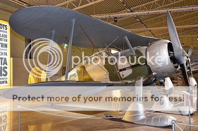
I need electronics and some odds and ends to finish the Bf 109, so it was either get extra work done in the evening or have some fun. So far, I've done two Axis powers War Birds to balance out the Mighty Mini P-51 and Corsair. I think that the Mighty Mini lineup was about due for a biplane fighter. There's just something about biplanes, and the Gloster Gladiator is a beautiful plane.

It's also got a rather interesting history. It was the last biplane fielded by the RAF, and the first fighter to have an enclosed cockpit. It was put into the field just as monoplanes were starting to dominate, and as such, it went to export very quickly. The number of countries that fielded the Gladiator was kinda crazy. The first recorded kill in WWII from a Gladiator, was a US pilot in China who shot down a Mitsubishi A5M.

If I remember correctly, there were a couple squadrons involved in the Battle of Britain, where they were way overmatched. In many of the other theatres, they held their own, or dominated the skies. So many different countries ended up with them, that several ended up on the Axis side, and I believe even the Russians ended up with one.

Here's one outfitted for snow:


So, on to the plans:


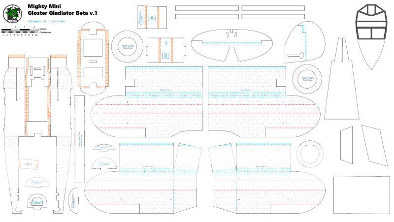
Drawn up with a 24.25" Wingspan, and should be compatible with the F power pack. It will use the standard mighty mini power pod. This isn't really out of line for size. For instance, the real life Bf 109 has a wingspan of 33 feet, and the Gladiator has a wingspan of 32'.

I didn't realize it at the time, but this is the same wingspan as the baby blender. However, with the more refined build techniques, this plane will be far, far, lighter. I'm also going for a thin semi-symmetrical airfoil. This in combination with the rounded wing tips should induce far less drag. The under camber on the tips may add some of that drag back, but I believe it will do a lot to enhance stability.

The fuselage design is something new I'm testing out. Lots of paper has been removed from many parts, including the fuse. For the tail section, I plan to only include as much foam board as necessary for strength. The rest of the skin of the plane will be poster board. Should be just as easy to assemble as any other FT style plane, it will just have the added benefit of lightness and a more accurate rounded fuse. I'm hoping for a bare airframe weight increase of only 25% (it may be less) from the current monoplane mighty mini warbirds. All while doubling the wing area.

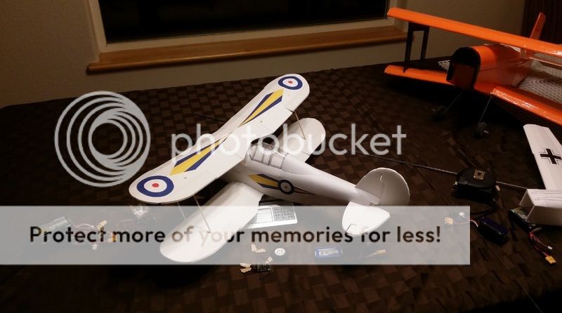
Of course, it will have a hatch to hide the batteries in, and will be getting the full clear canopy treatment. I'm also testing out a better method of creating a round cowl with a smooth rounded transition in the front. Got some goodies from the minwax isle to play with. I'm hoping that a very smooth cowl can be created with very little work.

If all goes well, this one should be slow enough, and agile enough to actually fly indoors.


********************************************************************************

Latest beta plans:

Mighty Mini Gloster Gladiator Beta v.4 Tiled
Mighty Mini Gloster Gladiator Beta v.4 Full


Last edited:

localfiend

I like 3D printers...
Mentor
Like every other plane you've designed, I'll be following this one closely

They do seem to be multiplying. It's starting to feel like I should be investing in a giant bug zapper in case they turn against me. Actually, that might be an entertaining FT episode. :D


OH! OH! OH!


Biplane...

Thought you might like this one. You and I think alike, anything with two wings is exciting.


After dinner this evening I started finishing up the plans for the prototype. Combined the bottom wing halves into one section, moved a few things around, and did the match to get a CG ballpark figure. If I'm actually getting better at this, I'll have less to change on the first build. We'll see how it goes.

Here's what I'm going to build the first one with for anyone that's interested:

Mighty Mini Gloster Gladiator Beta v.1 Tiled
 

localfiend

I like 3D printers...
Mentor
Anybody know much about wing aerodynamics?

Just built half of one wing wing, and it came out as planned, I'm just wondering if I should extend the bottom area all the way back to the trailing edge. The "flaps" that are left in place with a short under wing really seem to help on big planes, but I had trouble with a micro spitfire design (18" wingspan) where I did something similar. If no one has tried a wing both ways, guess I'll just see what happens.

Yeah, my leading edge bevels are ugly. I have one good knife left and don't want to use it yet. :black_eyed: The trailing edge bevels were much smoother even with a rough blade. I cut those after removing the paper, makes it much easier.


Here's the good news. Even if I add more foam to the wing, it'll still be super light.


52 grams for just the wings isn't bad at all, ok, maybe 53-54 counting some hot glue and tape.
 

localfiend

I like 3D printers...
Mentor
Hot glue and tape aren't all that heavy:


What's heavy are the gigantic y connectors that come with the F power pack. They're at least 3 sizes too big, meant for much larger servos. Even after I cut one down, cause they're also super long, it weighs more than a 5g servo:


Bottom wing assembly:


So, 66 grams. If you subtract 16 grams for the electronics and wires it comes out to 50. Not bad. The bottom wing is slightly lighter than the top.
 
I'm going to follow this closely, need a mighty mini to play with. I have built a 50% Ft spit with 2.2mm foamboard that's 54cm from tip to tip. So it should be perfect material for the mini.

and on the heroics of the gladiator: One of the best machinima , it's old but oh so good
 
Last edited:

AircPirateNinsei

airc-pirates.com
A Biplane - this is awesome! Thanks a lot localfiend!

I propose the Heinkel He-51 as a suitable opponent.

2_24.jpg
 
Last edited:

localfiend

I like 3D printers...
Mentor
I'm going to follow this closely, need a mighty mini to play with. I have built a 50% Ft spit with 2.2mm foamboard that's 54cm from tip to tip. So it should be perfect material for the mini.

and on the heroics of the gladiator: One of the best machinima , it's old but oh so good

Thank's for posting this up. I'll have to watch it later this evening when I have time. I remember hearing this story. Malta was in a very bad spot when the Italians decided to join Hitler.

I've been eyeballing the hobbyking 3mm foam board. Been thinking about making a version of the plans for some of my other warbirds for it. We'll see. I keep creating too many projects. :D


A Biplane - this is awesome! Thanks a lot localfiend!

I propose the Heinkel He-51 as a suitable opponent.

2_24.jpg

No problem, this is one I really wanted to do. As for an opponent, I hadn't thought about making another one, but it does make sense. Maybe I'll start a thread with a poll after the Gladiator is finished and see what those who are interested want most. There are quite a few good candidates.
 

Centus

Member
Anybody know much about wing aerodynamics?

Just built half of one wing wing, and it came out as planned, I'm just wondering if I should extend the bottom area all the way back to the trailing edge. The "flaps" that are left in place with a short under wing really seem to help on big planes, but I had trouble with a micro spitfire design (18" wingspan) where I did something similar. If no one has tried a wing both ways, guess I'll just see what happens.

Perhaps I can be of assistance!

I had a similar question when building my latest FT Mustang and seeing your question got me motivated to look into it.
At work I have experience using the 2D airfoil boundary layer code XFOIL, available for free from MIT:
http://web.mit.edu/drela/Public/web/xfoil/

XFOIL allows you to input your own custom airfoil sections and given an estimate of the Reynolds number (I used RE=100k), will produce curves of lift coefficient (CL) and drag coefficient (CD) vs. angle of attack. XFOIL can compute many more predictions, but I'll keep it to lift and drag here.

So here are the two sections I made, FT section1 (bottom plate all the way to the trailing edge) and FT section2 (bottom plate ends around 70% of chord):

FT_sections.jpg

After inputting these geometries into XFOIL, I ran a range of angle of attack. Here are the lift and drag curves for the two sections:

CDvsCL.jpg

CLvsAoA.jpg

CDvsAoA.jpg

Let's have a look at the first set of curves, CL vs. CD for the two airfoil sections. Section2 appears to be the better performer here because it has a lower drag over a large range of lift coefficients (i.e. CL > 0.6), it also has a greater maximum lift coefficient, which will translate into a higher stall speed. However, Section2 has more drag at low lift coefficients (CL < 0.6) and here Section1 has superior performance.

What we have done by reducing the length of the bottom plate is created a section with greater camber and reduced trailing edge thickness. It is like a pseudo-undercambered section.

As with many aspects of aircraft design, the airfoil that is best will depend on your application and what kind of performance you want to accentuate.

For example, because Section2 has a higher maximum CL and lower drag at large CL's it will be able to slow-fly better than the same airplane with Section1. However, because Section2 has higher drag at low CL's, an airplane with that airfoil will likely have a lower top speed than the same airframe with Section1. This is because the CL is low when the airplane is going fast. From some earlier calculations on my Blackwing design (same size wing as the Bloody Wonder) I found that at 12MPH I needed a 2D CL on the wing of 1.1, but at 30MPH I only needed a CL of 0.15.

Finally, if you want good inverted flight characteristics than Section1 is superior. For inverted flight you will need -CL, and we can see that Section2 has much higher drag for the same -CL value.

To sum all this up: Shortening the bottom plate will be best for planes that have higher wing loading and need good stall characteristics (perhaps trainers and STOL), while keeping the full bottom plate will be better for planes that have lower wing loading and need high top speed and good inverted flight characteristics (fighters, aerobatics).

I hope this was helpful and interesting, I had fun looking into it!
 
Last edited:

localfiend

I like 3D printers...
Mentor
Perhaps I can be of assistance!

...snip....

Excellent information! Thanks for looking into it for me, your data seems to have confirmed what I was thinking, its awesome to see the numbers. I'll be downloading that program and playing with it in the future. Looks like an incredibly valuable tool.

Sounds like section 2 is the one I want for this particular application. Slower flight than the other Mighty Minis and good handling is what I'm after. Guess I'll just have to test it out and see how it performs.

I'd like this to fly inverted well, if It ends up not working as well as I would like I can switch to the other style airfoil

Any thoughts on starting angle of attack? If I'm reading the charts correctly, a higher angle of attack is going to generate more lift up until it hits a wall. I would imagine that the higher the angle of attack is, the worse inverted performance is going to be?

Here's how my bottom wing is attached to the fuselage now:

MMGGAngleofAttack.jpg

Seems to be pointed upwards about 3 degrees. When I was attaching the wing, I figured I'd put the flat-ish bottom part level with the fuselage.

ETA: Ignore the paper decking, I'm still working on stuff and the angles there are wrong. :)
 

Centus

Member
You are correct that higher AoA generates more lift until the wing stalls. However, the I don't think the starting AoA matters all that much. What will happen is that the AoA will settle in to where it needs to be to have level flight (assuming that is what the pilot is going for). Meaning, if the AoA is low to start and the lift is less than the weight of the plane, the plane will start to drop. The pilot will nose up a little, increasing AoA until the lift is equivalent to the weight. A large AoA's, the thrust from the propeller will have a vertical component, which will either add or subtract to the lift. That vertical component goes with the sin of the AoA, which is pretty insignificant at small angles. At 3 degrees nose up, ~5% of the propeller thrust will add to the lift from the wings. Anyway, with the bottom part level to the fuselage as you have it, you might end up flying with a slightly nose-down attitude (depending on speed of course, higher speed=lower CL required = less AoA), but I doubt it will be noticeable.
 
Last edited:

localfiend

I like 3D printers...
Mentor
You are correct that higher AoA generates more lift until the wing stalls. However, the I don't think the starting AoA matters all that much. What will happen is that the AoA will settle in to where it needs to be to have level flight (assuming that is what the pilot is going for). Meaning, if the AoA is low to start and the lift is less than the weight of the plane, the plane will start to drop. The pilot will nose up a little, increasing AoA until the lift is equivalent to the weight. A large AoA's, the thrust from the propeller will have a vertical component, which will either add or subtract to the lift. That vertical component goes with the sin of the AoA, which is pretty insignificant at small angles. At 3 degrees nose up, ~5% of the propeller thrust will add to the lift from the wings. Anyway, with the bottom part level to the fuselage as you have it, you might end up flying with a slightly nose-down attitude (depending on speed of course, higher speed=lower CL required = less AoA), but I doubt it will be noticeable.

Ah, ok. That makes sense. I had it in my mind that the horizontal stabilizer on the tail would force the plane to stay level, but it makes sense that lift from the wing would over power that. I imagine that if you get too far off you'll lose efficiency as the wing and the tail fight each other.

I'm probably going to scrap the current fuselage, so I may move the wing and start out level anyway. Still deciding what to do.

A second wing on top makes it a pain to get the hatch on and off. I'm thinking about getting rid of the top hatch all together and coming up with one between the cowl and lower wing. There's a lot of room down there, and it should be easy enough to get a battery in and out. Should also simplify the build and even save a little weight, if I care about weight at this point....


Yeah, that's 225 grams with a 500mah 2s battery. I'm getting 4 minute flight times out of one of those with an F power pack on the Zero. I imagine it would be similar with the biplane, might even be able to add a couple minutes if you drift around. I think a lot of the weight saving come from my test build using paper and not posterboard for decking. Good way to save weight.

Final build may add a few grams (needs canopy added), but it's starting to look like sub 250 grams will be possible. If it actually comes in at 225 grams all built that's a wing loading of 5.71 ozs per square foot and WCL of 4.8. Yeah, it'll fly just fine indoors.
 

AkimboGlueGuns

Biplane Guy
Mentor
Sweet! I'ts looking really good. I might try building one with a slightly different cowl/wing/tail shape to make it look like a Pitts Model 12.
 

dutchmonkey

Well-known member
the only thing in the airfoil sketch i noticed is "section 2" is not really true to FT style wings the bottom plate is usually flat and the top layer extends over the bottom creating a undercamber not sure if that will change the results much but would be inserting to see. kinda like this foil.JPG
Perhaps I can be of assistance!

I had a similar question when building my latest FT Mustang and seeing your question got me motivated to look into it.
At work I have experience using the 2D airfoil boundary layer code XFOIL, available for free from MIT:
http://web.mit.edu/drela/Public/web/xfoil/

XFOIL allows you to input your own custom airfoil sections and given an estimate of the Reynolds number (I used RE=100k), will produce curves of lift coefficient (CL) and drag coefficient (CD) vs. angle of attack. XFOIL can compute many more predictions, but I'll keep it to lift and drag here.

So here are the two sections I made, FT section1 (bottom plate all the way to the trailing edge) and FT section2 (bottom plate ends around 70% of chord):

View attachment 62109

After inputting these geometries into XFOIL, I ran a range of angle of attack. Here are the lift and drag curves for the two sections:

View attachment 62112

View attachment 62111

View attachment 62113

Let's have a look at the first set of curves, CL vs. CD for the two airfoil sections. Section2 appears to be the better performer here because it has a lower drag over a large range of lift coefficients (i.e. CL > 0.6), it also has a greater maximum lift coefficient, which will translate into a higher stall speed. However, Section2 has more drag at low lift coefficients (CL < 0.6) and here Section1 has superior performance.

What we have done by reducing the length of the bottom plate is created a section with greater camber and reduced trailing edge thickness. It is like a pseudo-undercambered section.

As with many aspects of aircraft design, the airfoil that is best will depend on your application and what kind of performance you want to accentuate.

For example, because Section2 has a higher maximum CL and lower drag at large CL's it will be able to slow-fly better than the same airplane with Section1. However, because Section2 has higher drag at low CL's, an airplane with that airfoil will likely have a lower top speed than the same airframe with Section2. This is because the CL is low when the airplane is going fast. From some earlier calculations on my Blackwing design (same size wing as the Bloody Wonder) I found that at 12MPH I needed a 2D CL on the wing of 1.1, but at 30MPH I only needed a CL of 0.15.

Finally, if you want good inverted flight characteristics than Section1 is superior. For inverted flight you will need -CL, and we can see that Section2 has much higher drag for the same -CL value.

To sum all this up: Shortening the bottom plate will be best for planes that have higher wing loading and need good stall characteristics (perhaps trainers and STOL), while keeping the full bottom plate will be better for planes that have lower wing loading and need high top speed and good inverted flight characteristics (fighters, aerobatics).

I hope this was helpful and interesting, I had fun looking into it!
 

Centus

Member
Dutchmonkey: that is a good point. The "section2" that I came up with were based on the pictures that localfiend posted, where he did a really nice job beveling out the back edge of the bottom plate. The section that you show would actually be quite difficult to model in XFOIL, due to the step created by the back edge of the bottom plate. Some of the assumptions that XFOIL is based on don't hold up very well for sharp corners like that. What is often done to treat geometries like the one you posted is to eliminate the step by extending the surface along a streamline, assuming that the flow separates behind the step. This obviously introduces some uncertainty because the separated streamline is not already known. Alternatively we could just round the step off a little bit and see how that goes. The code runs in seconds, so both could be tried.
 

dutchmonkey

Well-known member
Centus: i did not notice that on this mini he tapered his connection point on his other mini's they are not and more like the drawing i posted. would be interesting to see what xfoil says about this foil its kind of like KF airfoil and should act like a under-camber but it should also create more drag then the under-camber airfoil does
 

localfiend

I like 3D printers...
Mentor
Dutchmonkey: that is a good point. The "section2" that I came up with were based on the pictures that localfiend posted, where he did a really nice job beveling out the back edge of the bottom plate. The section that you show would actually be quite difficult to model in XFOIL, due to the step created by the back edge of the bottom plate. Some of the assumptions that XFOIL is based on don't hold up very well for sharp corners like that. What is often done to treat geometries like the one you posted is to eliminate the step by extending the surface along a streamline, assuming that the flow separates behind the step. This obviously introduces some uncertainty because the separated streamline is not already known. Alternatively we could just round the step off a little bit and see how that goes. The code runs in seconds, so both could be tried.

Good discussion guys. I don't think there are any computer models out there that know what to do with a KF step. As far as I'm aware, we know the effect a KF step has, we just don't really know why it does what it does. I think there have been a few theories, but nothing proven yet and no real mathematical models to back it up. If I'm wrong let me know, that would also be great information to play with.

Sweet! I'ts looking really good. I might try building one with a slightly different cowl/wing/tail shape to make it look like a Pitts Model 12.

Yeah, you wouldn't have to change much. Just lengthen the nose by a bit and blend it into the fuse. The fuselage is wide enough that blending the round part won't cause issues with the power pod. All the other fuse lines are pretty much the same.
 

localfiend

I like 3D printers...
Mentor
Parts for the Bf 109 didn't get here like I was hoping they would, so it's back to the Gladiator. Done a bunch of tweaking to the plans and I'm going to be building a new fuselage and upper wing. The new fuse will be without the top hatch, with parts for a bottom hatch design. I'm building a new top wing as I decided I should have kept the flat middle portion of the wing. If you go with standard dihedral it obstructs the pilots view. If there was a pilot. ;) Mostly it just doesn't look right.

Here's what I'll be building off of:


Mighty Mini Gloster Gladiator Beta v.2 Tiled