Snarls

Gravity Tester
Mentor
Its time for version 2 of the scratch build ROV. The last design worked on land, but not in the water...which is unfortunate for a vehicle designed to work under water. Despite this fail with version 1, there was a lot that I learned about ROV design that I can apply to version 2. The main goals are the same; build an underwater vehicle capable of being controlled down to 50 feet of depth, with a camera feed to examine what's below.

Here are some of the major lessons I learned through the first version:
-Making watertight containers is difficult.
-The previous design had way too much buoyancy and the electronics I am using do not require a lot of room.
-If the thrust vector is not in line with the crafts CG, the ROV will not dive straight down or propel horizontally.
-Having a place to add ballast weight is important.
-Being able to adjust the thruster position is important.
-A spot to mount attachments such as an grabber arm in the future would be nice.
-It is best to keep the number of points of entry into the sealed compartment at a minimum
-It is probably more useful to have the lights and FPV camera pointed slightly downward than straight ahead.
-The electronics were hard to work on after installing in the body.

Based on these lessons, my plan for version 2 of the ROV is to start with getting a watertight container. The 3D printed body of the last design took a lot of time and work to build, and it was very difficult to make watertight. Instead of 3D printing a custom body, I plan on using a PVC pipe with one end permanently capped off, and the other with a removable cap. Hardware stores sell PVC pipes, caps, and removable ends that are designed to be watertight. It will also be much easier to assemble. Additionally, these PVC pipes are rated for certain pressures, so I will be able to tell if the construction will withstand the pressures at 50 ft of depth. I am also going for more of a traditional ROV design, with a smaller electronic container and a large exoskeleton of sorts, where equipment can be attached. The electronics will be mounted on a sled, which can be removed from the PVC tube for easy servicing. The position of the horizontal thrusters will also be adjustable vertically, to align the thrust vector with the CG.
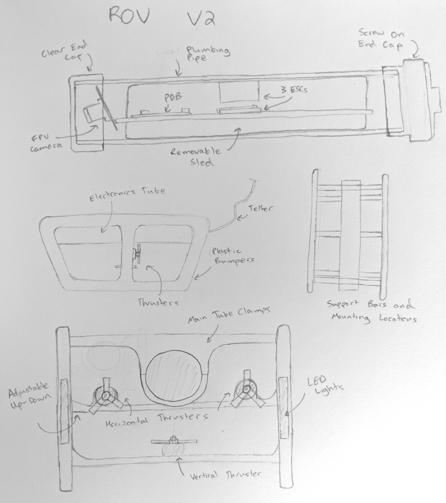
V2Planning.jpg


CAD designs and renderings to come shortly!
 

Hai-Lee

Old and Bold RC PILOT
Just a few thoughts which you can ignore if you wish but have you thought of pressurizing the craft? Also there is a simple leak suppression device for small items and that is to grab a powder that releases Co2 when it comes into contact with water. This gas would increase internal pressure and maybe even provide a gas leak which will indicate the issues and the leaks when under the water, (a bubble stream).

Filling the internals with transformer oil or the like would protect the electrics and also stop water leaks as liquids are not compressible as you are aware.

An open frame design with a small sealed electronics enclosure could assist with the whole ballast/buoyancy issue that you encountered in the previous version.

Have fun!
 

Snarls

Gravity Tester
Mentor
Thanks guys, I am really excited to get something working and finally explore my local lakes and ponds. Actually one reason to get this working asap is to rescue one of my friends quads which we are pretty sure lies at the bottom of a murky pond. I'll take my time to get it right this time though.

I'll definitely be keeping track of all your opinions and suggestions as this project progresses. Right now the main goal is to get the electronics enclosure assembled so I can bring it to the local lake and drop it down the deepest point (~40 ft) and see if it leaks (nothing inside of course).
 

Snarls

Gravity Tester
Mentor
Here are a couple initial renderings to show what I'm thinking of for the design. All the electronics are stored in a PVC tube, sealed from the water. For size reference, the length of the tube is 1 foot. The front of the tube has an acrylic window for the FPV camera to look out of. In the rear of the tube will be either a screw on cap, or a 'test plug' that I found, which fits in the end and has an o-ring that expands when you tighten the plug. Wires will exit the tube through the white 'ports' you can see towards the rear. These ports are inspired by a method Blue Robotics uses in their systems, in which the wire goes through an epoxy barrier before entering the container. The electronics tube is secured to the rest of the ROV frame using some 3D printed tube clamps.

The side bumpers/rails and bottom 'H' are simple shapes I will cut out of some synthetic wood paneling I have. The horizontal and vertical thrusters will be mounted to these pieces using a clamping technique. Because the motor mounts are attached with clamping force, and not directly bolted on, I will be able to adjust the position of the thrusters to get the optimal thrust angle.

From just a quick calculation of buoyancy on the electronics tube alone, the tube will have to be at least 2 lbs to be neutrally buoyant. The tube and caps already weigh 1 lb, so there is a possibility this build will be negatively buoyant. In that case, I can put foam blocks on the top of the frame to add buoyancy. Foam blocks are commonly seen as the yellow tops on many industrial ROVs, so the idea is not unheard of.

ROVv2Trimetric.png


Side.png


Front.png


Top.png
 

Hai-Lee

Old and Bold RC PILOT
Looks like a promising design. Later you might consider the addition of some LED lighting on a detachable boom in front of the camera and even perhaps a boom, (with a few tines), to carry a rescue line with loop to position over the device to be retrieved.

I will watch this to see how it goes!

have fun!
 

b-29er

Well-known member
A thought on your acrylic, instead of just gluing it to the front, maybe take a cap for that size of PVC and drill a hole in the cap the same diameter as the inside of the pipe, then sandwich the glass between the end of the pipe and the cap. That way you give something for the glass to seat into, and also protect it in the event of an impact.

I notice you arent using batteries on the ROV, which i know probably sounds kind of dumb, but something to consider is your tether. You want a tether that is neutrally buoyant, otherwise what will happen is the tether will pull your craft towards the surface, and not just straight up/down, so you will need to fight the tether the entire time you are down there. A smaller tether also tends to bend easier and let you maneuver a little better, but thats up to you entirely. But you may see the advantages on having unlimited power, which is fine, but you may want to test if your current cable floats/retains air, and if there is a difference with the cable having its sheathing on or off, since thats easy enough to remove.

On your material, unless you're talking about the fake wood thats actually recycled plastic, i'd probably stay away, just because depending on the kind of paneling, MDF will absorb the water like a sponge, and most woods short of like teak will absorb water in some way unless properly treated, affecting buoyancy. If you want to be sure, test it out, take a 1' square of a known thickness and attach fishing weights to it until it sinks. Add more, leave it in water for 24hrs and re-test to see if there is much of a change. 3d printing might actually be fairly viable for the frame, especially if you print the frame pieces on their sides and run the prints with a fairly dense infill and without a top and bottom so no air gets trapped inside. Alternatively home depot stocks might work for the frame, conduit and the like would be very simple, but you could also take a router and cut a frame out of a few layers of clear acrylic screwed together.

Also, one thing to consider when you are doing all this, your pitch. If you are good with your pitch being fixed (aka the ROV doesnt pitch up or down) then you can just use weights. If thats not ok, you may want to figure out something like a pair of connected pneumatic cylinders, one fore, one aft, to give yourself some pitch authority.

One last thing, if you run out of channels on your wii mote and have an RC radio, JR modules output a PPM signal through the pins in the back of the radio, and the code exists to turn PPM to PWM by channel for servos.

Also, considering that this new design appears to be much taller, you may want a better understanding of where your center of mass is. The only reason i say this is because if you mount your motors too high or low, you might wind up with unintended pitching movements. I would try to figure out where your center of mass is both vertically and horizontally, and mount your motors in relation to that (pusher motor shafts at the same height as the center of mass, props inline with cmass, depth motor mounted inline). It looks like you have most of that, and your current frame design will give you a lot of flexibility if you do need to change stuff in the future.

Also, if you want to stay with your v1 design, i would mention a lot of RC submarines use a tube system for their powerplants/radio/ballast instead of an enclosure. If you can retrofit your design to use a pair of PVC pipes mounted next to each other for your enclosures, you may still be able to get that working and just use the PVC pipes to enclose your electronics.

Also also

Actually i may just build one of these myself, looks super fun. Are you planning on using reversible ESCs?
 
Last edited:

Snarls

Gravity Tester
Mentor
@Hai-Lee You're right I forgot to add the LED lights to the CAD model. I'm debating wether to have two arrays, one on each side of the frame, or to have one mounted centrally near the bottom. Or maybe even have one array inside the tube, surrounding the FPV camera, but that may blow out the image. A boom is also a good idea. I have a robotic arm grabber that I was thinking of eventually attaching in the front, but a just a rope and loop, or even a hook, would be a simpler method to implement.

@b-29er Lots of good points you brought up. For now I have just replaced the end of an end-cap with the acrylic, just butted up to the end of the cap and sealed with super glue and silicone. It seems pretty solid, but if it fails I will try your idea. I actually do plan to have a lipo battery inside the ROV, but if weight is an issue I can move the battery to the surface.

The tether buoyancy is a valid concern. I am using a cheap 50 ft Ethernet cable as the tether. I am not sure if it floats or sinks, but I'll find out when I test the electronics tube for leaks. I know OpenROV uses a neutrally buoyant tether with their Trident ROV. I'm not sure how easy it is to make my own, or where to buy one. Eventually I want to upgrade to a serial link between the surface station and the ROV (instead of just sending raw ESC signals), and I can upgrade the tether then.

I'm pretty sure the synthetic wood I have is some plastic material. It is all white and is used for some of the paneling on the exterior of my house. I will see if it absorbs water. If it does I can try sealing it, or find something else to use.

Pitch is not a feature I am too concerned about having right now. We'll see how that changes once I start using the thing. Also good tip about the JR modules. The wii mode is running out of control methods I can use. It does have an accelerometer with which I can do some futuristic motion control though.

I'm not sure where the CG is as of now. I could do some extensive part modelling to calculate it, but instead I have made the position of the thrusters adjustable so that I can dial things in once it is constructed.

I could retrofit the old design, but I actually think building this new one will be faster. Especially since all the electronics and programming has been figured out. I also already put conformal coating on the electronics from trying to salvage the first design. So if the new electronics tube fails there will also be a second line of defense.

Thanks for all the input guys!
 

Snarls

Gravity Tester
Mentor
Made some progress on the electronics tube. I picked up a short section of 2" i.d. PVC pipe, an end-cap, a screw on end cap, and an o-ring based 'test plug.' I would prefer the test plug as a removable method to seal the tube because it is easier to tighten down and then release. I will try that first and see if it leaks, and move on to the screw on cap if it does.

The PVC pipe is rated at 280 psi. Keep in mind that is for internal pressure, whereas I am using the pipe in an application where it receives external pressure. This places the pipe under a compressive stress instead of a tensile stress. A lot of materials are stronger in compression than tension, and according to this source, PVC is just that way. But it's not just the material strength which determines whether the PVC is stronger in compression or tension. The failure mode in internal pressure versus external pressure is different for a PVC pipe. I looked around and found several different equations for the primary failure mode of an unsupported pipe under an external load, the method being collapse/buckling. Some calculations using the equations gave external pressure ratings up to 447 psi, but overall a lot of experimental based charts showed collapse pressures for PVC less than the burst pressures. So there is some disagreement there, but the take away is that under compression, PVC pipe of 2" i.d. can still support at least a couple hundred psi.

A quick calculation of pressure using my intended depth of 50 ft gives the following:

Pressure = density * gravitational acceleration*height
Using a water density of 1.940 slug/ft^3, with 50 ft of height, we get:
eqn.gif

That is just the external pressure. Important to remember is that the inside of the tube will be at atmospheric pressure, which is around 14.7 psi. So the net external pressure on the pipe will only be around 7 psi. That is far below what some sources suggest as the collapse rating for a pipe of this size. So as far as the pipe is concerned (not the end caps), the pressure is no problem.


Back to the build. For the end where the FPV camera is going, I cut the end off the end cap and cut a circular piece of 1/4" acrylic to replace it. I joined the acrylic to the PVC with a generous bead of super glue, and added an additional silicone seal on the inside for good measure. I also cut the PVC pipe to a 1 ft length in accordance to my design.

FrontEndCap.jpg


ElectronicsTubeParts.jpg


I need to have at least 17 wires exiting the electronics tube for everything to work. There are 9 for the ESC to motor connections, 3 signal wires for the ESCs, 12 V, 5V , GND, a signal to trigger the LED mosfet, and the FPV camera signal. Eight wires will come through with the tether. Additional wires for the ESC to motor connections and LEDs will exit the tube through a different point. I did some research on what other ROVs use for wiring interfaces and came across a method used by Blue Robotics. They have the wires pass through a questionably named 'penetrator' which penetrates into the tube and seals with an o-ring. The wire is then epoxied into the penetrator to seal it.

Inspire by this, I create my own 'penetrators' with my 3D printer. Instead of messing with o-rings again, I decided to get have the pieces epoxied to the tube. The wires are epoxied within each penetrator to seal it. The tether only has one 8-wire cable, whereas for the motor outputs I am using two 8-wire cables. For now I only need 9 wires for the motors and 2 for the LEDs, but it will be nice to have the remaining 5 available for future operations like an actuated arm.

WirePorts.jpg


WirePortHoles.jpg


Right now the 'penetrators' are being epoxied to the tube. The next step is to attach both end caps to the tube, and then take it out to the lake for a full depth leak test. I am confident it will hold up.
 

Attachments

  • 1534974767776.png
    1534974767776.png
    2.5 KB · Views: 0

Hai-Lee

Old and Bold RC PILOT
A quick method to check the seals and their function is to cut a second acrylic window and fit a tyre valve stem and valve as well as a pressure gauge. Pressurize it and see if the air escapes over time! If air gets out then water can get in!

As for the pressure handling I believe that you are quite safe at the depths you are considering but the failure mode of a finite length is centrally along its greatest dimension where the pressure can exert greatest leverage. To reduce such weakness a couple of PVC bulkheads or rings can support the centre section and each long span division created to massively improve the load bearing capabilities of the structure.

just my thoughts!

have fun!
 

PsyBorg

Wake up! Time to fly!
Two thoughts I have are look into the water tight connectors they use for the sensors in cars that have rubber seals and locking clips.

They may add expense but it makes repairs as well as add on externals like an arm much easier to work with.

Second consider using some kind of screen type barrier around your motors. If you wrap sea weed or other vegetation up in the motors you may not be able to retrieve your ROV.

Other then that the new design and thought process is going in a better direction then the larger sealed body design I think anyways.

Good luck on the next round of tests.
 

Snarls

Gravity Tester
Mentor
Here are some more pictures of the build. My dad and I took the tube out on the local reservoir last week to test the water tightness of the assembly. We paddled out to the deepest spot in the reservoir which is around 40 ft, but maybe closer to 50 ft as I was running out of cable. I dropped the tube all the way down to the bottom and left it there for at least 10 minutes.

Canoe.jpg


Testing.jpg


After 10 minutes I reeled the tube back in. To my dismay, I noticed some small bubbles coming out of the tube when it got closer to the surface. However, the tube was not full of water, and I could not get it to visibly leak when I emptied it out and dunked it back under. I think there is a small leak where the wiring enters the tube. Some of the hard epoxy chipped off and gives a very slight gap around the wire. I think the solution is to use something flexible to seal around the wires. Something like silicone or Shoe-Goo, maybe even hot glue.

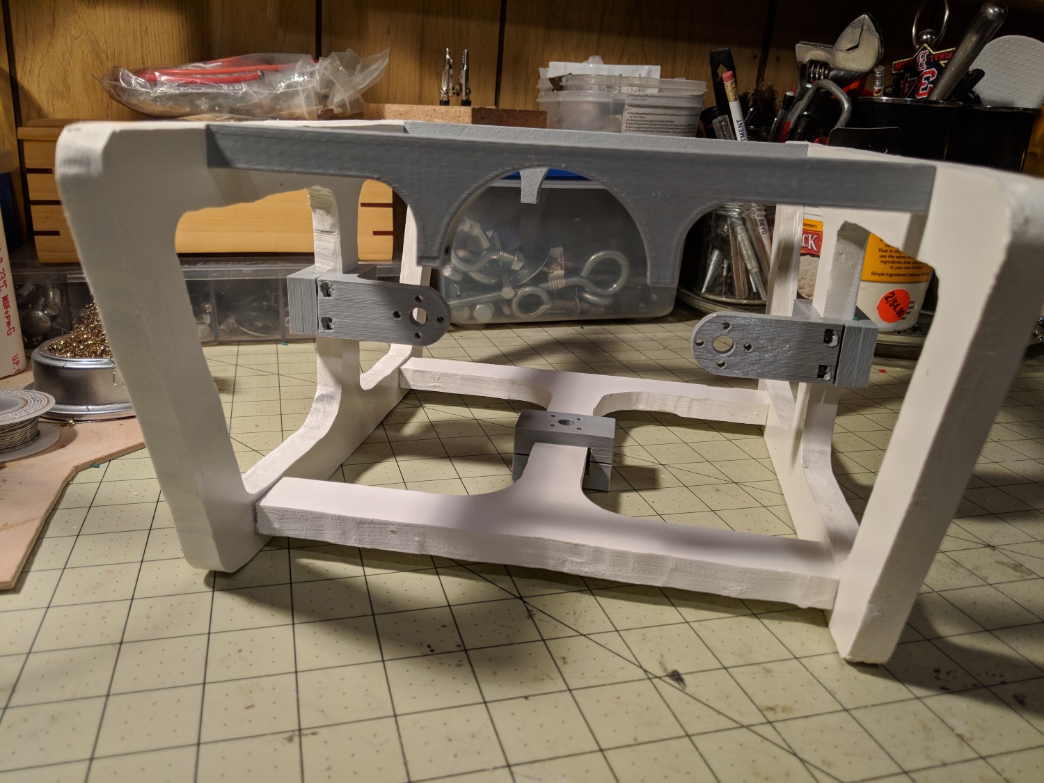
It took about two days to get all the 3D printed parts made. I also spent a day cutting out the other frame pieces from some plastic wood material. They were a real pain to cut. My scroll saw has a dull blade and it kept melting the plastic. As a result, the cut I made would fuse back together I would have a single piece even after cutting! Unfortunately these frame parts aren't quite up to my standard as a result of all the sanding I had to do to fix the melting. I'll use the anyway, but consider getting some acrylic or something lasercut in a future design.

PrintedParts.jpg


CutParts.jpg


Altogether, the frame is looking good. It is larger than version 1 of the ROV, and maybe a bit overkill. I will see what motor positionings are required for good control, and maybe update the frame size from there. The motor mount positions are adjustable by about 1.5 inches in each direction off center. I still don't know if this craft will be overweight or underweight.

Frame1.jpg


Frame2.jpg
 

Hai-Lee

Old and Bold RC PILOT
In my dealings with military grade equipment most of which had to have a waterproof rating there was something that was used to pass signal and power through waterproof bulkheads and they are loosely labelled as feedthroughs. A sample of one type is shown in the following pic;

Solder-Mount-Feedthrough-Capacitor-100V-102.jpg_350x350.jpg


As braided cables bleed water down the insulation especially under pressure the external and internal cables are connected through the water tight exterior via feedthroughs. The ones illustrated can be directly soldered to a mounting plate and the plate secured to the cable entry to the tube. TO reduce the effects of the water upon the signals themselves you could print a cover with your standard cable entry mechanism and fill the cover with something that will not compress and will not effect the signals like a good dielectric vegetable oil. This could be acheived by a simple screw hole which has a screw fitted after the cover void is filled.

Just what I was taught!

Have fun!
 

Snarls

Gravity Tester
Mentor
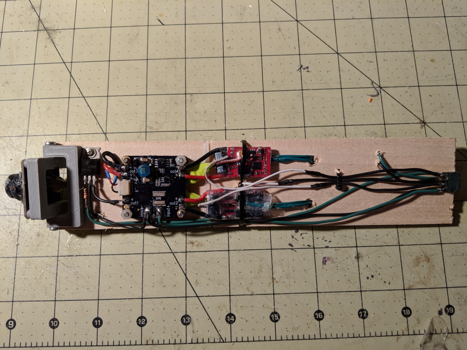
I've been working on the electronics for the past week. It is the exact same components as the first version, so I did not really document the exact wiring. This time, the electronics are mounted on a sled that fits in the PVC tube. In the first version the electronics where just freely floating inside the ROV body. It was really messy, but it was hard to work inside that body, so I couldn't bother with making the wiring neat. This time with sled the electronics are laid out much neater and it is way easier to work on. The wires terminate at female pin headers, which allows the entire sled to be disconnected and removed from the ROV. I also mounted the FPV camera on a simple pivot so that I can adjust the angle for optimal viewing.

ElectronicsSled1.jpg


ElectronicsSled2.jpg


Here the tether and motor wiring is connected to the electronics sled. The sled can be pushed further into the tube so that the end shown can be sealed.

WiringConnectors.jpg


I have also been working on the LED lights. I am using a similar concept to the first ROV, with the LEDs in a little box. The box will be filled with some clear silicone so that the LEDs are protected from the water.

LEDBoxes.jpg


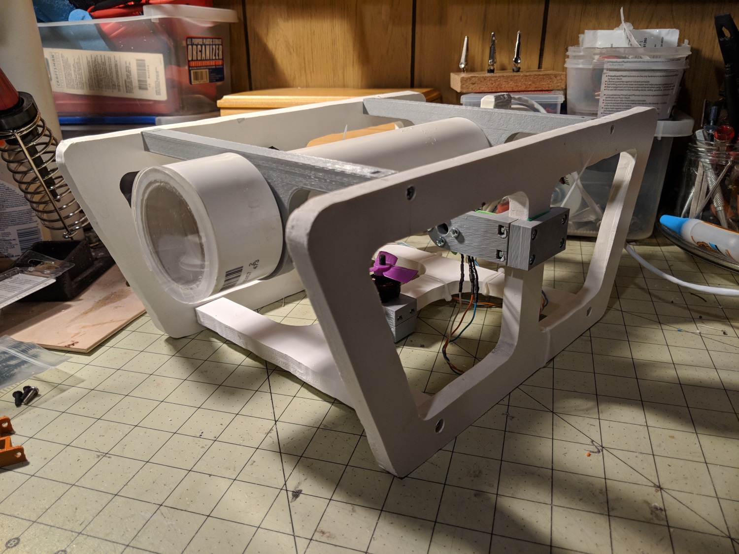
Here is the ROV v2 about 90% assembled. The LED lights still need to be installed, and the wiring needs to be looked over once more to seal any more gaps. I am also going to need to find out if I need to add weight or add foam floats to get this craft neutrally buoyant.

Assembled1.jpg


Assrmbled2.jpg


I did some testing of the electronics and found a strange and concerning problem. If I power the ROV by plugging in a battery on the surface side, the ESCs do not initialize properly. It took me a lot of troubleshooting to find out why they wouldn't initialize. I eventually found that if I plug in a battery on the ROV side, the ESCs work fine. I think there is something with either the length of the tether, or the gauge of wire in the tether, that is killing the i2c communication/freezing my arduino and preventing any operation. I was a bit skeptical of the tether being able to handle the current for the motors with the battery mounted surface side anyway. So it looks like I will have to place the battery inside the electronics tube on the ROV. Luckily this version of the ROV is designed in such a way that the electronics tube can easily be opened to plug in or place a battery. Unfortunately, the only battery that current fits is a 500 mAh 3s, and the ROV will have to be surfaced every time the battery needs to be changed. I will have to see how long I can run the ROV on such a size battery, and make modifications as necessary.
 

Hai-Lee

Old and Bold RC PILOT
You could add an external battery/ballast tray to supply the reserve of power and the connection of the battery/batteries could be under the control of the tether cable so that you can "SINK" the ROV prior to enabling the system, (thereby saving power). Of course the battery tray to electronics pod cables would be of high amperage cable. The sink could be easily achieved by and added weight which is removed via a separate release string/rope.

Just my thoughts!

Have fun!
 

b-29er

Well-known member
You could add an external battery/ballast tray to supply the reserve of power and the connection of the battery/batteries could be under the control of the tether cable so that you can "SINK" the ROV prior to enabling the system, (thereby saving power). Of course the battery tray to electronics pod cables would be of high amperage cable. The sink could be easily achieved by and added weight which is removed via a separate release string/rope.

Just my thoughts!

Have fun!

Another thought, RC submarines are using a piston-based active ballast system, essentially using a syringe driven by a servo or motor system to suck in water, reducing the sub's buoyancy. Such a system could easily be implemented on your ROV if you take a syringe from Tractor Supply and use a servo and some airline tube to draw in/out water to change buoyancy

Also, i am not sure how much infill you used on the 3d printed structure of your sub, but that may be something to consider, as it may start out filled with air and finish up filled with water!
 

Snarls

Gravity Tester
Mentor
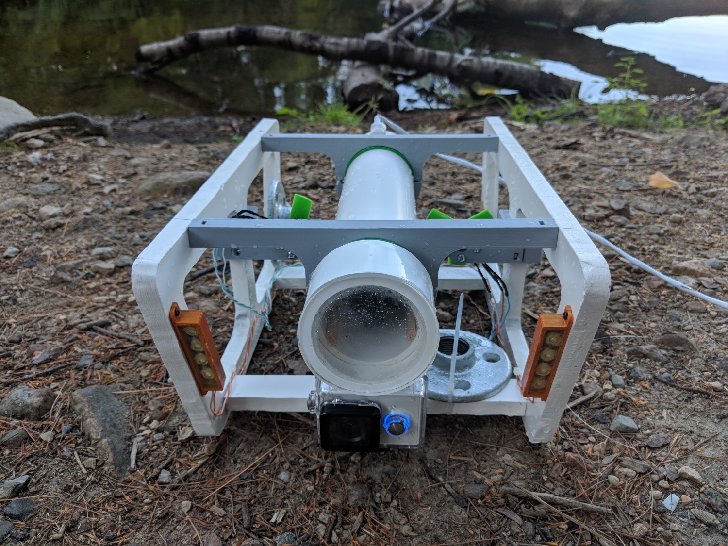
I took the ROV out to the local reservoir for some field testing this afternoon. The results were mostly positive with some small issues. Starting with the bad, the electronics tube still leaks slowly. I'm pretty sure it is leaking at the end cap, which is just a o-ring that expands when you tighten the cap. I have an idea of what I can do as a better replacement, and that is gluing up right now. Luckily the leaking was slow enough that I could get on with testing the ROV powered and moving. Another problem was that the ROV would sit in the water not horizontally, but at an angle, like the sinking Titanic. This, and buoyancy in general, was a major issue with the first ROV, and it has to do with the mass and it's distribution along the craft. To fix it, I moved one of the weights I was using from the back to the front, and that seemed to level things out, although the ROV still had a slight tilt on the roll.

That's right, I had to add weight to make the ROV neutrally buoyant. I kept thinking this build would end up on the heavier side, with me having to add foam to make it neutrally buoyant. I weighed the assembled ROV and found it to be just around 3 lbs. Using the volume of the ROV calculated in Autodesk Inventor (~118 in^3), I calculated the associated weight of water to be around 4.3 lbs. This meant I needed to add 1.3 lbs to the craft to make it neutrally buoyant. Much less than the 5 lbs needed for v1, but still quite a large amount. I made some more calculations, and it turns out the plastic wood I used is less dense than water, contrary to my assumption. The 3D printed parts are likely the same. So pretty much everything but the motors and hd camera has positive buoyancy that needs to be compensated for with added weight.

Unfortunately, my FPV feed was also not working. I was just receiving static on the monitor. When I got back home I did some more testing and found that I need to power the FPV monitor with a separate battery on the surface side. Powering it through the tether from a battery in the ROV was just not working with such thin wires in the tether. With a dedicated monitor battery, the FPV feed works as intended.

Now on to the good news. I was finally able to test the ROV's controls for an extended period of time. Version 1 only lasted a few seconds before water glitched out the system and prevented the motors from moving. Today, I was able to control the craft for at least 5 minutes before pulling the plug myself. I was able to test all the controls; forward, back, left, right, up, and down. I had my left and right reversed, but unlike aircraft, the ROV won't crash if you mix up the controls. Man this thing is controllable. With just a small push on the joystick it glides smoothly at a good pace through the water. I thought turning would be shaky, but it turns like a tank and stops right where you want it, as if it's running a well tuned PID loop (it isn't). Diving and surfacing also work great, with it moving vertically at a good pace. I thought I would need to do some tweaking to my control mixing to get it more accurate, but I think it is good enough to continue using for now.

Water1.jpg


Water2.jpg


Water3.jpg


You can see the weights I used are just heavy metal hardware pieces. That's what I had on hand that would add up to 1.3 lbs. Ideally I would use some flat lead pieces. I am also thinking of having some sort of box mounted on the bottom that I can fill with rocks/sand/scrap to have more control when adjusting the weight.

I did the testing with a 500 mAh 3s Lipo because that is all that fits inside currently. After 5 mins, the battery is about half empty. Not too bad, but I would like to get longer dive times so I can spend my time slowly searching and exploring the depths without worrying about timing out. Fitting a 2200 mAh would be better, and I also have 3 of them to use.

Next step is to stop the remaining leaks, dial in the weight/neutral buoyancy a little more, fit a bigger battery inside, and test the system with the FPV feed.
 

PsyBorg

Wake up! Time to fly!
Vasoline.....

Use the rubber O ring but coat the threads with vasoline. Water resistant, thicker as it gets colder, easily wiped away at the end of the day and redone the next dive.