Folded wing design assistant

clolsonus

Well-known member
I had a nugget of an idea tonight and was just wondering if something like this already exists. Background ... every time on a FT video they launch into some crazy new project, the say to start with some existing wing which is probably smart. But let's say I'm not one to follow advice, and I wanted something of a particular dimension (probably bigger than the average FT design) and wanted to figure out the sizes of things so it folded together right?

So I sat down and started puzzling through a python program where you would input the desired chord (let's say in mm) and it would spit out the dimensions you needed. It would kinda look like this (just a one evening hack, so very basic)
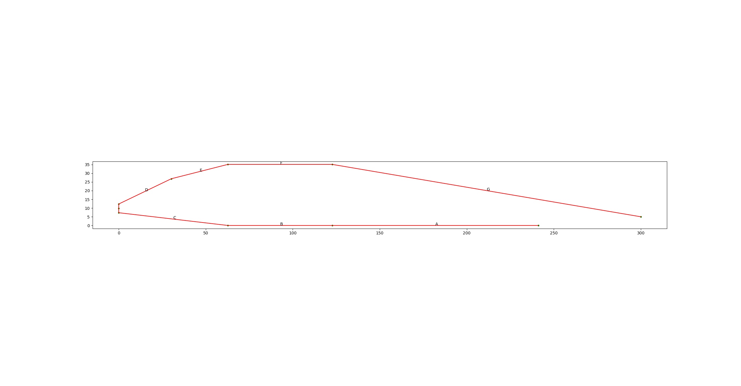
ft-wing.jpg

I could compute the lengths of the labeled edges (pad a little extra to make it around the leading edge radius) and would have enough to get out my ruler and start marking up a piece of foamboard. I could take it further and probably generate svg outlines given a wing span for the full cut file or at least a preview ...

Would this be stupid overkill? Is there something already far better? Is it just as easy to grab an existing wing design like FT recommends? Looking for thoughts/feedback if this would be useful or a waste of time? And I have plenty of other things to do so if it's a waste of time, be honest with me, I can take it!

Thanks!

Curt.

P.S. here's my quick hack python code.

Code:
#!/usr/bin/env python3

# this is a quick test to compute dimensions for a flight test style
# folded foam board wing ... loosely based on the clarky airfoil sorta
# kinda

import math
import matplotlib.pyplot as plt
import numpy as np

# units: let's do mm
r2d = 180 / math.pi

material_mm = 5                 # mm

# clarky numbers
max_thickness_perc = 0.117      # vertically proportional to chord
max_point_perc = .309           # longitudinally proportional to chord
le_raise_perc = .28             # vertically proportional to max height

# basic proportions
spar_perc = 0.20                # longitudinally proportional to chord
aileron_perc = 0.23             # desired overhang for ailerons

# edit this to size wing
chord_mm = 300
print("wing chord mm: %.0f" % chord_mm)

# compute things
max_mm = chord_mm * max_thickness_perc
print("max thickness mm: %.0f" % max_mm)

le_height_mm = max_mm * le_raise_perc

spar_width_mm = chord_mm * spar_perc
spar_height_mm = max_mm - 2*material_mm
print("spar width mm: %.0f" % spar_width_mm)
print("spar height mm: %.0f" % spar_height_mm)

max_point_mm = chord_mm * max_point_perc
half_spar = spar_width_mm * 0.5
spar_start_mm = max_point_mm - half_spar
spar_end_mm = max_point_mm + half_spar
print("spar start mm: %.0f" % spar_start_mm)
print("spar end mm: %.0f" % spar_end_mm)

le_crease_mm = spar_start_mm * 0.5
print("leading edge crease mm: %.0f" % le_crease_mm)

ail_overhang_mm = chord_mm * aileron_perc
print("desired aileron overhang mm: %.0f" % ail_overhang_mm)

# do trigs
aft_dist = chord_mm - spar_end_mm
print(aft_dist)
h = max_mm - material_mm
aft_hyp = math.sqrt( (h*h) + (aft_dist*aft_dist) )
print(aft_hyp)
angle = math.asin(h/aft_hyp)
print("angle deg:", angle*r2d)

mat2 = material_mm*2
act_overhang_mm = mat2 / math.tan(angle)
print("actual overhang: %.0f" % act_overhang_mm)

# inner points
nose = [material_mm, le_height_mm]
bot_front_spar = [spar_start_mm, material_mm]
bot_rear_spar = [spar_end_mm, material_mm]
top_front_spar = [spar_start_mm, max_mm-material_mm]
top_rear_spar = [spar_end_mm, max_mm-material_mm]
bot_te = [chord_mm-act_overhang_mm, material_mm]
final_te = [chord_mm, 0]
inner = np.array([bot_te,
                  bot_rear_spar,
                  bot_front_spar,
                  nose,
                  top_front_spar,
                  top_rear_spar,
                  final_te
                  ])

# compute outer points
nose_bot = [0, le_height_mm - material_mm*0.5]
nose_true = [0, le_height_mm]
nose_top = [0, le_height_mm + material_mm*0.5]
bot_front_spar = [spar_start_mm, 0]
bot_rear_spar = [spar_end_mm, 0]
top_front_spar = [spar_start_mm, max_mm]
top_rear_spar = [spar_end_mm, max_mm]
bot_te = [chord_mm-act_overhang_mm, 0]
final_te = [chord_mm, material_mm]
# dance
xdiff = spar_start_mm
ydiff = max_mm - nose_top[1]
len = math.sqrt(xdiff*xdiff + ydiff*ydiff)
base = [nose_top[0] + xdiff*0.5, nose_top[1] + ydiff*0.5]
xoff = -ydiff*0.05
yoff = xdiff*0.05
crease = [base[0]+xoff, base[1]+yoff]
outer = np.array([bot_te,
                  bot_rear_spar,
                  bot_front_spar,
                  nose_bot,
                  nose_true,
                  nose_top,
                  crease,
                  top_front_spar,
                  top_rear_spar,
                  final_te
                  ])


le_pad = (material_mm*2*math.pi)/4 - material_mm
print("leading edge radius pad: %.1f" % le_pad)

def my_annotate(ax, text, p1, p2):
    p = (np.array(p1) + np.array(p2))*0.5
    pt = p.copy()
    #if side == "top":
    #    pt[1] += material_mm
    #else:
    #    pt[1] -= material_mm
    ax.annotate(text, xy=p, xytext=pt)
    #arrowprops=dict(facecolor='black', shrink=0.05),
    #horizontalalignment='right', verticalalignment='top')
    
# plot
fig = plt.figure()
ax = fig.add_subplot()
x, y = outer.T
ax.scatter( x, y, marker=".", color="g" )
ax.plot( x, y, color="r" )
#x, y = inner.T
#ax.scatter( x, y, marker=".", color="g" )
#ax.plot( x, y, color="b")
my_annotate(ax, "A", outer[0], outer[1])
my_annotate(ax, "B", outer[1], outer[2])
my_annotate(ax, "C", outer[2], outer[3])
my_annotate(ax, "D", outer[5], outer[6])
my_annotate(ax, "E", outer[6], outer[7])
my_annotate(ax, "F", outer[7], outer[8])
my_annotate(ax, "G", outer[8], outer[9])
ax.set_aspect('equal')
plt.show()
 

clolsonus

Well-known member
Sounds like not too many people are laying out their wings from scratch, but I might still mess with this a bit more. Here is one more updated picture with dimensions labeled and the total height of the material needed (up to you to figure out how much wing span you want and what shape you want your wing tips.) The overhang/bottem-trailing-edge is computed so that the geometry works out with a strip of foam at the bottom trailing edge. I did a raised leading edge to match clarky, but that could get dropped, especially for smaller wings. The goal here is so I can layout my sheet on the floor, measure, mark, cut and then be able to fold it all together properly. Obviously all the FT designs have this worked out perfectly already, but if you wanted something different, it would be easy to mess up and not have it come out right and then go through a few iterations of trial and error ... hoping to minimize that.

So for example, i asked for a chord of 300mm (about 11 3/4"). Code figured out the segment lengths and added them up. So my sheet of foam would need to be at least 554m (21 3/4") so it might be too big for a standard foam sheet, unless I rotated it 90 degrees and got the 30" height ... and then used multiple sheets to add span.

I think I figured out that the biggest wing I could build with a single sheet of foam using the 30" direction for chord is about 400m (15 3/4") chord with 20" span per panel. Anway, thanks for letting me think out loud here. :)
ft-wing-300mm.jpg
 

JasonK

Participation Award Recipient
I happen to do some layouts like that myself but not at the detail level your doing, a few basic measurements to get a really basic wing fold. I have also just used the Tiny Trainer's wing template for some of my planes to get the score/cut lines worked out when I needed the same cord length - which worked really well.

A good working tool like this could be useful - at least in some cases, I would definitely be interested to see it. However, myself, if I went to far down this road, i would likely have myself looking at at hotwire setup with 2 x-y setups on each end, and then be hot-wiring out a wing. I think one of the draws to the FT style wing is that it is 'solved' and doesn't take much work to make use of it.
 
I don't think this will be helpful because most people aren't draftsmen using Autocad.

I think what you're doing is drawing a section and creating a tool to tell you the lengths unfolded. Cool.

If you get into hard-core drafting it becomes a simpler exercise. Basically I draw a wing section, or as many sections as I need if the chord changes along the wing. Then using geometry and basic drafting techniques I transfer the sections to the complete wing, unfolded.

Sorry this isn't helping you! Maybe it can help with a general understanding of how thing might be done.

zzzScreenshot 2021-03-06 135231.png zzzScreenshot 2021-03-06 135408.png
 

TEAJR66

Flite is good
Mentor
Looks a little complicated.
In Sketchup, I can draw a root chord profile of 10" (10" gives 1.17" thickness at 28.3" chord length) then scale to the desired chord length. Then extrude to desired span and move wingtip end for sweep and dihedral, and scale for taper. Then unfold and flatten. Now you have the diagram, dimensions for the lines and something you can share as a pdf. It goes pretty quick.

If it is a tool that you or others will use, it is worth developing. Anything that makes things easier, and integrates well with your techniques, is worthwhile.
 
Last edited:

clolsonus

Well-known member
I appreciate all the thoughtful comments. I see that people have found their way using their favorite tools and are quite effective, so that is all great. This is in no way suggesting anyone should change their approach, but I sadly think in python rather than through interactive sketch tools, so if this helps anyone with similarly screwed up brain get a perfectly folded wing on their first try, then great.

Here is one more quick update. I now compute spar dimensions and have dropped one non-essential point on the outer wing perimeter. The script gives segment dimensions and cumulative dimensions (which are easier to measure out if you are building on your basement floor.) Here is a sample screenshot of a 250mm chord wing:
ft-wing-250.jpg


Program output looks like this:
Code:
$ ./ft-wing.py 250
wing chord mm: 250
max thickness mm: 29
spar width mm: 50
spar height mm: 19
spar start mm: 52
spar end mm: 102
leading edge crease mm: 26
desired aileron overhang mm: 58
actual overhang: 58
leading edge radius pad: 2.9
Wing segments unfolded:
A: 140 Cumulative: 140 mm
B: 55 Cumulative: 195 mm
C: 31 Cumulative: 226 mm
D: 28 Cumulative: 254 mm
E: 50 Cumulative: 304 mm
F: 150 Cumulative: 454 mm
Total (mm): 454

Spar:
width: 50 mm
height: 19 mm
Total(mm): 88

Trailing edge spacer:
width: 12 mm

The code has been placed in my git model airplane designer repository here (open-source). There is more stuff in the repository, but this script should be standalone.

https://github.com/clolsonus/madesigner/blob/master/sandbox/ft-wing.py

The idea is this gives you the unfolded dimensions of the wing and the places to make your cuts/creases. It's up to you to decide what wing span and wing tip shape you want.
 

Ketchup

4s mini mustang
Usually I would just design a wing with an idea of what I want in my head, a piece of paper and a calculator. Some Pythagorean theorem gets me all the measurements I need. This does seem pretty easy though. I will probably keep doing what I do currently but this seems like it would be really helpful especially for more complex airfoils.
 

JasonK

Participation Award Recipient
Do you have this setup in a way that would let you change the cord to thickness ratio/material thickness or does one need to edit code to make those changes?
 

clolsonus

Well-known member
I included a command line option to set material thickness (defaults to 5mm). The airfoil thickness is hard coded to mimic clarky, but it's just a single number (ratio of chord to thickness) so it's one quick change to the code to change. That could be a command line option too potentially. If you can get to the point of running a python script on your system, then editing it to change some of these parameters is like 2 seconds. You can also set where in the chord you want the thickest point and probably a few other things if you needed to nudge the design around to fit your material and your design constraints.
 

JasonK

Participation Award Recipient
I included a command line option to set material thickness (defaults to 5mm). The airfoil thickness is hard coded to mimic clarky, but it's just a single number (ratio of chord to thickness) so it's one quick change to the code to change. That could be a command line option too potentially. If you can get to the point of running a python script on your system, then editing it to change some of these parameters is like 2 seconds. You can also set where in the chord you want the thickest point and probably a few other things if you needed to nudge the design around to fit your material and your design constraints.
yup, found it, ran it, got what I needed. for what I am making I need the spar to be a bit thicker then what the math did, so I reverted the math and figured it out.

Getting python working was easy... was the language I used for advent of code 2020 ;)
 

clolsonus

Well-known member
For me, this is just a random idea that may or may not happen, but I want to make a version of the Lazy-B, but instead it will be the Lazy-V ... sorta a big fat FT sparrow. I want to make the biggest chord I can with the 30" direction of a piece of foam board, and then probably go 3 sheets wide (so 60" total wing span) and then a big fat V tail -- no ailerons, just v tail rudder/elevator mixed like the sparrow.

Jason, if you beat me to building anything based on this code, please post a picture here. I made a little test section (2" wide) to test that the math and dimensions and folds all worked and it seemed to come out just as expected, so fingers crossed.
 

JasonK

Participation Award Recipient
I have been working on a vtol and if I need to rebuild the wing I will probable use this as I have an idea on how to bring the weight down some, but I don't want to rebuild the whole thing at the moment.
 

clolsonus

Well-known member
Ok, here's my dumb picture ... I didn't warm up the glue gun, just holding the pieces together approximately. Just a 2" wide test:
(and for the nitpicky, I think I cut a 225mm chord airfoil, and then subsequently was playing around with numbers so I'm showing a 400mm chord on screen ... so they aren't the same size, but the same shape/proportions.)

IMG_20210309_185339347_HDR.jpg
 

clolsonus

Well-known member
I have a question. Is there a design reason (or structural reason) to place the U channel spar right side up vs. upside down? I think the storch design has it opposite of what I've show above, but the other FT designs I've built have had smaller/simpler wings. Thanks in advance for any thoughts or insight!

I'm on my 2nd try at building a full wing panel tonight (my first try I got my A fold vs. B fold mixed up and made the spar too narrow and tall and didn't notice until I had the whole wing glued together and things weren't lining up quite right. Dohhh! Good thing it's only foam. The dollar tree person was kind enough to find a full box of white foam in the back room last time I visited so I have some breathing room to make mistakes now.
 

Pieliker96

Elite member
I have a question. Is there a design reason (or structural reason) to place the U channel spar right side up vs. upside down? I think the storch design has it opposite of what I've show above, but the other FT designs I've built have had smaller/simpler wings. Thanks in advance for any thoughts or insight!

I'm on my 2nd try at building a full wing panel tonight (my first try I got my A fold vs. B fold mixed up and made the spar too narrow and tall and didn't notice until I had the whole wing glued together and things weren't lining up quite right. Dohhh! Good thing it's only foam. The dollar tree person was kind enough to find a full box of white foam in the back room last time I visited so I have some breathing room to make mistakes now.
If I had to guess it's that foam is stronger in tension than compression, where it tends to buckle. In upright flight, the top of the wing is loaded in compression, so it makes sense to double up the foam where it's weaker.
 

clolsonus

Well-known member
Sorry to keep spamming on this topic, but I couldn't resist. Back story, I tried to create a tapered wing section and failed miserably. Then I tried to trim manually so it would be correct, and failed even worse. So I sat down and refactored my existing code, and wrote some more code. So you input a root chord, a tip chord, a 1/2 span, and a sweep (which is a leading edge offset at the tip, not an angle right now.) The code computes the two profiles (root and tip) then generates and unfolds the surfaces. There was some tricky thinking there that I originally couldn't wrap my head around (so to speak) :)

So here is my first paper print out and test fold which seems right on as far as I can tell (but hard to take a good picture of it because it's flimsy paper):

IMG_20210316_172710555(1).jpg


And then here is the unfolded plot I created (you have to use your imagination to join the edges, it's just the fold lines and first and last edges that are shown):

test.png

The harder thing now might be to figure out how to get this from x, y coordinates that I can plot on a graph, to actual true scale outlines I can print or plot or something ... all of this if fun, but not too useful if I can't get it to the foamboard accurately at the correct much larger size.
 
Last edited:

Walden

Member
Fascinating thread. Somehow I just assumed most of us redesigned a new wing every time we scratch built a new plane. (Or perhaps it is just me who is that crazy? :unsure:) This is how I like to do it: first I'll simply draw CAD sketches for the side, front, and top views. Then breaking up each facet/fold into one or two triangles I simply use the Pythagorean theorem to find the sides of the triangles based on the X, Y, and Z dimensions from the profiles, create a CAD sketch for each part, and then sketch the design directly onto the foam board.
 

Attachments

  • 2.1prt_Wing.jpg
    2.1prt_Wing.jpg
    186.7 KB · Views: 0
  • 2.0-2.1top.jpg
    2.0-2.1top.jpg
    118.4 KB · Views: 0
  • Screenshot (1).png
    Screenshot (1).png
    480.5 KB · Views: 0
  • Screenshot (2).png
    Screenshot (2).png
    421.3 KB · Views: 0

clolsonus

Well-known member
Fascinating thread. Somehow I just assumed most of us redesigned a new wing every time we scratch built a new plane. (Or perhaps it is just me who is that crazy? :unsure:) This is how I like to do it: first I'll simply draw CAD sketches for the side, front, and top views. Then breaking up each facet/fold into one or two triangles I simply use the Pythagorean theorem to find the sides of the triangles based on the X, Y, and Z dimensions from the profiles, create a CAD sketch for each part, and then sketch the design directly onto the foam board.

And that's essentially the same process I'm using ... I compute the root and tip profiles (airfoil cross section) Then with span and sweep I can compute the triangles in between as you wrap around and I use a slightly different math approach, but then it's just stacking the triangles up against each other on a flat surface. My system couldn't do anything as origami creative as your design there!