Crawford Bros. Aeroplanes

Legendary member
I learned recently from @FoamyDM about a NASA test project called PRANDTL-D. He built his own version of the prototype and posted plans here: https://forum.flitetest.com/index.php?threads/prandtl-d-foam-board-wing-by-foamydm.58170/
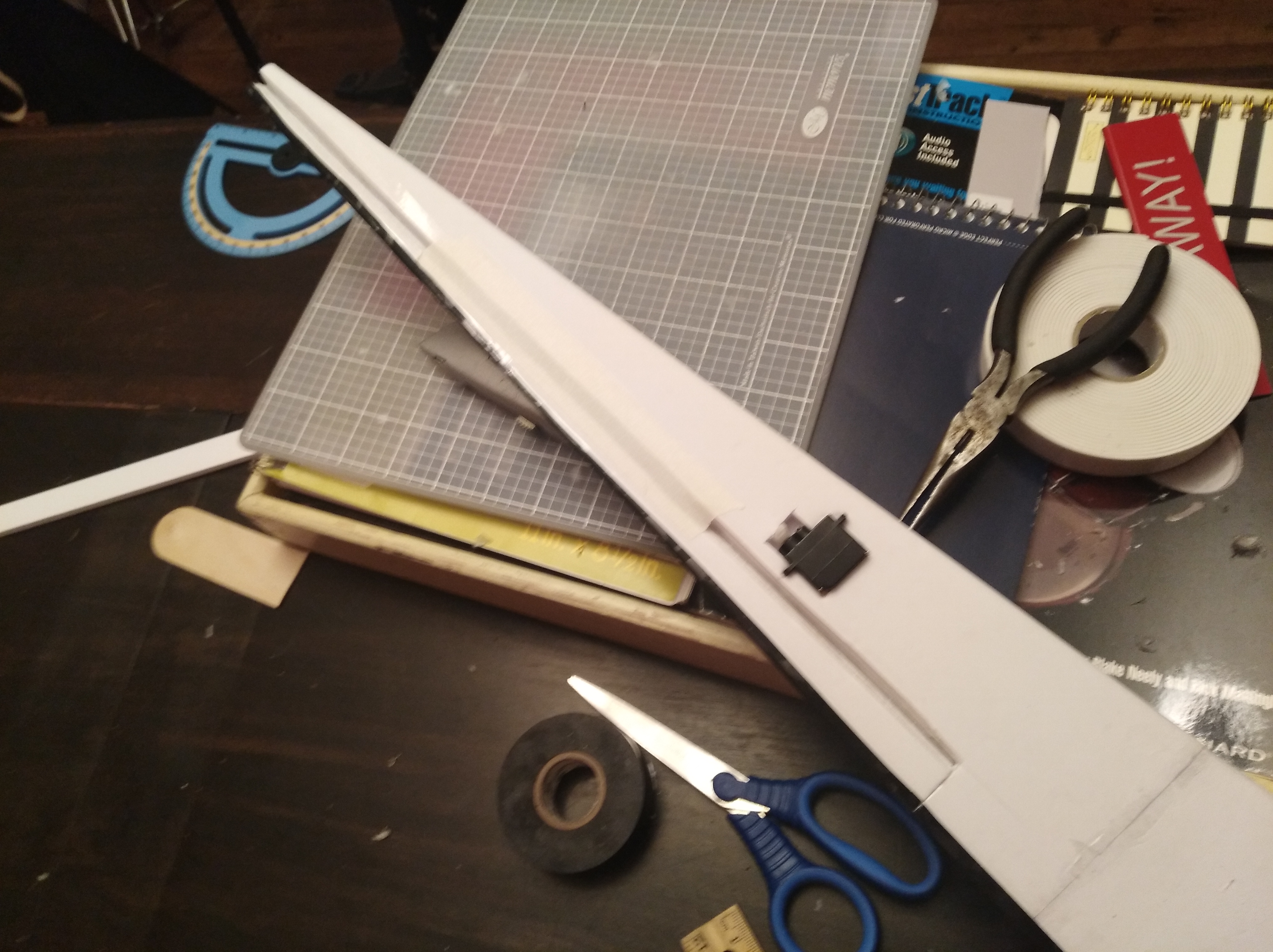
This morning I began building my own wing from @FoamyDM 's plans. I have both wings finished and will probably finish the airframe tomorrow. I plan on powering mine and using elevons, we'll see if I can make a system that fits and isn't too heavy.
IMG_20200110_203359.jpg

IMG_20200110_203407-1.jpg

The Prandtl wing concept is designed to produce proverse yaw, this makes true taillesss aircraft possible without the need for split flaps or vertical stabilizers. To induce proverse yaw the wingtip is twisted forward, this generates thrust during banks and rolls and yaws the plane into a roll while keeping the plane stable in level flight. This is achieved through non-uniform twist throughout the wing.
IMG_20200110_165928.jpg

On a Prandtl wing, the wingtip it twisted forward at a much shallower angle of attack than the rest of the wing. This coupled with dihedral generates induced thrust, resulting in proverse yaw. This is a simplified explanation, NASA's experiment report goes into further detail:
http://www.amaflightschool.org/sites/default/files/219072.pdf
PRANDTL-D glider project:
https://www.nasa.gov/centers/armstrong/news/FactSheets/FS-106-AFRC.html

I was out of Dollar Tree Foam Board when I began this project, but my brother had some Ross foam board that I decided to try. It has notable pros and cons over DTFB, for one it's more of a packing foam and less of a styrofoam. his means it's more flexible without removing the paper, and it tends to crumple rather than rip like DTFB. However, the paper backing can be peeled off DTFB to make it flexible. This is impossible with RFB, so shallow curves are stronger with the paper intact but moulding complex shapes is impossible. Because of this my Prandtl wing is incredibly rigid. In the future I may try using both RFB and DTFB for different parts of the same build, based on the strengths of each type of board.
 

Attachments

  • bellspanload.png
    bellspanload.png
    38.8 KB · Views: 0
  • linearload.png
    linearload.png
    31.3 KB · Views: 0
Last edited:

varg

Build cheap, crash cheap
Very cool. I can't help but wonder if it will have adequate yaw stability though without some sort of fairing/body that has vertical surface area or drag devices/winglets at the wing tips. I'm not the guy you're asking, but I'd go with a 110X class quad motor in tractor configuration for powering something like that. Light weight, weight where you want it, and easily capable of 1:1 thrust to weight ratio assuming AUW is less than 400g or so.
 

Crawford Bros. Aeroplanes

Legendary member
A small quad motor is definitely the way to go, I'm not sure what battery to use though. My smallest is a 1300 mAh 3s, that'll never fit.
I did some quick test fitting and I think I've found a system that'll work. I'll build a sort of "electronics tray" between the wings to house the electronics open-top style so I'll have plenty of room.
I'll power it with an Emax 2207 2400 kv turning a 6" low pitch prop, run off a 1300 mah 3s. I've used this setup before, it should be docile enough to make this fly more like a powered glider on lower throttle. Calculated AUW with this setup is 328g with wing loading of 1.32g/sq. in.
I want to try this in a pusher configuration, however where I end up putting the motor all depends on how the cg ends up. I'll test fit and weigh everything before finalizing the motor location.
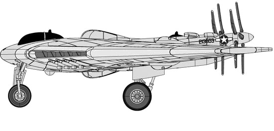
As a pusher a slight upward thrust angle will be important, @FoamyDM I think this is why you had trouble with yours. If I remember correctly flying wings with a narrow chord usually require a bit of downthrust to keep pitch under control. Jack Northrop has some research somewhere that confirms this, but it's almost 11:00 pm right now so I'll dig it up later. Case in point check out the prop angle on Northrop's N9M:
N9M-3view.jpg

And even the massive, 172 ft XB-35:
northrop-xb-35.jpg

Even the jet-powered YB-49 had slight downthrust, although it doesn't show up very well in a 3-view. On wings like this with a narrow chord any upthrust at all is usually a no-go.

@varg Usually wings do require split flaps or v-stabs to remain stable, but the point of this project is to build a wing that remains stable using a phenomenon called proverse yaw. It's explained in the report and the NASA site I linked to but here's how it works in a nutshell: the wingtips are twisted forward about 9 degrees. When the plane sideslips, i.e. in a bank or uncontrolled yaw, the twisted wingtip on the trailing side of the sideslip actually generates thrust and yaws the airplane. If it doesn't work I'll just add winglets and fly it as a normal wing, but I'm not the first person to do this so I shouldn't have any problems.
 
Last edited:

Crawford Bros. Aeroplanes

Legendary member
I did some glide testing today. My first toss had the plane too tail heavy, it nosed up, looped, and came straight down. However, it remained perfectly straight while doing so and landed directly in front of where I threw it. I found that about 50g of coins in the nose got the CG where I wanted, just ahead of the trailing edge at the very middle of the wing. The airframe weighs 116g unloaded, which means AUW for glide testing was 166g with wing loading at 0.66g/sq. in. I didn't have plenty of room for extended glides (only about 30 ft in my neighbor's yard with solid objects on all sides), but the next flights revealed that the plane was extremely stable at low speed. I tried to toss the plane slightly rolled to the left to test proverse yaw, but it returned to center and flew straight anyway. I may have had too much dihedral. After about 4 or 5 flights it was too dark to continue so I called it a day.
I may try more glide testing at the park tomorrow to really see if I'm getting proverse yaw. Electronics are on their way so I should have a powered model shortly.
 

Crawford Bros. Aeroplanes

Legendary member
Test fitted the battery and receiver to get an idea of how to get the cg where I want it. I used quarters as placeholders for the motor and prop as I don't have those yet. In a tractor configuration the cg is far too nose heavy, but as a pusher it's right where I want it. Because of the intense sweep of the wings there's a lot of mass behind the center section, but the battery balances this nicely on its own. As a pusher the motor is almost directly on the cg.
 

Crawford Bros. Aeroplanes

Legendary member
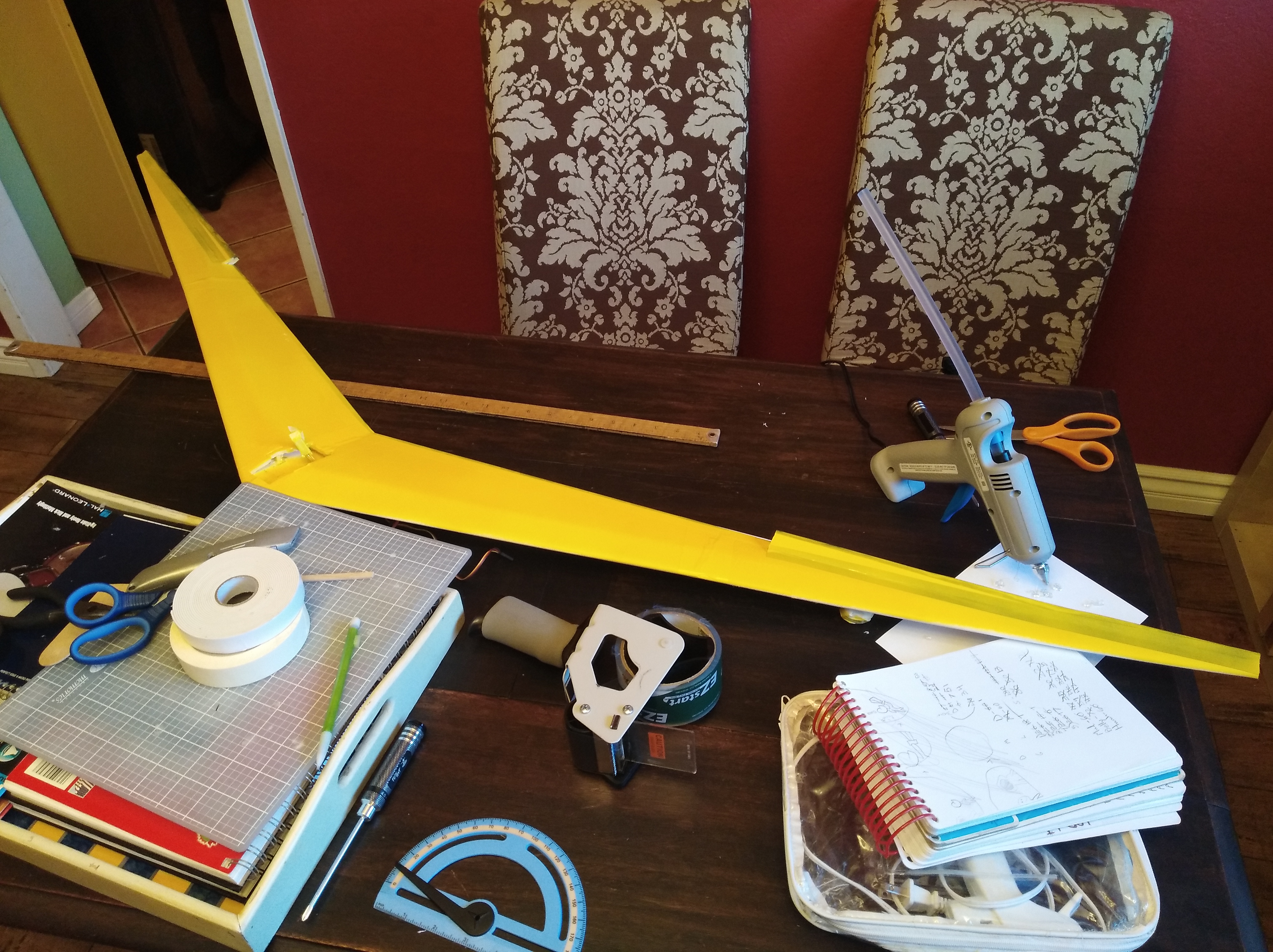
Started painting today. It's a bit chilly and getting dark so I still have a few more coats to do on the top. It'll be yellow on top and blue on the bottom, like the Northrop wings.

IMG_20200113_153608.jpg


It looks so much better in the photo but I have a ways to go to cover that electrical tape.
 
Last edited:

Piotrsko

Master member
Ok read the papers, which made a headache (typical). Question: your planform looks like a typical V instead of a W. I am guessing when they specify the forward sweep they are actually discussing a term that I consider to be washout. Looking at the leading edge, it looks like thus: ---------/ but only it is -9 degrees more or less where washout is -1 or -2. Could you clarify.

traditionally, flying wings have not needed vertical stabs if one accepts adverse yaw as a feature of design and plans surface throw accordingly. Even more so if this works as designed. I believe the YB-49 had some, but I suspect that was to counter the torque of the turbojets. Due to the contra rotation on the radials, it wasn't needed on the YB-35. Suspect you'll need some left thrust on your pusher in addition to the copius up thrust.
 
Last edited:

Crawford Bros. Aeroplanes

Legendary member
Ok read the papers, which made a headache (typical). Question: your planform looks like a typical V instead of a W. I am guessing when they specify the forward sweep they are actually discussing a term that I consider to be washout. Looking at the leading edge, it looks like thus: ---------/ but only it is -9 degrees more or less where washout is -1 or -2. Could you clarify.

traditionally, flying wings have not needed vertical stabs if one accepts adverse yaw as a feature of design and plans surface throw accordingly. Even more so if this works as designed. I believe the YB-49 had some, but I suspect that was to counter the torque of the turbojets. Due to the contra rotation on the radials, it wasn't needed on the YB-35. Suspect you'll need some left thrust on your pusher in addition to the copius down.
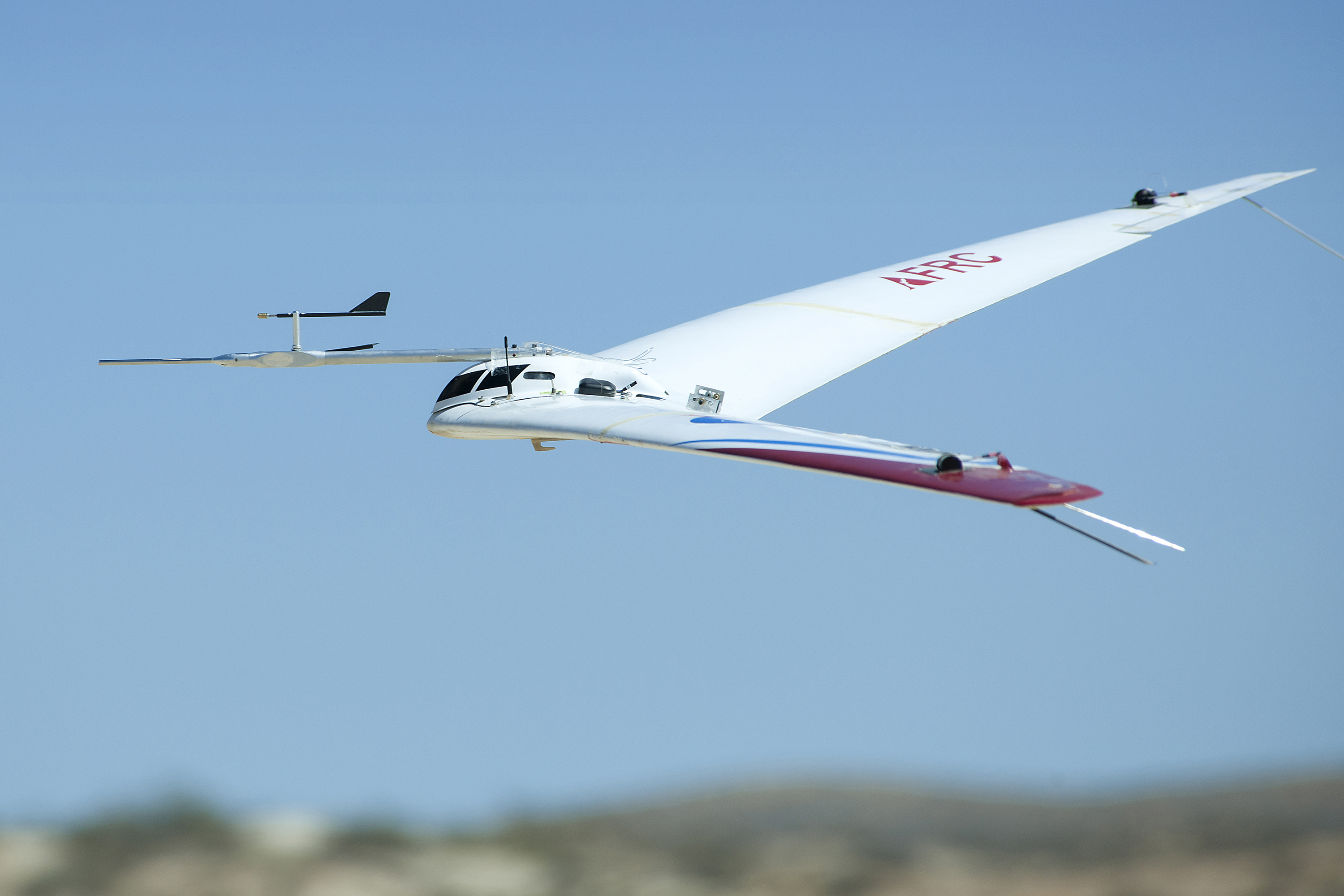
The "forward sweep" being discussed is washout. The term I prefer to use is "forward twist" to differentiate from a forward swept wing such as the X-29. When washout is typically applied the wing root is twisted back at an increased angle of incidence to ensure gentle stall characteristics, while on a Prandtl wing the wingtip is twisted forward at a negative angle of incidence to encourage proverse yaw.
This photo of NASA's wing shows the twisted wing pretty well:
prantwingnasa.jpg


As for adverse yaw and flying wings both the YB-35 and YB-49 had problems with "hunting," (uncontrolled yaw) which made accurate unguided bombing difficult. Northrop used "split ailerons" to act in place of a v-stab to control yaw, but this didn't fix the problem fully. The YB-49 was eventually fitted with a series of small v-stabs but this only lessened the issue. The B-2 probably has this issue too, but Northrop has likely juts worked around it with guidance computers and what-have-you. Plus, guided munitions make a difference.

Here's a link to FoamyDM's PRANDTL-D, he posted more of the science than I did. I left a lot of it out because I started my build there and sort of just picked it up and moved it here to avoid hijacking his thread.
https://forum.flitetest.com/index.php?threads/prandtl-d-foam-board-wing-by-foamydm.58170/
 

FoamyDM

Building Fool-Flying Noob
Moderator
This wing has a number of things happening about the same time. First is the airfoil shape starts at the root as a typical Horten wing shape. Like a Clark ay with the trailing edge curved up 5-6°. When the Angle of Incidence is 8, that returns the separated air near normal to surround airflow. At ~75% this airfoil transitions to a more symmetrical shape.
In addition, the Angle of Incidence varies across the length of the wing too. For 8° to more by mid wing then to -2° by the tips.
Lastly is the dihedral of the craft. Which helps with hands-off stability. It's almost as if the motor is causing a type of kiting here, just very effective and controlled.

The real trick is, to do all those things reliably without having cross sections. Thanks to @Crawford Bros. Aeroplanes, he has shown that we've found at least one way to reliably reproduce this effect. And proven that my written nonsense, isn't nonsense at all. Thank you.
The hard part with this is the control surfaces are SO thin, I wonder how effective they are
 

Crawford Bros. Aeroplanes

Legendary member
This wing has a number of things happening about the same time. First is the airfoil shape starts at the root as a typical Horten wing shape. Like a Clark ay with the trailing edge curved up 5-6°. When the Angle of Incidence is 8, that returns the separated air near normal to surround airflow. At ~75% this airfoil transitions to a more symmetrical shape.
In addition, the Angle of Incidence varies across the length of the wing too. For 8° to more by mid wing then to -2° by the tips.
Lastly is the dihedral of the craft. Which helps with hands-off stability. It's almost as if the motor is causing a type of kiting here, just very effective and controlled.

The real trick is, to do all those things reliably without having cross sections. Thanks to @Crawford Bros. Aeroplanes, he has shown that we've found at least one way to reliably reproduce this effect. And proven that my written nonsense, isn't nonsense at all. Thank you.
The hard part with this is the control surfaces are SO thin, I wonder how effective they are
That's why I made the ailerons so long. Well said with the powered kiting, that's exactly what I'm going for.
 

varg

Build cheap, crash cheap
Any updates? I was wondering how this would turn out with a lower Reynolds number in a small, slow foam model. Just couldn't see it working as well scaled down so much but am hoping I guessed wrong